

ppl_05_e2
.pdfID: 3658
Customer: Oleg Ostapenko E-mail: ostapenko2002@yahoo.com Customer: Oleg Ostapenko E-mail: ostapenko2002@yahoo.com
And, from the Principle of Continuity, as rate of mass fow entering the stream tube equals the rate of mass fow leaving the stream tube:
ρ1 A1 v1 = ρ2 A2 v2
And, since ρ is a constant for an incompressible fuid,
A1 v1 = A2 v2
And so, the Principle of Continuity teaches us that the product Av must have the same value at any point in the stream tube. We can, therefore, deduce that:
CHAPTER 3: LIFT
The Principle
of Continuity teaches
that the
rate of mass flow of an incompressible fluid through a stream tube is constant.
Av = constant for any region of fow of an ideal fuid
This equation is known as the Continuity Equation.
The Continuity Equation derived from the Principle of Continuity tells us that, in any region of fuid fow, the cross-sectional area, A, of the stream tube multiplied by the velocity, v, of the fuid always gives us the same constant value, and when A increases, v must decrease, and vice versa.
The Continuity Equation also enables us to interpret the streamline picture. If the cross-sectional area of a stream tube decreases, the distance between individual streamlines which make up the stream tube decreases, too, so the streamlines are closer together. But as velocity, v, multiplied by cross-sectional area, A, is a constant, as A decreases v must increase. Therefore, we see that widely spaced streamlines within any region of fuid fow indicate a lower fow velocity than the velocity of the fuid in a region of fow where the streamlines are close together.
So, in summary, for the steady fow of an ideal fuid:
increase in cross-sectional area |
= |
decrease in velocity of |
of stream tube |
|
fuid fow |
decrease in cross-sectional area |
= |
increase in velocity of |
of stream tube |
|
fuid fow |
tightly packed streamlines = higher velocity widely spaced streamlines = lower velocity
The Principle
of Continuity teaches that in
a streamtube
of decreasing cross-sectional area, the speed of an incompressible airflow will increase.
Looking back at Figure 3.13, we can see that because A2 is larger than A1, the velocity v2 must be less than v1; and, so, the fuid particles in the stream tube must have been decelerated in moving from A1 to A2. Newton’s 2nd Law tells us that for this to happen, a resultant force must have been applied in the direction from A2 towards A1. Now, if the fow is horizontal, gravitational force is constant over the whole length of fow. But, the deceleration can have been caused by a greater internal pressure (Force/Area) acting at A2 than at A1. We can conclude, therefore, that in the steady, horizontal fow of an ideal (incompressible) fuid, the internal pressure of the fuid is greatest where the speed of the airfow is lowest, and vice versa. (This, of course, is the same statement as that made by Bernoulli’s Principle and provides a clue as to the close relationship between the Bernoulli and the Newtonian theories of lift.)
47
Order: 6026
Customer: Oleg Ostapenko E-mail: ostapenko2002@yahoo.com CHAPTER 3: LIFT Customer: Oleg Ostapenko E-mail: ostapenko2002@yahoo.com
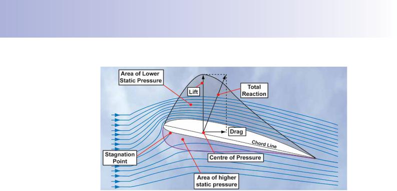
Figure 3.14 Airflow around an aerofoil at a small angle of attack – streamlines and variations in static pressure within the airflow.
Let us now consider the case of steady low-speed airfow around an aerofoil, knowing that, in these conditions, air can be assumed to be an ideal fuid. The study of airfow around aerofoils is often conducted in a wind tunnel, and if jets of smoke are introduced into the airfow, they will form visible streamlines which make it actually possible to see the airfow around the aerofoil.
If we observe such a situation where an aerofoil is angled to the relative airfow at a small positive angle of attack, we can observe that the streamlines made visible by the smoke are closer together in the air fowing over the aerofoil than those in the airfow passing underneath the aerofoil. This situation is depicted in Figure 3.14, above.
Just under the leading edge of the aerofoil, the airfow is brought to rest; this is called the stagnation point. There is a second, less important, stagnation point at the trailing edge.
We can, thus, now see for ourselves, from the streamlines, the correctness of the prediction that the turning effect of the wing on the air fowing around an aerofoil causes a change in the local speed of the airfow such that the speed over the upper surface of a wing is higher than the speed of the air fowing underneath the wing. As we have just learnt, where the speed (or velocity) of fow is lowest, the pressure of the airfow is highest and where airfow speed is highest the pressure is lowest.
Therefore, there exists a pressure differential across the wing, which generates a net force (pressure differential × wing area) acting in an upwards direction.
The explanation just given is a simple expression of how Bernoulli’s Principle of pressure variation with velocity change accounts for lift force.
Let us now look at how Bernoulli’s Principle is expressed through Bernoulli’s
Equation.
BERNOULLI’S PRINCIPLE.
Bernoulli’s Principle concerning the relationship between pressure variations and the velocity changes in a fuid fow expresses a fundamental relationship of fuid
48

ID: 3658
Customer: Oleg Ostapenko E-mail: ostapenko2002@yahoo.com Customer: Oleg Ostapenko E-mail: ostapenko2002@yahoo.com
CHAPTER 3: LIFT
mechanics, and is derived from Newton’s Laws. This close connection between Bernoulli’s Principle and Newton’s Laws reveals, perhaps, that the two interpretations of lift that we have been considering – pressure differential across the wing, on the one hand, and rate of change of momentum of the air fow, on the other – boil down, ultimately, to one and the same thing: a unitary theory of lift. That depth of analysis goes beyond the scope of this book, but it is ftting that, as pilots, you be aware of the current scientifc discussions on the important subject of lift.
As we have mentioned, the generation of lift by an aircraft wing involves three fundamental principles of Physics: the Conservation of Momentum, the Conservation of Mass, and the Conservation of Energy. You have learnt that the explanation of lift using Bernoulli’s Principle concentrates on the issue of the Conservation of Energy, but, inevitably, the other two principles are involved, too.
We have already seen from the Continuity Equation – expressing Conservation of
Mass - that the rate of mass fow of an ideal fuid is constant at all points along a stream tube. The Continuity Equation has also taught us that, within any region of fow, where the streamlines are widely spaced, a lower velocity of fow is indicated, and where the streamlines are close together a higher fow-velocity is indicated. We have also deduced from the Continuity Equation that the pressure of the fuid is greatest where the speed of fow is lowest, and vice versa.
Bernoulli’s Principle states that the total energy within an ideal fuid fow is constant. You have also learnt that for a horizontal fow of ideal fuid, such as the fow of low speed air around a wing, the total energy in the airfow consists of the kinetic energy of airfow, that is the energy it possesses by virtue of its mass and its velocity, plus the airfow’s pressure energy, that is, the energy due to the pressure of the air acting in all directions within the fow.
Dynamic and Static Pressure in an Airflow.
If moving air is brought to rest, its kinetic energy does work on the object which brings it to rest. In being brought to rest, the air applies a force on the object - which of course will have a certain frontal area - and, therefore, the air will exert a pressure on that object due solely to the initial velocity of the air. The name that aerodynamicists give to this kind of pressure is dynamic pressure. Figure 3.15 overleaf, illustrates how the dynamic pressure of an airfow may be approximately registered by a fat plate attached to a wall by a spring. We will assume that atmospheric static pressure acts on every square inch of the plate, on both the front and back surfaces. So, the value of pressure sensed by the spring will be the value of the dynamic pressure, and the compression of the spring is due to the dynamic pressure alone. (As we have mentioned, this method registers dynamic pressure only approximately. However, the present reasoning is accurate enough to give you an initial idea of the nature of dynamic pressure.)
You can feel dynamic pressure for yourself, if you hold your hand out of the window of a moving car, with your palm perpendicular to the air fow (see Figure 3.16, overleaf).
To contrast dynamic pressure with what Bernoulli’s Principle calls, simply, the pressure energy in an airfow - that is, the pressure in the airfow which acts in all directions -
The total
energy within an ideal
fluid flow is
constant. For a horizontal flow, total energy consists of kinetic energy and pressure energy.
The pressure
that moving air exerts on an
object, by virtue
of the air’s velocity, is called dynamic pressure.
49

Order: 6026
Customer: Oleg Ostapenko E-mail: ostapenko2002@yahoo.com CHAPTER 3: LIFT Customer: Oleg Ostapenko E-mail: ostapenko2002@yahoo.com
The total pressure in an
ideal airflow is equal to
dynamic pressure plus static pressure, and is a constant.
Figure 3.15 Dynamic pressure: Airflow striking a plate.
Figure 3.16 You can feel dynamic pressure for yourself.
pressure energy is referred to in most text books for pilots as static pressure. So, if we think of all the energy in a moving mass of air as being pressure, we can re-state
Bernoulli’s Principle for airfow as follows:
Total Pressure = Dynamic Pressure + Static Pressure = Constant
In a horizontal ideal airflow
around a wing, when
dynamic pressure increases, static pressure decreases, and vice versa.
Figure 3.17 Measuring static pressure around a wing.
50

ID: 3658
Customer: Oleg Ostapenko E-mail: ostapenko2002@yahoo.com Customer: Oleg Ostapenko E-mail: ostapenko2002@yahoo.com
N.B. When we are considering Bernoulli’s Principle applied to airfow around the wings and/or fuselage of an aircraft in fight, do not confuse static pressure with the ambient atmospheric pressure. In Bernoulli’s Principle, static pressure refers to the pressure exerted in all directions within the air fow, itself, not the ambient atmospheric pressure measured by a stationary observer.
The variation in static pressure in the airfow around a wing has traditionally been measured in wind tunnels by using an aerofoil with small holes drilled into the upper and lower surfaces and connecting these holes to manometer tubes containing a suitable liquid. The different heights of the liquid within the tubes shows the distribution of static pressure around the aerofoil. (See Figure 3.17, previous page.)
So we may now, in the light of what we have learned so far, reword Bernoulli’s
Principle applied to the airfow which meets an aerofoil at a small positive angle of attack, at speeds below half the local speed of sound, as follows:
CHAPTER 3: LIFT
Static pressure is exerted in all directions.
Total pressure in the airfow around an aerofoil is constant. Over the upper surface of the wing, where there is an increase in velocity, the dynamic pressure increases and the static pressure falls. Below the wing where there is a decrease in the velocity of the airfow, the static pressure increases and the dynamic pressure falls.
The static pressure is highest of all at the stagnation point, just under the leading edge of the aerofoil.
From Bernoulli’s Principle, then, we can conclude that the pressure differential which exists across the aerofoil can account for the lift force which acts upwards from the area of higher pressure to the area of lower pressure.
Over the upper
surface of a wing, the
velocity of the
airflow increases and static pressure falls. Under the wing, velocity decreases and static pressure rises.
Bernoulli’s Equation.
Let us now look at the equation which expresses Bernoulli’s Principle mathematically. The derivation of Bernoulli’s Equation is beyond the scope of a book of this nature.
Here we will just state Bernoulli’s Equation for air of density ρ, fowing horizontally over an aircraft fying at a velocity, v, well below 300 knots, so that we can make all the assumptions we have mentioned in the chapter about the air being treated as an ideal fuid. Expressed as an equation, then, for this particular case, Bernoulli’s
Principle may be written:
p + ½ ρv² = constant
This is Bernoulli’s Equation, where ½ ρv² represents the dynamic pressure of the air fow, sometimes referred to by the symbol Q, and p represents the static pressure in the airfow.
The total pressure of the airfow, p + ½ρv² is a constant, so that any increase in velocity will result in an increase in dynamic pressure and a reduction in static pressure.
The pressure
differential acting across
the aerofoil acts
in an upwards direction and can account for the lift force developed by a wing.
Any increase in
the speed of an incompressible
airflow will
result in an increase in dynamic pressure and a reduction in static pressure.
51

Order: 6026
Customer: Oleg Ostapenko E-mail: ostapenko2002@yahoo.com CHAPTER 3: LIFT Customer: Oleg Ostapenko E-mail: ostapenko2002@yahoo.com
Figure 3.18 Streamlines in an airflow meeting a wing.
Lift can be accounted
for by the difference
in static pressure above and below the wing.
How Bernoulli’s Equation Predicts the Lift Force Generated by a Wing.
Let us now review all of what we have learnt about how Bernoulli’s Principle explains the lift force on a wing.
Figure 3.18, represents a wing of aerofoil cross section in a wind tunnel where smoke has been introduced into make the streamlines visible to us. There is a small positive angle of attack between the wing and the relative airfow. The exact value of this angle of attack need not concern us for the moment, but, it will lie between +2° and +8°. The angle in the diagram is not drawn to scale.
The streamlines show an upwash in the airfow just upstream of the wing and a downwash downstream of the wing. This turning effect of the wing on the airfow causes a rate of change of momentum in the air mass which, in turn, is the cause of the variations in the velocity of the airfow around the wing. The streamlines are relatively close together, just above the upper surface of the wing and relatively far apart below the wing’s under surface.
As we have learnt from our study of the Continuity Equation, widely spaced streamlines within any region of airfow indicate a lower air velocity than the air velocity in a region of fow where the streamlines are close together, and vice versa. We can see, therefore, from our observation of the streamlines that the speed of the airfow over the upper surface of the wing is higher than the free stream airfow in front of the wing and that the speed of the airfow beneath the wing is lower than the free stream airfow.
Bernoulli’s Equation, p + ½ ρv² = constant, teaches us that while the total pressure energy within an airfow is constant, where there are variations in the velocity of the airfow, there will be corresponding variations in static and dynamic pressure. Where the speed of the airfow is highest, dynamic pressure will be highest and static pressure will be lowest. Conversely, where the speed of the airfow is lowest, dynamic pressure will be lowest and static pressure will be highest.
As it is static pressure which acts in all directions (whereas dynamic pressure acts only in the direction of fow), it is the difference in static pressure above and below the wing which causes the pressure differential across the wing and the corresponding
52

ID: 3658
Customer: Oleg Ostapenko E-mail: ostapenko2002@yahoo.com Customer: Oleg Ostapenko E-mail: ostapenko2002@yahoo.com
CHAPTER 3: LIFT
lift force. The pattern of pressure distribution over the wing that we are considering is depicted in Figure 3.19. The aerodynamic force acts from the higher relative static pressure beneath the wing upwards in the direction of the lower static pressure above the wing. This force can be measured in a wind tunnel and is predicted by Bernoulli’s Equation.
The streamlines show us that the speed of the airfow is highest over the forward section of the wing and lowest under the forward section of the wing. Consequently, we see that the pressure differential across the wing is not evenly distributed. Both the decrease in pressure acting on the upper surface of the wing and the increase in pressure acting on the lower surface of the wing are most pronounced over the wing’s forward section.
Figure 3.19 Pressure distribution over a wing.
We observe, then, and Bernoulli predicts, that, where the local speed of the airfow is greatest, the static pressure is lowest, the upwards-directed pressure differential is greatest and, therefore, the lift force is also the greatest. You should note, too, that, at a constant angle of attack, if the speed of the free-stream airfow increases, the result of this general increase in speed will be to increase the value of the pressure differential across the wing and to further increase the lift force. Remember that the point on the wing through which the total reaction of all the aerodynamic forces acts is called the Centre of Pressure.
VARIATION OF LIFT AND PRESSURE DISTRIBUTION WITH ANGLE OF ATTACK.
The pattern of the lift and pressure distribution around a wing of typical aerofoil cross section changes with angle of attack. This change is shown in Figure 3.20, overleaf, where we assume that the velocity of the free-stream airfow is constant for all angles of attack.
We have already discussed the reason why aircraft have wings of aerofoil cross section. Typically, the wing of a light training aircraft will have an upper surface of pronounced positive camber and an under surface which is straighter. (Aerofoil terminology is covered in the next chapter.) The angle of attack is the angle between the aerofoil’s chord line and the relative (free stream) airfow. Angle of attack is usually represented by the symbol a (the Greek letter “alpha”). The relative airfow is not shown in Figure 3.20, but the angle of attack is indicated.
53

Order: 6026
Customer: Oleg Ostapenko E-mail: ostapenko2002@yahoo.com CHAPTER 3: LIFT Customer: Oleg Ostapenko E-mail: ostapenko2002@yahoo.com
Figure 3.20 variation of lift and pressure distribution with angle of attack.
In Figure 3.20, the relative pressures are represented by arrows. A higher relative pressure is depicted by arrows pointing into the surface of the aerofoil, while arrows pointing outwards from the surface represent a lower relative pressure. With an angle of attack of about -5° the stagnation point in the airfow is on the upper surface of the wing, and the lift is negative.
-2° is a typical angle of attack for zero-lift, that is, when the upwards-acting force is equal to the downward acting force. The stagnation point remains on the upper surface of the wing. Note that even though the upward and downward acting forces are equal, the distribution of the lines of action of the forces gives the wing a nosedown pitching moment.
At 0° angle of attack, there is a net upwards-acting lift force but the distribution of the forces still causes a nose-down pitching moment on the aerofoil (though not necessarily on the aircraft a whole).
Lift can be |
|
|
considered as |
At 2° angle of attack, the stagnation point is on the lower surface of the wing. Lift |
|
acting through |
||
is positive and we show the lift component of the total reaction force acting through |
||
the Centre of |
||
the Centre of Pressure which is at a typical position on the aerofoil, forward of the |
||
Pressure. |
||
aerofoil’s geometric centre. |
||
|
54

ID: 3658
Customer: Oleg Ostapenko E-mail: ostapenko2002@yahoo.com Customer: Oleg Ostapenko E-mail: ostapenko2002@yahoo.com
CHAPTER 3: LIFT
During fight, the angle of attack is usually between 2° and 8°. During your fying training, though, you will experience angles of attack of 16° and greater when learning to recognize and recover from a stall. Therefore, we have shown representative angles of attack up to 20°. The diagrams of the aerofoils between 2° and 20° angle of attack include a depiction of the lift force.
As the angle of attack increases from 2° to 15° the Centre of Pressure gradually moves forwards and the resultant lift force increases in magnitude, until reaching about 16° (this is a typical stalling angle of attack for many light training aircraft). Beyond this angle of attack, lift force decreases abruptly and the Centre of Pressure moves rearwards again. This abrupt decrease in lift and rearwards movement of the Centre of Pressure is due to the separation of the airfow from the wing’s upper surface. You will learn about separation in the Chapter on Stalling.
Notice that the gradual forwards movement of the Centre of Pressure with increasing angle of attack (up to the stalling angle of attack) tends to cause the angle of attack to increase even more, which, in turn, will cause the Centre of Pressure to move further forwards, and so on to the stall. This phenomenon is called instability and is one of the problems that aircraft designers have to deal with. Instability of this nature is, of course, why conventional aircraft have tailplanes (horizontal stabilisers).
One fnal point that you should note from the pressure distribution patterns in Figure 3.20 is that where the lift force is relatively large (angles of attack from 2° to 15°), the greater contribution to the lift is made by the upper surface of the wing. Notice that the value of the higher pressure on the under surface of the wing changes relatively little between 2° and 20° angle of attack. You will not be surprised, therefore, to learn from your fying instructor that keeping the upper surface of an aircraft wing free from contamination (for example, through accumulations of ice and/or water) is critical.
Angle of Attack.
As we defned earlier, the angle of attack is the angle between the aerofoil’s chord line and the relative (free stream) airfow. See Figure 3.21. Do not confuse the angle of attack with the pitch attitude of the aircraft. Your fying instructor will have a lot to say to you about pitch attitude and will defne attitude for you precisely. As an approximate defnition, we may say that pitch attitude is the angle of the aircraft’s nose relative to the horizon.
Figure 3.21 Angle of Attack.
Lift increases
with increasing angle of attack
until reaching
the stalling angle of attack of around 16°, at which point lift decreases abruptly.
Angle of attack
is the angle between an
aerofoil’s chord
line and the relative airflow.
55

Order: 6026
Customer: Oleg Ostapenko E-mail: ostapenko2002@yahoo.com CHAPTER 3: LIFT Customer: Oleg Ostapenko E-mail: ostapenko2002@yahoo.com
Figure 3.22 Pitch attitude must not be taken as an indication of the angle of attack.
|
|
Pitch attitude |
An aircraft is rarely following the line of fight in which its nose is pointing and, |
|
|
therefore, pitch attitude is mostly not a good indication of angle of attack. Certainly, in |
|
|
|
is not always |
|
|
|
maintaining level fight at different airspeeds and power settings, the angle of attack |
|
|
|
a reliable |
|
|
|
is increased (to fy slower) or decreased (to fy faster) by raising or lowering the nose |
|
|
|
indication of |
|
angle of attack. |
of the aircraft, but this relationship between angle of attack and pitch attitude can not |
||
|
|
|
be assumed in all cases. |
|
|
|
At a given aircraft weight, a given angle of attack corresponds to a particular airspeed. |
|
|
|
The pilot of an aircraft may elect to descend at, say, 80 knots, fy straight and level at |
|
|
|
80 knots, or climb at 80 knots (see Figure 3.22). Because the airspeed remains the |
|
|
|
same, the angle of attack will be the same in all cases. Pitch attitude (and power) |
|
|
|
will, however, not be the same in all cases because the aircraft is, respectively, |
|
|
|
descending, fying level or climbing. |
|
|
|
Remember, then, you must not treat the pitch attitude of the aircraft as an indication |
|
|
|
of the angle of attack between the wing and the relative airfow. |
SUMMARY OF THE NATURE OF LIFT.
As we said earlier in this chapter, both the Bernoulli and the Newtonian explanations of lift accurately predict the magnitude and direction of the resultant aerodynamic force acting on a wing. Both the rate of change of momentum of the downwards defected airfow over the wing and the pressure differential across the wing account
56