

ppl_05_e2
.pdfID: 3658
Customer: Oleg Ostapenko E-mail: ostapenko2002@yahoo.com Customer: Oleg Ostapenko E-mail: ostapenko2002@yahoo.com
Figure 3.4 The Flat Plate Wing.
We depict the airfow in Figure 3.4 as being horizontal, but, of course, when an aircraft is in fight its direction of fight is often not horizontal. The angle of attack, then, must be understood as being the angle between the wing and what we will henceforth refer to as the relative airfow. A light aircraft in steady, cruising fight typically has an angle of attack of around 4º.
Figure 3.5 The Flat Plate Wing, showing the Total Reaction Force.
When a fat plate wing moves through the air, as shown in the diagram, it induces a small upwash in front of the plate followed by a small downturn or downwash in the air fowing over it. This “turning” of the air mass causes a reaction force to act on the fat plate wing directed both backwards and upwards (See Figure 3.5). In Principles of Flight, we call this reaction force the total reaction. You have doubtless felt this type of total reaction force if you have ever held you hand out of the window of a moving car, at an angle to the airfow, as illustrated in Figure 3.6.
Figure 3.6 Total Reaction.
CHAPTER 3: LIFT
The relative
airflow flows parallel to the
direction of
movement of the aircraft, but in the opposite direction.
The wing
exerts a force on the air, and
turns the air
downwards. In turn, the wing experiences a reaction force, acting upwards and rearwards, known as the Total Reaction.
37

Order: 6026
Customer: Oleg Ostapenko E-mail: ostapenko2002@yahoo.com CHAPTER 3: LIFT Customer: Oleg Ostapenko E-mail: ostapenko2002@yahoo.com
Lift is the name given
to the component of
the total reaction acting at right angles to the relative airflow.
Figure 3.7 The Flat Plate Wing.
The total reaction is just what its name suggests it to be. The total reaction has the magnitude and direction of the sum of the forces which act on the fat plate wing because of its motion through the air. Lift is the name that we give to the component of the total reaction force acting at right angles to the relative airfow. The component of the total reaction force acting in the direction of the relative airfow is called drag.
(See Figure 3.7) Drag is the subject of Chapter 5.
The Wing of Aerofoil Cross-section.
Following early experiments with wings of thin, fat, rectangular cross-section, pioneers of aviation soon discovered that greater lift could be produced for much lower drag by using a wing of curved cross section similar to the wing of a bird. This discovery led to the type of wing, with its distinctive aerofoil cross section, that is still used on light aircraft today (See Figure 3.8). As monoplanes replaced biplanes, it was also realised that the curved surfaces and depth of wings with aerofoil cross sections enabled wings to be built with the structural strength required by higher performance cantilever monoplane aircraft. (See Figure 3.8).
Figure 3.8 The Hurricane: a cantilever monoplane of legendary renown.
38

ID: 3658
Customer: Oleg Ostapenko E-mail: ostapenko2002@yahoo.com Customer: Oleg Ostapenko E-mail: ostapenko2002@yahoo.com
Air fows over a wing of aerofoil cross section much more smoothly than over a fat plate wing, at equal angle of attack. Notice that, on the curved aerofoil, the angle of attack is measured as the angle between the undisturbed relative airfow and a straight line, called the chord line, joining the leading edge and the trailing edge of the wing. (See Chapter 4 for the terminology used in the description of aerofoils.)
Much less turbulence is caused in the airfow over a wing of aerofoil cross section, and such a wing is much more effcient in producing the downwards turning of the airfow which is the key factor in the generation of lift.
In comparing the airfow over a fat plate wing and a wing of aerofoil cross section, notice, too, that the total reaction is less tilted back in the latter case than in the former, and that the ratio of the length of the lift vector to that of the drag vector is much greater. This factor, together with the smoother airfow and the greater downwash, indicates why an aerofoil is a much more effcient lifting surface than the fat plate.
The importance of the lift/drag ratio, and angle of attack will be dealt with in later chapters.
CHAPTER 3: LIFT
The angle
between the wing’s chord
line and the
relative airflow is called the angle of attack.
Two Ways of Explaining Lift.
We have mentioned that, in describing the exact nature of how lift is generated by air moving around a wing, we need to have some knowledge of Physics. In fact, to understand and explain lift, we have simultaneously to consider the principle of the conservation of momentum, the principle of the conservation of mass, and the principle of the conservation of energy. It is the laws of motion postulated by the English scientist Sir Isaac Newton which concern themselves with the conservation of momentum, while the conservation of energy within a moving fuid is covered by equations formulated by the Swiss physicist Daniel Bernoulli. So the work of both Newton and Bernouilli contributes to the full explanation of how a wing moving through the air generates lift. In some aeronautical circles, you will fnd people who favour the Newtonian explanation and those who support the Bernoulli explanation. However, most aerodynamicists treat the two accounts of lift-generation as being two explanations of the same phenomenon, viewed from different perspectives.
First of all, we will look at how lift is explained by Isaac Newton’s explanation of force as defned by rate of change of momentum; then, we will consider lift as explained by the Principle of the Conservation of Mass and Energy, which gives us the Bernoulli explanation. (N.B. Bernoulli himself, never attempted to explain the phenomenon of lift. It is aerodynamicists who have explained lift using Bernoulli’s work.)
THE NEWTONIAN EXPLANATION OF LIFT.
So far, we have established that lift is generated by a wing because, as it moves through the air at a certain angle of attack, the wing turns the air downwards and, itself, experiences a reaction force acting in an upwards direction. You have already had a glimpse, then, at how lift is accounted for by Newton’s Laws of Motion.
You have also learnt that a wing of aerofoil cross section is more effcient than a fat plate in turning air downwards and, thus, in generating lift. We must now look a little more closely at the nature of this turning action on the air and examine how that action can be interpreted in the light of Newton’s Laws to explain the nature of lift.
39

Order: 6026
Customer: Oleg Ostapenko E-mail: ostapenko2002@yahoo.com CHAPTER 3: LIFT Customer: Oleg Ostapenko E-mail: ostapenko2002@yahoo.com
First of all, you must not fall under the misconception that when airfow meets a wing the air is in any way defected downwards by “bouncing” off the inclined undersurface of the wing. This is not what happens.
Experiments show that if a solid body, such as a wing, moves through a fuid, such as air, and if the body is so shaped or inclined that it defects or turns the fuid from its relative path, this turning action occurs because the fuid tends to stay in contact with the body and, so, is infuenced by the body’s shape or angle of inclination. (See Figure 3.9).
Figure 3.9 The downward turning of an airflow (downwash) by a wing of aerofoil crosssection.
So, when looking for an explanation of lift, we should note, primarily, that the wing is changing the direction of fow of an air mass. Now, even if the speed of the airfow were to remain unaltered, the fact that the wing is changing the direction of fow of the air means that the wing is causing a change in the velocity of the airfow, because velocity has both magnitude (speed) and direction. If either speed or direction changes, the velocity changes. Now a change in velocity over a given time is, by defnition, a rate of change of velocity, in other words, an acceleration (See
Page 16). So, in turning the air downwards, the wing is causing the air to change its velocity and, thus, to accelerate. The force which the wing applies to the air, in order to accelerate it, is given by the following formula derived from Newton’s 2nd Law of
Motion:
Force = mass × acceleration
But not only does the wing exert a force on the air causing it to change its velocity downwards (that is, causing it to accelerate downwards) but this change in velocity of the air also generates a reaction force on the wing acting in an upwards direction.
This principle - every action has an equal and opposite reaction - is the principle expressed by Newton’s 3rd Law of Motion (See Page 14) and which helps explain the nature of lift.
40

ID: 3658
Customer: Oleg Ostapenko E-mail: ostapenko2002@yahoo.com Customer: Oleg Ostapenko E-mail: ostapenko2002@yahoo.com
The reaction force experienced by the wing is the total reaction that we have already considered. The component of the total reaction acting at right angles to the relative airfow is the lift force. The higher the aircraft’s speed, the greater is the rate of change of velocity (acceleration) imparted to the air by the wing, the greater is the total reaction force experienced by the wing, and, so, the greater is the lift force.
(See Figure 3.8.)
As we mentioned earlier on, Newton’s Laws concern themselves with the principle of the conservation of momentum which is one of the fundamental principles of Physics. So let us take a very slightly different perspective on lift generation than the one we have just taken and consider the momentum implications in the production of lift. The air, because of its mass and its velocity relative to the moving wing, possesses momentum. Momentum is a concept which expresses the quantity of motion possessed by a body or substance (See Page 8). Momentum is related to mass and velocity as follows:
CHAPTER 3: LIFT
The
component of the Total
Reaction,
acting at right angles to the relative airflow, is called Lift.
Momentum = mass × velocity
Therefore, in imparting a downwash to the air and, thus, causing a change in the velocity of the airfow, the wing is also bringing about a change in momentum of the air. Now, Newton’s 1st Law teaches us that any physical substance which is in motion will continue moving at the same velocity (that is, at the same speed and in the same straight line direction) unless acted upon by a resultant force. So, in order to turn the air downwards, thereby changing the velocity and, thus, momentum of the air fowing over it, the wing must exert a force on the air. If we measure this change of momentum of the air, over a given lapse of time, we observe a particular rate of change of momentum. Newton’s 2nd Law states that the magnitude of the resultant force acting on a body is proportional to the rate of change of momentum of the body brought about by that force. At the same time, in order to satisfy the principle of conservation of momentum, Newton’s 3rd Law tells us that any resultant force which acts on a body gives rise to an equal and opposite reaction force which acts on the object which was the cause of the frst action. In the case we are considering, the reaction predicted by Newton’s 3rd Law is an explanation of the generation of lift by a wing.
Lift can be explained then, by considering the momentum implications in the following way:
In accordance with Newton’s 2nd Law, the downwards acting force, F, exerted by a wing on the air fowing over it is equal to the rate of change of momentum of the airfow.
Now, momentum = mass × velocity
and, considering a unit mass of air, m
with the initial velocity of air, v1
being changed to a fnal velocity, v2 over a period of time, t,
the Force, F, exerted by the wing on the airfow may be expressed in a simplifed
41

Order: 6026
Customer: Oleg Ostapenko E-mail: ostapenko2002@yahoo.com CHAPTER 3: LIFT Customer: Oleg Ostapenko E-mail: ostapenko2002@yahoo.com
manner by the formula:
F = m × ( v2 - v1 )
t
Of course, ( v2 - v1 ) expresses the rate of change of velocity, which is the same t
as acceleration, a.
Therefore, we arrive again at the formula F = m × a which is the defnition of Force given by Newton’s 2nd Law. It follows, then, by Newton’s 3rd Law, which states that action and reaction are equal and opposite, and act on different bodies, that the wing experiences a reaction force, known as the total reaction, TR, which can be expressed by:
TR = m × a
Lift, itself, of course, as you have learned, is the vertical component of the total reaction which acts perpendicularly to the relative airfow.
The above explanation of lift, then, shows how the lift force acting on a wing is accounted for by Newton’s Laws of Motion. Scientists are able to confrm that the aerodynamic lift force acting on a wing in a wind tunnel, (and which can easily be measured directly by mechanical means), can be predicted accurately by Newton’s Laws and the principle of the conservation of momentum.
THE BERNOULLI EXPLANATION OF LIFT.
But the Newtonian explanation of lift, which accounts for the lift force as being a reaction force acting on the wing as a result of the wing causing a downward defection of the relative airfow, is not the whole story.
We have learnt that when air fows over a wing, the airfow is turned downwards by the infuence of the wing. Therefore, as we have seen, the velocity of the airfow is changed. In fact, it can be observed and measured in wind-tunnel experiments that the velocity of the air varies in both magnitude (speed) and direction, at different places near the surface of the wing. This observation is a key factor in the Bernoulli explanation of lift.
Let us now look at how Daniel Bernoulli’s teachings explain how a moving fuid can generate lift.
Bernoulli’s Principle is concerned with the conservation of energy. Bernoulli taught that the total energy in a moving mass of fuid consists of potential energy (the energy due to height differences above a given datum position), kinetic energy, (energy due to the fuid’s velocity) and energy due to the fuid’s pressure. Bernoulli’s Principle states that for the steady fow of an ideal fuid, the sum of the three types of energy is constant. In other words, the total energy in a system of fuid fow is constant. For the horizontal fow of an ideal fuid, then, Bernoulli’s Principle shows that as the velocity of a fuid fow (its kinetic energy) changes, the pressure of the fuid changes as well: an increase in velocity causing a decrease in pressure, and vice versa.
42

ID: 3658
Customer: Oleg Ostapenko E-mail: ostapenko2002@yahoo.com Customer: Oleg Ostapenko E-mail: ostapenko2002@yahoo.com
Figure 3.10 Bernoulli’s Principle: The total energy of an ideal fluid is constant.
Bernoulli’s Principle may be illustrated by an experiment conducted with water under pressure in a pipe. (See Figure 3.10) If we were to take a water pipe connected to the mains and closed off by a tap, and drill a small hole in the side of the pipe, we would see a jet of water of a certain length spurt out from the hole. The length of the jet would depend on the pressure in the pipe. If we were to open the tap a little so that the main water stream began to fow, we would notice that the jet of water spurting from the hole grows shorter. The more we opened the tap to increase the velocity of fow of the main jet, the shorter would become the jet of water spurting from the hole.
With the tap closed, there is no water fow along the pipe so the kinetic energy of the water is zero and all the energy in the water consists of pressure energy. As the tap is progressively opened, water begins to fow from the tap with increasing velocity, and the jet of water spurting from the hole gets shorter. This is because, with the tap open, the water now possesses kinetic energy by virtue of its velocity, or more accurately, the rate of fow of its mass. As the velocity of the water fow increases, its kinetic energy also increases, and so, Bernoulli’s Principle teaches us that, the water’s pressure energy decreases and the jet grows shorter. If the tap is closed again, the water’s kinetic energy will decrease and its pressure energy rise, causing the jet from the hole to increase in length again. The total energy of the water remains constant throughout the experiment.
Aerodynamicists have discovered that Bernoulli’s Principle of pressure variation with velocity change can accurately predict the lift force developed by a wing, in the same way as Newton’s Laws can.
The measurement of steady, horizontal airfow around a wing, which is at a small positive angle of attack to the airfow, irrespective of whether the wing is of fat-plate or aerofoil cross-section (see Figure 3.11, overleaf), shows that, when compared to the velocity of the free airstream, the air fowing over the upper surface of a wing increases in speed while the air fowing under the lower surface of the wing decreases
in speed.
In accordance with Bernoulli’s Principle, where the kinetic energy of the air is highest the pressure energy of the air is lowest and where the kinetic energy is lowest, the
CHAPTER 3: LIFT
When
compared to the speed of
the freestream
airflow, the air flowing over the upper surface of a wing increases in speed while the air flowing under the lower surface of the wing decreases in speed.
43

Order: 6026
Customer: Oleg Ostapenko E-mail: ostapenko2002@yahoo.com CHAPTER 3: LIFT Customer: Oleg Ostapenko E-mail: ostapenko2002@yahoo.com
The air flowing
around a wing has a higher
velocity over the upper surface than at the under surface. Pressure on the upper surface is, thus, lower than on the under surface. A pressure difference, therefore, exists across the wing, giving rise to an upwards acting force which is called lift.
Figure 3.11 Lift force explained by the pressure differential across the upper and lower surface of a flat-plate wing and a wing of aerofoil cross-section.
pressure energy is highest. In other words, as air fowing around a wing has a higher velocity on the upper surface than at the lower surface, the pressure at the upper surface is less than at the lower surface in such a way that a pressure differential exists across the wing, giving rise to a force acting in an upwards direction.
The relationship between pressure and force is expressed by the following simple equations
Pressure = |
Force |
Therefore, Force = Pressure × Area |
|
Area |
|||
|
|
And so, in the case of a wing, the lift force will be proportional to the pressure differential across the wing multiplied by the surface area of the wing.
As we have already seen, at equal angle of attack, a wing of aerofoil cross section is much more effcient than the fat plate in producing the downwards turning of the airfow which is the cause of the differences in the velocity of the airfow as it passes around the wing. Consequently, the pressure differential across a wing of aerofoil cross section is greater than that across a fat-plate wing, and the lift-force will be greater and the drag lower for the same wing surface area.
44

ID: 3658
Customer: Oleg Ostapenko E-mail: ostapenko2002@yahoo.com Customer: Oleg Ostapenko E-mail: ostapenko2002@yahoo.com
The Centre of Pressure.
Note that the total reaction, and the two components of the total reaction: lift and drag, are all shown originating at a point called the Centre of Pressure. (See Figure 3.11 and 3.12). The Centre of Pressure is defned as the point on a body through which the total reaction of all the aerodynamic forces affecting that body can be said to act. When an aircraft is in cruising fight, the angle of attack is small, about 4º, and the Centre of Pressure lies approximately 1/3 of the way back from the wing’s leading edge.
Do not confuse the Centre of Pressure with the aircraft’s Centre of Gravity which is the point through which the total weight of the aircraft acts.
CHAPTER 3: LIFT
The Centre of
Pressure on a wing is the
point through
which the total reaction and its components, the lift and drag force, are considered to act on the wing.
Low-Speed Airflow over a Wing.
So we see that variations in velocity and pressure within a mass of air fowing around an aerofoil can account for the lift generated by a wing, in accordance with the application of Bernoulli’s Principle to the fow of an ideal fuid.
Remember, we can consider air as an ideal fuid as long as the velocity of the airfow over a wing is less than half the local speed of sound. So far, though, we have simply stated Bernoulli’s Principle. And although by observing the downwards turning (change in direction) of air fowing around a wing, we can be certain that the velocity of the air is changing, we have not yet learned how that velocity change can be seen.
Figure 3.12 The Centre of Gravity and Centre of Pressure.
We will now, therefore, examine the airfow over a wing a little more closely and consider how the equation which illustrates Bernoulli’s Principle is derived. In order to do this, we must defne two important terms used when describing fuid fow: streamlines, and mass fow.
Streamlines.
A streamline is an imaginary line within a steady fow of an ideal fuid. At every point on a streamline the velocity of a fuid particle is always at a tangent to the line. (See Figure 3.13, overleaf).
In the steady fow of an ideal fuid, only one streamline can pass through any given point within the airfow. Obviously, then, streamlines cannot cross because, if they
45
Order: 6026
Customer: Oleg Ostapenko E-mail: ostapenko2002@yahoo.com CHAPTER 3: LIFT Customer: Oleg Ostapenko E-mail: ostapenko2002@yahoo.com
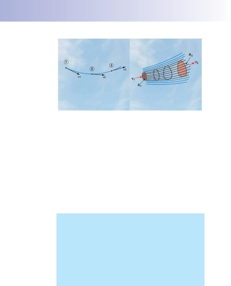
Figure 3.13 A streamline and a stream tube within a steady flow of fluid.
did, a fuid particle would be moving in two directions at once, which is impossible. In the streamline depicted in Figure 3.13, for instance, every fuid particle arriving at
Point 1 will have the velocity indicated by arrow v1. The same is true for fuid particles passing through Points 2 and 3; they will have velocities v2 and v3, respectively.
If we consider a region within a fuid fow containing a number of streamlines, we can defne that region as being a stream tube.
The Continuity Equation (Conservation of Mass).
Let us consider the steady fow of an ideal fuid through the stream tube shown in
Figure 3.13. The areas of cross sections of the stream tube at Point 1 and Point 2 are A1 and A2, respectively. The velocity of the fuid at Point 1 is v1 and the velocity of the airfow at Point 2 is v2. As the fuid is non compressible (i.e. of constant density ρ), and as there can be no fow across the streamlines, it follows that the mass of fuid fowing across the two cross sections, over any given period of time, must be the same. This principle, which is an expression of the concept of Conservation of Mass, is known as the Principle of Continuity. The Principle of Continuity is developed in the blue box below. If you are not interested in the mathematics, just skip the box.
The Principle of Continuity states that, for a stream tube, such as the one depicted in (Figure 3.13), the rate of mass fow at Point 1 must be the same as the rate of mass fow at Point 2.
Now, mass fow can be considered as mass per unit time; i.e. mass time
But density (ρ) = mass = |
|
mass |
|
|||||
|
|
Volume |
|
|
Area (A) × distance |
|
|
|
distance = velocity (v) × time |
|
|
|
|
||||
So, ρ = |
mass |
|
and, from this, |
mass = ρ × A × v |
||||
|
A × v × time |
|
|
|
|
time |
||
Therefore, |
rate of mass fow |
= ρAv |
|
|||||
46