

Measurement and Control Basics 3rd Edition (complete book)
.pdfChapter 11 – Process Control Computers |
315 |
|
Centralized Computer System |
|
Supervisor’s Console |
Supervisory |
|
Control Computer |
||
|
||
Operator’s Console |
Direct Digital Control |
|
DDC Computer |
||
|
||
Analog Backup |
Process |
|
Instrumentation |
||
|
Figure 11-5. Supervisory and direct digital control with analog backup
Distributed Control Systems
Because of the reliability problems and high cost of the control process computer systems of the 1960s, there were few new process computer projects in the early 1970s. The rare projects that were started in this period were based on medium-priced minicomputers that were designed to be small in size, and followed the block diagram shown in Figure 11-4.
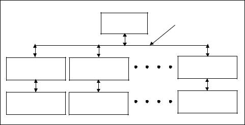
At the same time, two developments occurred in electronics that profoundly changed the application of digital computers to process control. The first was the development of integrated circuits and microprocessors. The second was the release of the distributed control system (DCS) by Honeywell in 1969. This new design concept was based on the idea of widely distributing the control to computer modules. Each of these modules controlled several instrument loops, generally one to four. They were connected by a single high-speed data communications link, called a data highway, that made possible communications between each of the computer modules and the central operator console. This design allowed the operator to monitor the operation of each local process.
In the mid-1970s, microprocessor-based modules replaced hardwired computer modules. The typical DCS had the configuration shown in Figure 11-6. Today’s distributed control systems are much more powerful and faster than the first systems because of improvements in microprocessors and other electronic circuits.
316 Measurement and Control Basics
|
Central Control |
Data Highway |
|
Console |
|
|
|
|
Microprocessor |
Microprocessor |
Microprocessor |
Based Controller 1 |
Based Controller 2 |
Based Controller n |
Process Control |
Process Control |
Process Control |
Unit 1 |
Unit 2 |
Unit n |
Figure 11-6. Microprocessor-based DCS
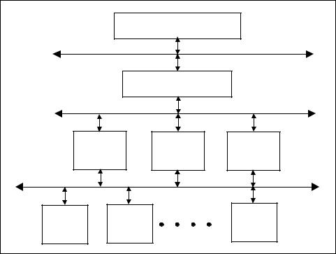
Distributed control systems today consist of one or more levels of control and information collection, as shown in Figure 11-7. The lowest level is process control and measurement on the plant floor. At this level, micro- processor-based controllers such as programmable controllers execute loop control, perform logic functions, collect and analyze process data, and communicate with other devices and to other levels in the system.
In Figure 11-7, the process data collected at level 1 is transferred to level 2. At this level, process operators and engineers use operator consoles that have a keyboard, mouse, and video display to view and adjust the various processes being controlled and monitored by the system. Also, at level 3, process and control engineers implement advanced control functions and strategies, and members of the operations management team perform advanced data collection and analysis on process information. The various plant management systems—such as inventory management and control, billing and invoicing, and statistical quality control—exist at level 3. The highest level (level 4) is used in large industrial plants to provide corporate management with extensive process and operations information.
DCS Functions and Features
The typical DCS provides a wide variety of features and functions, such as control and monitoring, an interface to operations, and advanced application software. The most important function, however, is controlling and monitoring the process.
Chapter 11 – Process Control Computers |
317 |
|
|
Executive Management System |
Level 4 |
|
Corporate Data Highway |
|
|
||
|
|
Plant Management System |
|
Level 3 |
Plant Data Highway |
|
|
||
Operator |
Process |
Supervisory |
|
|
Interface |
Engineering |
Interface |
Level 2 |
|
Consoles |
Consoles |
Consoles |
|
|
Process Highway |
|
|
|
|
Process |
|
Process |
Process |
Level 1 |
Controller |
Controller |
Controller |
||
1 |
|
2 |
n |
|
Figure 11-7. Distributed control system levels
Control and Monitoring
Process control and monitoring is performed by DCS controllers, input/ output (I/O) systems, and their associated field devices. The main control functions they perform are process interfacing, logic and interlocking, controlling analog loops, and sequencing and batch control. The most important function is handling input and output signals between the process and the DCS. This is performed by the I/O system, which consists of spe- cial-purpose electronic circuit cards that are generally mounted in metal enclosures near the process equipment. The purpose of the I/O system is to provide the signal conversions required by a wide variety of measurement devices and control elements.
The typical DCS controller provides control functions from the simplest level, pressure, temperature, and flow loops to complex strategies involving interrelated loops and advanced process calculations. Most of these control functions are part of the DCS software. The operator or engineer only needs to provide information about the I/O point or points to be controlled, and the DCS internal software performs control functions. To add further control and computational power, other specialized functions are available that make it possible to design customized control algorithms and complex calculations for unique applications.

Chapter 11 – Process Control Computers |
319 |
hardwired logic control panels. However, the modern PLC system is far more complex and powerful.
The most basic function programmable controllers perform is to examine the status of inputs and, in response, control some process or machine through outputs. The logical combination of inputs to produce an output or outputs is called control logic. Several logic combinations are usually required to carry out a control plan or program. This control plan is stored in memory using a programming device. Once input in memory, the control plan is periodically scanned by the processor--usually a high-speed microprocessor--in a predetermined sequence. The period required to examine the inputs and outputs, perform the control logic, and execute the outputs is called the scan time.
A simplified block diagram of a programmable controller is shown in Figure 11-8. In this diagram, a level switch and panel-mounted push button are wired to input circuits, and the output circuits are connected to an electric solenoid valve and a panel-mounted indicator light. The output devices are controlled by the control program in the logic unit.
L1 |
|
|
L2 |
|
|
120 vAC |
|
|
|
Level |
|
|
Solenoid |
|
|
|
Valve |
||
Switch |
|
|
||
|
|
|
||
Input |
Logic |
Output |
Panel |
|
Circuits |
Unit |
Circuits |
||
Light |
||||
|
|
|
||
Push |
|
|
|
|
Button |
|
|
|
Figure 11-8. Simplified diagram of PLC system
Figure 11-8 shows a typical configuration of the early programmable controller applications, which were intended to replace relay or hardwired logic control systems. The input circuits are used to convert the various field voltages and currents to the low-voltage signals (normally, 0 to 5 volts direct current [dc]) that are used by the logic unit. The output circuits convert the logic signals to a level that will drive the field devices. For example, in Figure 11-8, 120-volt ac power is connected to the field input

320 Measurement and Control Basics
devices, so the input circuits are used to convert the 120 Vac to the 0-to-5- volt logic signals used by the control unit.
Basic Components of PLC Systems
Regardless of size, cost, or complexity, all programmable controllers share the same basic components and functional characteristics. A programmable controller will always consist of a processor, an input/output system, a memory unit, a programming language and device, and a power supply. The block diagram in Figure 11-9 shows these five basic components, with inputs and outputs to the I/O system.
Inputs |
|
|
|
I/O |
|
|
Power |
|
|
|
|
||||
|
|
|
|
|
|
||
Outputs |
|
System |
|
|
Supply |
||
|
|
|
|||||
|
|
|
|
|
|
|
|
Processor
Programming
Memory
Device
Figure 11-9. Block diagram of a typical PLC system
The Processor
The processor consists of one or more standard or custom microprocessors as well as other integrated circuits that perform the logic, control, and memory functions of the PLC system. The processor reads the inputs, executes logic as determined by the application program, performs calculations, and controls the outputs accordingly.
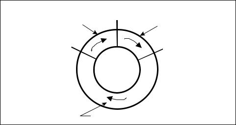
The processor controls the operating cycle or processor scan for the PLC. This operating cycle consists of a series of operations that are performed sequentially and repeatedly. Figure 11-10 shows a typical PLC processor operating cycle.
During the “input scan,” the PLC examines the external input devices to detect whether a signal is present or absent, that is, an ON or OFF state. The status of these inputs is temporarily stored in an input image table or
Chapter 11 – Process Control Computers |
321 |
Output Scan |
Start Cycle |
|
Input Scan |
||
Start |
Start Control |
|
Output Scan |
||
Program Scan |
||
|
Control Program Scan
Figure 11-10. PLC processor operating cycle
memory file. During the “program scan,” the processor scans the instructions in the control program, uses the input status from the input image file, and determines if an output will or will not be energized. The resulting status of the outputs is written to the output image table or memory file. Based on the data in the output image table, the PLC energizes or deenergizes its associated output circuits, thereby controlling external devices. This operating cycle typically takes 1 to 25 milliseconds (thousandths of a second). The input and output scans are normally very short compared to the time required for the program scan.
Memory
Memory, which is usually located in the same housing as the CPU, is used to store the control program for the PLC system. The information stored in memory determines how the input and output data will be processed.
Memory stores individual pieces of data called bits. A bit has two states: 1 or 0. Memory units are mounted on circuit boards and are usually specified in thousands or “K” increments, where 1K is 1,024 words (i.e., 210 = 1024) of storage space. The capacity of programmable controller memory may vary from less than 1,000 words to over 64,000 (64K) words, depending on the manufacturer of the programmable controller. The complexity of the control plan will determine the amount of memory required.
Although there are several different types of computer memory, they can always be classified as volatile or nonvolatile. Volatile memory will lose its programmed contents if all operating power is lost or removed. Volatile memory is easily altered and is quite suitable for most programming
322 Measurement and Control Basics
applications when it is supported by battery backup and/or a recorded copy of the program. Nonvolatile memory will retain its data and program even if there is a complete loss of operating power. It does not require a backup system.
The most common form of volatile memory is random access memory, or RAM. RAM is relatively fast and provides an easy way to create and store application programs. If normal power is disrupted, PLCs with RAM use battery or capacitor backups to prevent the loss of programs.
Electrically erasable programmable read-only memory (EEPROM) is a nonvolatile memory. It is programmed through application software running on a personal computer or through a micro-PLC handheld programmer.
The user can access two areas of memory in the PLC system: program files and data files. Program files store the control application program, subroutine files, and the error file. Data files store data associated with the control program, such as input/output status bits, counter and timer preset and accumulated values, and other stored constants or variables. Together, these two general memory areas are called user or application memory. The processor also has an executive or system memory that directs and performs operational activities such as executing the control program and coordinating input scans and output updates. The user cannot access or change this process system memory, which is programmed by the PLC manufacturer.
I/O System
The I/O system provides the physical connection between the process equipment and the microprocessor. This system uses several input circuits or modules to sense and measure the physical quantities of the process, such as motion, level, temperature, pressure, flow, and position. Based on the status it senses or the values it measures, the processor controls output modules. These modules drive field devices such as valves, motors, pumps, and alarms to exercise control over a machine or a process.
Input Types
The inputs from field instruments or sensors supply the data and information that the processor needs to make the logical decisions that control a given process or machine. These input signals come from such devices as push buttons, hand switches, thermocouples, strain gauges, and the like. These signals are connected to input modules where they are filtered and conditioned for use by the processor.
Chapter 11 – Process Control Computers |
323 |
Output Types
The outputs from the programmable logic controller energize or deenergize control devices to regulate processes or machines. These output signals are control voltages from the output circuits, and they are generally not high-power signals. For example, an output module sends a control signal that energizes the coil in a motor starter. The energized coil closes the power contacts of the starter. These contacts then close to start the motor. The output modules are usually not directly connected to the power circuit but rather to devices such as the motor starter and heater contactors that apply high-power (greater than 10 amps) signals to the final control devices.
I/O Structure
PLCs are classified as micro, small, medium, and large mainly based on the I/O count. Micro PLCs generally have an I/O count of 32 or less, small PLCs have less than 256 I/O points, medium-sized PLCs have an I/O count of less than 1,024, and large PLCs have an I/O count greater than 1,024. Micro PLCs are self-contained units in which the processor, power supply, and I/O are all in one package. Because they are self-contained, micro PLCs are also called packaged controllers. A modular PLC is one that has separate components or modules.
The advantage of a packaged controller is that the unit is smaller, costs less, and is easy to install. Figure 11-11 shows a typical wiring diagram for a micro PLC, namely, an Allen-Bradley Micro 1000 PLC with nine inputs and five outputs. The unit is powered with 120 volts of alternating current (ac). It has an internal power supply to operate the internal I/O circuits and the built-in microprocessor as well as to generate the 24 volts of direct current (dc) needed for the field input switches and contacts.
In medium and large PLC systems the I/O modules are normally installed or plugged into a slot in a “universal” modular housing. The term universal in this context means that any module can be inserted into any I/O slot in the housing. Modular I/O housings are also normally designed so that the I/O modules can be removed without turning off the ac power or removing the field wiring.
Figure 11-12 shows some typical configurations for I/O modular housings. The backplane of the housings into which the modules are plugged have a printed circuit card that contains the parallel communications bus to the processor and the dc voltages for operating the digital and analog circuits in the I/O modules. These I/O housings can be mounted in a control panel or on a subpanel in an enclosure. They are designed to protect

324 Measurement and Control Basics
|
Allen-Bradley |
|
||
|
Micro-1000 PLC |
|
||
Level |
I/O Addresses |
|
||
Switch |
I/0 |
O/0 |
M1 |
|
|
||||
Pressure |
|
|
Pump |
|
Switch |
|
|
||
I/1 |
Vac |
Starter |
||
|
||||
|
|
|
||
|
I/2 |
O/1 |
K1 |
|
Position Switch |
|
|
Heater |
|
|
I/3 |
Vac |
Contactor |
|
Pump auxiliary |
I/4 |
O/2 |
|
|
(Aux.) Contacts |
|
|
|
|
|
I/5 |
Vac |
|
|
|
|
|
||
|
|
O/5 |
|
|
Spare |
I/9 |
Vac |
|
|
|
DC Com |
|
||
|
|
L1 |
||
+24 Vdc Out |
|
H |
||
|
|
120 Vac In |
||
|
|
N |
||
|
|
L2 |
||
|
|
|
||
Figure 11-11. Typical micro-PLC wiring diagram
the I/O module circuits from dirt, dust, electrical noise, and mechanical vibration.
The backplane of the I/O chassis contains sockets for each module. These sockets provide the power and data communications connection to the processor for each module.
Discrete Inputs/Outputs
Discrete is the most common class of input/output in a programmable controller system. This type of interface module connects field devices that have two discrete states, such as ON/OFF or OPEN/CLOSED, to the processor. Each discrete I/O module is designed to be activated by a fieldsupplied voltage signal, such as +5Vdc, +24 Vdc, 120 Vac, or 220V ac.