


21 - 24 TRANSAXLE |
|
Ä |
|
Fig. 14 Remove or Install Selector Shaft |
Fig. 2 Install Differential Bearing Retainer Seal |
Fig. 15 Disassembled View
Fig. 3 Remove Differential Bearing Retainer Cup
DIFFERENTIAL BEARING RETAINER
Fig. 4 Differential Bearing Retainer
Fig. 1 Remove Differential Bearing Retainer Seal
Ä |
|
TRANSAXLE 21 - 25 |
|
Fig. 5 Install Oil Baffle |
Fig. 2 Install New Seal into Extension |
Fig. 6 Insert (Select) Shim and Differential Bearing |
Fig. 3 Remove Extension Bearing Cup |
Retainer Cup |
|
EXTENSION HOUSING |
|
Fig. 4 Extension
Fig. 1 Remove Extension Seal

21 - 26 TRANSAXLE |
|
Ä |
|
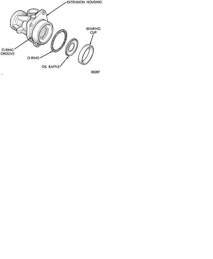
Fig. 5 Install Extension Oil Baffle
Fig. 6 Install Extension Bearing Cup
INPUT SHAFT
Shim thickness need only be determined if any of the following parts are replaced:
²Transaxle case
²Input shaft seal retainer
²Bearing retainer plate
²Rear end cover
²Input shaft
²Input shaft bearings
Refer to Bearing Adjustment Procedure in rear of this section to determine proper shim thickness for correct bearing end play and proper turning torque.
Fig. 1 Remove Input Shaft Rear Bearing Cone
Fig. 2 Install Input Shaft Rear Bearing Cone
Fig. 3 Remove Input Shaft Front Bearing Cone

Ä |
|
TRANSAXLE 21 - 27 |
|
||
|
A-523, A-543 DIFFERENTIAL |
|
|
Shim thickness need only be determined if any of |
|
|
the following parts are replaced: |
|
|
² Transaxle case |
|
|
² Differential bearing retainer |
|
|
² Extension housing |
|
|
² Differential case |
|
|
² Differential bearings |
|
|
Refer to Bearing Adjustment Procedure in rear |
|
|
of this section to determine proper shim thickness for |
|
|
correct bearing preload and proper bearing turning |
|
|
torque. |
|
Fig. 4 Install Input Shaft Front Bearing Cone
Fig. 1 Remove Differential Bearing Cone
Fig. 5 Remove Input Shaft Rear Bearing Cup
CAUTION: Bolt on bearing support plate before installing input shaft rear bearing cup.
Fig. 2 Install Differential Bearing Cone
Fig. 6 Install Input Shaft Rear Bearing Cup

21 - 28 TRANSAXLE |
|
Ä |
|
CAUTION: Always install new ring gear bolts. Bolts must be properly torqued (See Tightening Reference).
Fig. 3 Remove Differential Bearing Cone
Fig. 6 Remove Pinion Shaft Roll Pin
Fig. 4 Install Differential Bearing Cone
Fig. 7 Remove or Install Pinion Shaft
Fig. 5 Remove or Install Ring Gear Bolts and Ring
Gear
Fig. 8 Remove or Install Pinion Gears, Side Gears, and Thrust Washers by Rotating Side Gears to Opening in Case

Ä |
|
TRANSAXLE 21 - 29 |
|
Fig. 9 Differential Gears
After assembling the differential side gears, pinion gears and pinion gears with the pinion gear washers, but without the side gear thrust washers. Rotate the assembly two full revolutions both clockwise and counterclockwise.
Set up dial indicator as shown and record end play. Rotate side gear 90 degrees and record another end play. Again, rotate side gear 90 degrees and record a final end play.
Using the smallest end play recorded, shim that side gear to within .001 to .013 inch. The other side gear should be checked using the same procedure.
Fig. 10 Checking Side Gear End Play
CAUTION: Side gear end play must be within .001 to
.013 inch. Four select thrust washers are available:
.032, .037, .042, and .047 inch.
CAUTION: Side gear end play must be within .001 to
.013 inch. Four select thrust washers are available:
.032, .037, .042, and .047 inch.
Fig. 11 Checking Side Gear End Play
A-568 DIFFERENTIAL
Shim thickness need only be determined if any of the following parts are replaced:
²Transaxle case
²Differential bearing retainer
²Extension housing
²Differential case
²Differential bearings
Refer to Bearing Adjustment Procedure in rear of this section to determine proper shim thickness for correct bearing preload and proper bearing turning torque.
Fig. 1 Remove Differential Bearing Cone

21 - 30 TRANSAXLE
Fig. 2 Install Differential Bearing Cone
Fig. 3 Remove Differential Bearing Cone
Fig. 4 Install Differential Bearing Cone
Ä
Fig. 5 Remove or Install Ring Gear Bolts
CAUTION: Always install new ring gear bolts. Bolts must be properly torqued (See Tightening Reference).
Fig. 6 Remove Ring Gear
Fig. 7 Remove 3 Roll Pins
Ä |
|
TRANSAXLE 21 - 31 |
|
Fig. 8 Install 3 Roll Pins
Fig. 9 Ring Gear and Side Gear Removed
CAUTION: See Figure 12 to determine side gear thrust washer thickness. Side gear end play must be within.001 to .013 inch.
Four select thrust washes are available: .032,
.037, .042, and .047 inch.
Fig. 11 Remove or Install 4 Pinion Gears and 2 Side Gears
Fig. 12 Differential Gears
Side gear thrust washers are available in 4 select thicknesses: .032, .037, .042, and .047 inch.
Measure the depth from the differential case to the machined surface in 3 places, as shown in Figure 13. Then measure the height of raised step on the ring gear. The difference, minus the proper side gear end play (.001 to .013 inch) is the proper thrust washer thickness.
For the other side gear: After assembling the differential side gears, pinion gears, and pinion gears with the pinion gear washers but without the side gear thrust washers. Rotate the assembly two full revolutions both clockwise and counterclockwise.
Set up dial indicator as shown in Figure 14 and record end play. Rotate side gear 90 degrees and record another end play. Again, rotate side gear 90 degrees and record a final end play.
Using the smallest end play recorded, shim that side gear to within .001 to .013 inch.
Fig. 10 Remove or Install Pinion Shafts