

5.6.1: Skills Integration Challenge-Routing IP Packets
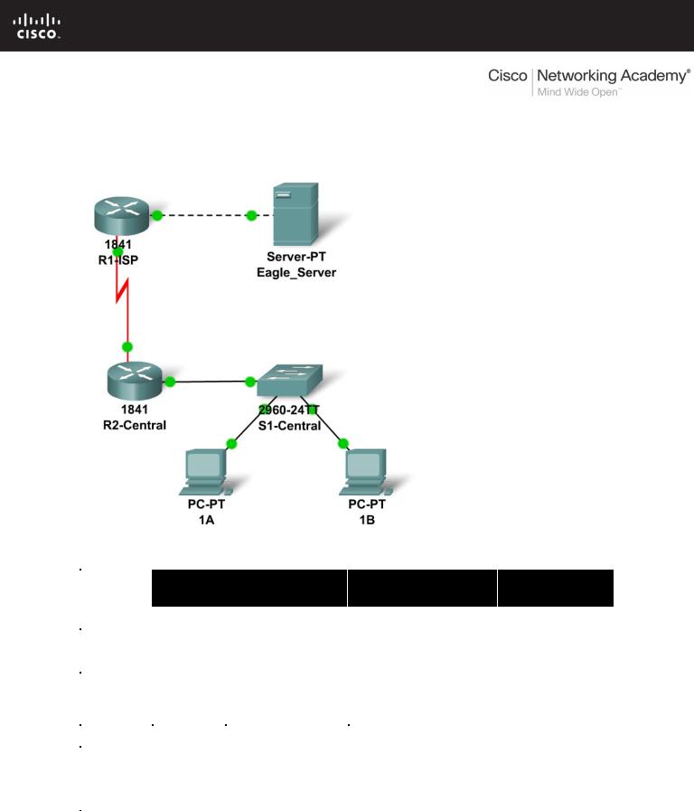
Topology Diagram
Addressing Table
|
Device |
|
Interface |
IP Address |
Subnet Mask |
Default |
|
|
Gateway |
||||
|
|
|
|
|
|
|
|
|
|
|
|
|
|
|
R1-ISP |
Fa0/0 |
192.168.254.253 |
255.255.255.0 |
N/A |
|
|
|
|
|
|
||
|
S0/0/0 |
10.10.10.6 |
255.255.255.252 |
N/A |
||
|
|
|
||||
|
|
|
|
|
|
|
|
R2- |
Fa0/0 |
172.16.255.254 |
255.255.0.0 |
10.10.10.6 |
|
|
|
|
|
|
||
|
Central |
S0/0/0 |
10.10.10.5 |
255.255.255.252 |
10.10.10.6 |
|
|
|
|
||||
|
|
|
|
|
|
|
|
S1- |
VLAN 1 |
172.16.254.1 |
255.255.0.0 |
172.16.255.254 |
|
|
Central |
|||||
|
|
|
|
|
||
|
PC 1A |
NIC |
172.16.1.1 |
255.255.0.0 |
172.16.255.254 |
|
|
|
|
||||
|
|
|
|
|
|
|
|
PC 1B |
NIC |
172.16.1.2 |
255.255.0.0 |
172.16.255.254 |
|
|
|
|
||||
|
|
|
|
|
|
|
|
Eagle |
|
|
|
|
|
|
Server |
NIC |
192.168.254.254 |
255.255.255.0 |
192.168.254.253 |
|
|
|
|
|
|
|
|
All contents are Copyright © 1992–2007 Cisco Systems, Inc. All rights reserved. This document is Cisco Public Information. |
Page 1 of 3 |

CCNA Exploration |
|
Network Fundamentals: |
|
OSI Network Layer |
5.6.1: Skills Integration Challenge-Routing IP Packets |
Learning Objectives
•Configure a router interface using a GUI.
•Explore a routing table.
•Configure a static route using a GUI.
•Explore the routing of IP packets.
Background
Throughout the course you will be using a standard lab setup created from actual PCs, servers, routers, and switches to learn networking concepts. At the end of each chapter, you will build increasingly larger parts of this topology in Packet Tracer, and analyze increasingly more complex protocol interactions. You have already studied a varieity of application protocols, such as DNS, HTTP, TFTP, DHCP, and Telnet, and two transport layer protocols, TCP and UDP. You may have noticed that regardless of what application and transport protocols were involved, in Inbound and Outbound PDU Details view they were always encapsulated in IP Packets. In this activity we will examine how the Internet Protocol, the dominant network layer protocol of the Internet, works in the context of a simple example of IP routing.
Task 1: Configure a Router Interface.
There are problems on the local area network: PC 1A cannot reach the Eagle Server (verify this in Realtime mode). It appears there is a problem with the router. Mouse over the R2-Central router, and note the condition of the Fa0/0 interface (to which switch is connected. This interface must have an IP address, subnet mask, and be turned on in order to act as the default gateway for the LAN. Click on router R2-Central, and go to the Config tab. At the end of the course, you will learn how to use the Cisco Internetwork Operating System (IOS) command line interface (CLI) to perform this task. For now, the Config tab is easier and will allow you to focus on the basic idea of IP routing. In the list shown, find INTERFACE, FastEthernet0/0. Add the IP address 172.16.255.254 with subnet mask of 255.255.0.0, and turn the port on. Close the router window. Verify that the router interface (port) is now working by using the mouse over. Try reaching Eagle Server. The request still fails. What are some possible reasons why?
Task 2: Examining Routes.
Use the Inspect Tool (magnifying glass) to examine the routing table of R2-Central. You will see the router's directly connected networks, but there is no way to reach the Eagle Server network.
Task 3: Configure a Route Using a GUI.
Click on router R2-Central and go to the Config tab. In the list shown find ROUTING, Static. Configure what is known as a default static route, using the address 0.0.0.0, mask 0.0.0.0, and the next hop of 10.10.10.6 (the S0/0/0 interface on the R1-ISP router) and click the Add button. This route is configured so that wherever packets from the 172.16.0.0 /16 LAN are destined, they will go to the R1-ISP router. Under GLOBAL, Settings, click on the Save button to save the interface and route configuration you have just done to NVRAM in case the router is power cycled. Use the Inspect Tool (magnifying glass) to examine the routing table of R2-Central again. You should now see the route you configured in the routing table.
Verify your work using feedback from the Check Results button and the Assessment Items tab. Test connectivity, in Realtime, by using ADD SIMPLE PDU to test connectivity between PC 1A and the Eagle Server. The PDU, a one-shot ping, will appear in the User Created PDU List for future use as well.
All contents are Copyright © 1992–2007 Cisco Systems, Inc. All rights reserved. This document is Cisco Public Information. |
Page 2 of 3 |

CCNA Exploration |
|
Network Fundamentals: |
|
OSI Network Layer |
5.6.1: Skills Integration Challenge-Routing IP Packets |
Task 4: Examine the Routing of the IP Packet.
Switch to Simulation mode. Using the PDU you created in Task 3, double click on Fire to send it again. Trace the packet's journey from PC 1A to Eagle Server and back using the Capture / Forward button and examining the packet's contents by either clicking on the envelope or clicking on the colored square in the Info column of the Event List.
Reflection
What data can an IP Packet contain? What is meant by the phrase "the IP packet is routed"? What is a route? Where might things go wrong?
All contents are Copyright © 1992–2007 Cisco Systems, Inc. All rights reserved. This document is Cisco Public Information. |
Page 3 of 3 |
Lab 6.7.1: Ping and Traceroute
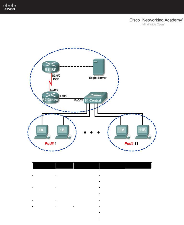
Topology Diagram
Addressing Table
|
Device |
|
Interface |
|
IP Address |
|
Subnet Mask |
|
Default Gateway |
|
|
|
|
|
|
|
|||||
|
|
|
|
|
|
|
|
|
|
|
|
R1-ISP |
|
S0/0/0 |
|
10.10.10.6 |
|
255.255.255.252 |
|
N/A |
|
|
|
|
|
|
|
|
|
|
|
|
|
|
Fa0/0 |
|
192.168.254.253 |
|
255.255.255.0 |
|
N/A |
|
|
|
|
|
|
|
|
|
||||
|
|
|
|
|
|
|
|
|
|
|
|
R2-Central |
|
S0/0/0 |
|
10.10.10.5 |
|
255.255.255.252 |
|
10.10.10.6 |
|
|
|
|
|
|
|
|
|
|
|
|
|
|
Fa0/0 |
|
172.16.255.254 |
|
255.255.0.0 |
|
N/A |
|
|
|
|
|
|
|
|
|
||||
|
|
|
|
|
|
|
|
|
|
|
|
|
|
N/A |
|
192.168.254.254 |
|
255.255.255.0 |
|
192.168.254.253 |
|
|
Eagle Server |
|
|
|
|
|
|
|||
|
|
|
|
|
|
|
|
|
|
|
|
|
N/A |
|
172.31.24.254 |
255.255.255.0 |
|
N/A |
|
||
|
|
|
|
|
|
|||||
|
|
|
|
|
|
|
||||
|
|
|
|
|
|
|
|
|
|
|
|
hostPod#A |
|
N/A |
|
172.16.Pod#.1 |
255.255.0.0 |
|
172.16.255.254 |
|
|
|
|
|
|
|
|
|||||
|
|
|
|
|
|
|
|
|
|
|
|
hostPod#B |
|
N/A |
|
172.16.Pod#.2 |
255.255.0.0 |
|
172.16.255.254 |
|
|
|
|
|
|
|
|
|||||
|
|
|
|
|
|
|
|
|
|
|
|
S1-Central |
|
N/A |
|
172.16.254.1 |
255.255.0.0 |
|
172.16.255.254 |
|
|
|
|
|
|
|
|
|||||
|
|
|
|
|
|
|
|
|
|
|
All contents are Copyright © 1992–2007 Cisco Systems, Inc. All rights reserved. This document is Cisco Public Information. Page 1 of 8
CCNA Exploration |
|
Network Fundamentals: Addressing the Network - IPV4 |
Lab 6.7.1: Ping and Traceroute |
Learning Objectives
Upon completion of this lab, you will be able to:
•Use the ping command to verify simple TCP/IP network connectivity.
•Use the tracert/traceroute command to verify TCP/IP connectivity.
Background
Two tools that are indispensable when testing TCP/IP network connectivity are ping and tracert. The ping utility is available on Windows, Linux, and Cisco IOS, and tests network connectivity. The tracert utility is available on Windows, and a similar utility, traceroute, is available on Linux and Cisco IOS. In addition to testing for connectivity, tracert can be used to check for network latency.
For example, when a web browser fails to connect to a web server, the problem can be anywhere between client and the server. A network engineer may use the ping command to test for local network connectivity or connections where there are few devices. In a complex network, the tracert command would be used. Where to begin connectivity tests has been the subject of much debate; it usually depends on the experience of the network engineer and familiarity with the network.
The Internet Control Message Protocol (ICMP) is used by both ping and tracert to send messages between devices. ICMP is a TCP/IP Network layer protocol, first defined in RFC 792, September, 1981. ICMP message types were later expanded in RFC 1700.
Scenario
In this lab, the ping and tracert commands will be examined, and command options will be used to modify the command behavior. To familiarize the students with the use of the commands, devices in the Cisco lab will be tested.
Measured delay time will probably be less than those on a production network. This is because there is little network traffic in the Eagle 1 lab.
Task 1: Use the ping Command to Verify Simple TCP/IP Network Connectivity.
The ping command is used to verify TCP/IP Network layer connectivity on the local host computer or another device in the network. The command can be used with a destination IP address or qualified name, such as eagle-server.example.com, to test domain name services (DNS) functionality. For this lab, only IP addresses will be used.
The ping operation is straightforward. The source computer sends an ICMP echo request to the destination. The destination responds with an echo reply. If there is a break between the source and destination, a router may respond with an ICMP message that the host is unknown or the destination network is unknown.
Step 1: Verify TCP/IP Network layer connectivity on the local host computer.
C:\> ipconfig
Windows IP Configuration
Ethernet adapter Local Area Connection:
Connection-specific DNS Suffix . :
IP Address. . . . . . . . . . . . : 172.16.1.2
Subnet Mask . . . . . . . . . . . : 255.255.0.0
Default Gateway . . . . . . . . . : 172.16.255.254
C:\>
Figure 1. Local TCP/IP Network Information
All contents are Copyright © 1992–2007 Cisco Systems, Inc. All rights reserved. This document is Cisco Public Information. |
Page 2 of 8 |

CCNA Exploration |
|
Network Fundamentals: Addressing the Network - IPV4 |
Lab 6.7.1: Ping and Traceroute |
1.Open a Windows terminal and determine IP address of the pod host computer with the ipconfig command, as shown in Figure 1.
The output should look the same except for the IP address. Each pod host computer should have the same network mask and default gateway address; only the IP address may differ. If the information is missing or if the subnet mask and default gateway are different, reconfigure the TCP/IP settings to match the settings for this pod host computer.
2.Record information about local TCP/IP network information:
TCP/IP Information |
Value |
IP Address |
|
Subnet Mask |
|
Default Gateway |
|
Figure 2. Output of the ping Command on the Local TCP/IP Stack
3.Use the ping command to verify TCP/IP Network layer connectivity on the local host computer.
By default, four ping requests are sent to the destination and reply information is received. Output should look similar to that shown in Figure 2.
Destination address, set to the IP address for the local computer.
Reply information:
bytes—size of the ICMP packet.
time—elapsed time between transmission and reply.
TTL—default TTL value of the DESTINATION device, minus the number of routers in the path. The maximum TTL value is 255, and for newer Windows machines the default value is 128.
Summary information about the replies:
Packets Sent—number of packets transmitted. By default, four packets are sent.
Packets Received—number of packets received.
Packets Lost —difference between number of packets sent and received.
Information about the delay in replies, measured in milliseconds. Lower round trip times indicate faster links. A computer timer is set to 10 milliseconds. Values faster than 10 milliseconds will display 0.
All contents are Copyright © 1992–2007 Cisco Systems, Inc. All rights reserved. This document is Cisco Public Information. |
Page 3 of 8 |

CCNA Exploration |
|
Network Fundamentals: Addressing the Network - IPV4 |
Lab 6.7.1: Ping and Traceroute |
4. Fill in the results of the ping command on your computer:
Field |
Value |
Size of packet
Number of packets sent
Number of replies
Number of lost packets
Minimum delay
Maximum delay
Average delay
Step 2: Verify TCP/IP Network layer connectivity on the LAN.
C:\> ping 172.16.255.254
Pinging 172.16.255.254 with 32 bytes of data:
Reply from 172.16.255.254: bytes=32 time=1ms TTL=255
Reply from 172.16.255.254: bytes=32 time<1ms TTL=255
Reply from 172.16.255.254: bytes=32 time<1ms TTL=255
Reply from 172.16.255.254: bytes=32 time<1ms TTL=255
Ping statistics for 172.16.255.254:
Packets: Sent = 4, Received = 4, Lost = 0 (0% loss),
Approximate round trip times in milli-seconds:
Minimum = 0ms, Maximum = 1ms, Average = 0ms
C:\>
Figure 3. Output of the ping Command to the Default Gateway
1.Use the ping command to verify TCP/IP Network layer connectivity to the default gateway. Results should be similar to those shown in Figure 3.
Cisco IOS default TTL value is set to 255. Because the router was not crossed, the TTL value returned is 255.
2.Fill in the results of the ping command to the default Gateway:
Field |
Value |
Size of packet
Number of packets sent
Number of replies
Number of lost packets
Minimum delay
Maximum delay
Average delay
What would be the result of a loss of connectivity to the default gateway?
___________________________________________________________________________________
All contents are Copyright © 1992–2007 Cisco Systems, Inc. All rights reserved. This document is Cisco Public Information. |
Page 4 of 8 |

CCNA Exploration |
|
Network Fundamentals: Addressing the Network - IPV4 |
Lab 6.7.1: Ping and Traceroute |
Step 3: Verify TCP/IP Network layer connectivity to a remote network.
C:\> ping 192.168.254.254
Pinging 192.168.254.254 with 32 bytes of data:
Reply from 192.168.254.254: bytes=32 time<1ms TTL=62
Reply from 192.168.254.254: bytes=32 time<1ms TTL=62
Reply from 192.168.254.254: bytes=32 time<1ms TTL=62
Reply from 192.168.254.254: bytes=32 time<1ms TTL=62
Ping statistics for 192.168.254.254:
Packets: Sent = 4, Received = 4, Lost = 0 (0% loss),
Approximate round trip times in milli-seconds:
Minimum = 0ms, Maximum = 0ms, Average = 0ms
C:\>
Figure 4. Output of the ping Command to Eagle Server
1.Use the ping command to verify TCP/IP Network layer connectivity to a device on a remote network. In this case, Eagle Server will be used. Results should be similar to those shown in Figure 4.
Linux default TTL value is set to 64. Two routers were crossed to reach Eagle Server, therefore the returned TTL value is 62.
2.Fill in the results of the ping command on your computer:
Field |
Value |
Size of packet
Number of packets sent
Number of replies
Number of lost packets
Minimum delay
Maximum delay
Average delay
C:\ > ping 192.168.254.254
Pinging 192.168.254.254 with 32 bytes of data: Request timed out.
Request timed out. Request timed out. Request timed out.
Ping statistics for 192.168.254.254:
Packets: Sent = 4, Received = 0, Lost = 4 (100% loss),
C:\>
Figure 5. Output of a ping Command with Lost Packets
The ping command is extremely useful when troubleshooting network connectivity. However, there are limitations. In Figure 5, the output shows that a user cannot reach Eagle Server. Is the problem with Eagle Server or a device in the path? The tracert command, examined next, can display network latency and path information.
All contents are Copyright © 1992–2007 Cisco Systems, Inc. All rights reserved. This document is Cisco Public Information. |
Page 5 of 8 |

CCNA Exploration |
|
Network Fundamentals: Addressing the Network - IPV4 |
Lab 6.7.1: Ping and Traceroute |
Task 2: Use the tracert Command to Verify TCP/IP Connectivity.
The tracert command is useful for learning about network latency and path information. Instead of using the ping command to test connectivity of each device to the destination, one by one, the tracert command can be used.
On Linux and Cisco IOS devices, the equivalent command is traceroute.
Step 1: Verify TCP/IP Network layer connectivity with the tracert command.
1. Open a Windows terminal and issue the following command:
C:\> tracert 192.168.254.254
C:\> tracert 192.168.254.254
Tracing route to 192.168.254.254 over a maximum of 30 hops
1 |
<1 ms |
<1 ms |
<1 ms |
172.16.255.254 |
|||
2 |
<1 |
ms |
<1 |
ms |
<1 |
ms |
10.10.10.6 |
3 |
<1 |
ms |
<1 |
ms |
<1 |
ms |
192.168.254.254 |
Trace complete.
C:\>
Figure 6. Output of the tracrt command to Eagle Server.
Output from the tracert command should be similar to that shown in Figure 6.
2. Record your result in the following table:
Field |
Value |
Maximum number of hops |
|
First router IP address |
|
Second router IP address |
|
Destination reached? |
|
Step 2: Observe tracert output to a host that lost network connectivity.
If there is a loss of connectivity to an end device such as Eagle Server, the tracert command can give valuable clues as to the source of the problem. The ping command would show the failure but not any other kind of information about the devices in the path. Referring to the Eagle 1 lab Topology Diagram, both R2-Central and R1-ISP are used for connectivity between the pod host computers and Eagle Server.
C:\> tracert -w 5 -h 4 192.168.254.254 |
|
||||
Tracing |
route to 192.168.254.254 over a |
maximum of 4 hops |
|||
1 |
<1 ms |
<1 ms |
<1 ms |
172.16.255.254 |
|
2 |
<1 ms |
<1 ms |
<1 ms |
10.10.10.6 |
|
3 |
* |
* |
* |
Request |
timed out. |
4 |
* |
* |
* |
Request |
timed out. |
Trace complete.
C:\>
Figure 7. Output of the tracert Command
Refer to Figure 7. Options are used with the tracert command to reduce wait time (in milliseconds), -w 5, and maximum hop count, -h 4. If Eagle Server was disconnected from the network, the default gateway would respond correctly, as well as R1-ISP. The problem must be on the 192.168.254.0/24 network. In this example, Eagle Server has been turned off.
All contents are Copyright © 1992–2007 Cisco Systems, Inc. All rights reserved. This document is Cisco Public Information. |
Page 6 of 8 |

CCNA Exploration |
|
Network Fundamentals: Addressing the Network - IPV4 |
Lab 6.7.1: Ping and Traceroute |
What would the tracert output be if R1-ISP failed?
___________________________________________________________________________________
What would the tracert output be if R2-Central failed?
___________________________________________________________________________________
Task 3: Challenge
The default values for the ping command normally work for most troubleshooting scenarios. There are times, however, when fine tuning ping options may be useful. Issuing the ping command without any destination address will display the options shown in Figure 8:
C:\> ping
Usage: ping [-t] [-a] [-n count] [-l size] [-f] [-i TTL] [-v TOS]
|
|
[-r count] [-s count] [[-j host-list] | [-k host-list]] |
|||||
|
|
[-w timeout] target_name |
|||||
Options: |
|
|
|
|
|
||
|
-t |
|
Ping the specified host until stopped. |
|
|||
|
|
|
To see statistics and continue - type Control- |
||||
Break; |
|
|
|
|
|
|
|
|
|
|
To stop - type Control-C. |
||||
|
-a |
|
Resolve addresses to hostnames. |
|
|
||
|
|
|
|
|
|
|
|
|
-n |
count |
Number of echo requests to send. |
|
|||
|
-l |
size |
Send buffer size. |
|
|||
|
-f |
|
Set Don't Fragment flag in packet. |
||||
|
-i |
TTL |
Time To Live. |
||||
|
-v |
TOS |
Type Of Service. |
||||
|
-r |
count |
Record route for count hops. |
||||
|
-s |
count |
Timestamp for count hops. |
||||
|
-j |
host-list |
Loose source route along host-list. |
||||
|
-k |
host-list |
Strict source route along host-list. |
||||
|
-w |
timeout |
Timeout in milliseconds to wait for each reply. |
||||
C:\> |
|
|
|
|
|
|
|
Figure 8. Output of a ping Command with no Destination Address
The most useful options are highlighted in yellow. Some options do not work together, such as the –t and –n options. Other options can be used together. Experiment with the following options:
All contents are Copyright © 1992–2007 Cisco Systems, Inc. All rights reserved. This document is Cisco Public Information. |
Page 7 of 8 |

CCNA Exploration |
|
Network Fundamentals: Addressing the Network - IPV4 |
Lab 6.7.1: Ping and Traceroute |
To ping the destination address until stopped, use the –t option. To stop, press <CTRL> C:
C:\> ping –t 192.168.254.254
Pinging 192.168.254.254 with 32 bytes of data:
Reply from 192.168.254.254: bytes=32 time<1ms TTL=63 Reply from 192.168.254.254: bytes=32 time<1ms TTL=63 Reply from 192.168.254.254: bytes=32 time<1ms TTL=63 Reply from 192.168.254.254: bytes=32 time<1ms TTL=63 Reply from 192.168.254.254: bytes=32 time<1ms TTL=63 Reply from 192.168.254.254: bytes=32 time<1ms TTL=63 Ping statistics for 192.168.254.254:
Packets: Sent = 6, Received = 6, Lost = 0 (0% loss), Approximate round trip times in milli-seconds:
Minimum = 0ms, Maximum = 0ms, Average = 0ms Control-C
^C
C:\>
Figure 9. Output of a ping Command using the –t Option
To ping the destination once, and record router hops, use the –n and –r options, as shown in Figure 10. Note: Not all devices will honor the –r option.
C:\> ping -n 1 –r 9 192.168.254.254
Pinging 192.168.254.254 with 32 bytes of data:
Reply from 192.168.254.254: bytes=32 time=1ms TTL=63 Route: 10.10.10.5 ->
192.168.254.253 -> 192.168.254.254 -> 10.10.10.6 ->
172.16.255.254
Ping statistics for 192.168.254.254:
Packets: Sent = 1, Received = 1, Lost = 0 (0% loss), Approximate round trip times in milli-seconds:
Minimum = 1ms, Maximum = 1ms, Average = 1ms
C:\>
Figure 10. Output of a ping Command using the –n and –r Options
Task 4: Reflection
Both ping and tracert are used by network engineers to test network connectivity. For basic network connectivity, the ping command works best. To test latency and the network path, the tracert command is preferred.
The ability to accurately and quickly diagnose network connectivity issues is a skill expected from a network engineer. Knowledge about the TCP/IP protocols and practice with troubleshooting commands will build that skill.
Task 5: Clean Up
Unless directed otherwise by the instructor, turn off power to the host computers. Remove anything that was brought into the lab, and leave the room ready for the next class.
All contents are Copyright © 1992–2007 Cisco Systems, Inc. All rights reserved. This document is Cisco Public Information. |
Page 8 of 8 |