

- •Activity 1.1.1: Using Google Earth™ to View the World
- •Activity 1.4.5: Identifying Top Security Vulnerabilities
- •Lab 1.6.1: Using Collaboration Tools— IRC and IM
- •Lab 1.6.2: Using Collaboration Tools—Wikis and Web Logs
- •1.7.1: Skills Integration Challenge-Introduction to Packet Tracer
- •Activity 2.2.5: Using NeoTrace™ to View Internetworks
- •Lab 2.6.1: Topology Orientation and Building a Small Network
- •Lab 2.6.2: Using Wireshark™ to View Protocol Data Units
- •2.7.1: Skills Integration Challenge-Examining Packets
- •Activity 3.4.1: Data Stream Capture
- •Lab 3.4.2: Managing a Web Server
- •Lab 3.4.3: E-mail Services and Protocols
- •Lab 4.5.1: Observing TCP and UDP using Netstat
- •Lab 4.5.2: TCP/IP Transport Layer Protocols, TCP and UDP
- •Lab 4.5.3: Application and Transport Layer Protocols Examination
- •Lab 5.5.1: Examining a Device’s Gateway
- •Lab 5.5.2: Examining a Route
- •5.6.1: Skills Integration Challenge-Routing IP Packets
- •Lab 6.7.1: Ping and Traceroute
- •Lab 6.7.2: Examining ICMP Packets
- •Activity 6.7.3: IPv4 Address Subnetting Part 1
- •Activity 6.7.4: IPv4 Address Subnetting Part 2
- •Lab 6.7.5: Subnet and Router Configuration
- •Lab 7.5.2: Frame Examination
- •7.6.1: Skills Integration Challenge-Data Link Layer Issues
- •Lab 8.4.1: Media Connectors Lab Activity
- •Lab 9.8.1: Address Resolution Protocol (ARP)
- •Lab 9.8.2: Cisco Switch MAC Table Examination
- •Lab 9.8.3: Intermediary Device as an End Device
- •9.9.1: Skills Integration Challenge-Switched Ethernet
- •Lab 10.3.2: How Many Networks?
- •Lab 10.6.1: Creating a Small Lab Topology
- •Lab 10.6.2: Establishing a Console Session with HyperTerminal
- •Lab 10.6.3: Establishing a Console Session with Minicom
- •11.4.3.3: Network Latency Documentation with Ping
- •Lab 11.5.1: Basic Cisco Device Configuration
- •Lab 11.5.2: Managing Device Configuration
- •Lab 11.5.3: Configure Host Computers for IP Networking
- •Lab 11.5.4: Network Testing
- •Lab 11.5.5: Network Documentation with Utility Commands
- •Lab 11.5.6: Final Case Study - Datagram Analysis with Wireshark
Lab 11.5.6: Final Case Study - Datagram Analysis with Wireshark
Learning Objectives
Upon completion of this exercise, students will be able to demonstrate:
•How a TCP segment is constructed, and explain the segment fields.
•How an IP packet is constructed, and explain the packet fields.
•How an Ethernet II frame is constructed, and explain the frame fields.
•Contents of an ARP REQUEST and ARP REPLY.
Background
This lab requires two captured packet files and Wireshark, a network protocol analyzer. Download the following files from Eagle server, and install Wireshark on your computer if it is not already installed:
•eagle1_web_client.pcap (discussed)
•eagle1_web_server.pcap (reference only)
•wireshark.exe
Scenario
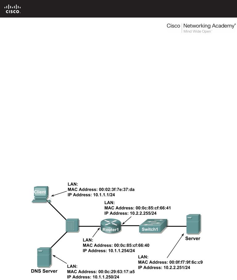
This exercise details the sequence of datagrams that are created and sent across a network between a web client, PC_Client, and web server, eagle1.example.com. Understanding the process involved in sequentially placing packets on the network will enable the student to logically troubleshoot network failures when connectivity breaks. For brevity and clarity, network packet noise has been omitted from the captures. Before executing a network protocol analyzer on a network that belongs to someone else, be sure to get permissionin writing.
Figure 1 shows the topology of this lab.
Figure 1. Network Topology.
All contents are Copyright © 1992–2007 Cisco Systems, Inc. All rights reserved. This document is Cisco Public Information. |
Page 1 of 9 |
CCNA Exploration |
|
Network Fundamentals: |
|
Configuring and Testing Your Network |
Lab 11.5.6: Final Case Study - Datagram Analysis with Wireshark |
Using Microsoft ® command line tools, IP configuration information and the contents of ARP cache are displayed. Refer to Figure 2.
C: > ipconfig / all
Windows IP Configuration
Ethernet adapter Local Area Connection: Connection-specific DNS Suffix . :
Description . . . . . . . . . . . : Intel(R) PRO/1000 MT Network Connection
Physical Address. . . . . . . . . : 00:02:3f:7e:37:da Dhcp Enabled. . . . . . . . . . . : No
IP Address. . . . . . . . . . . . : 10.1.1.1 Subnet Mask . . . . . . . . . . . : 255.255.255.0 Default Gateway . . . . . . . . . : 10.1.1.254 DNS Servers . . . . . . . . . . . : 10.1.1.250
C: > arp –a
No ARP Entries Found C: >
Figure 2. PC Client initial network state.
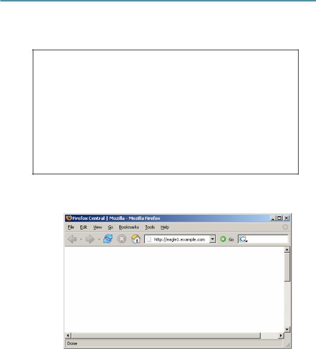
A web client is started, and URL eagle1.example.com is entered, as shown in Figure 3. This begins the communication process to the web server, and where the captured packets start.
Figure 3. PC Client with web browser.
Task 1: Prepare the Lab.
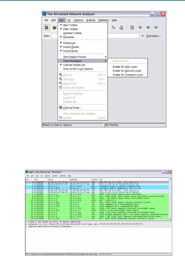
Step 1: Start Wireshark on your computer.
Refer to Figure 4 for changes to the default output. Uncheck Main toolbar, Filter toolbar, and Packet Bytes. Verify that Packet List and Packet Details are checked. To insure there is no automatic translation in MAC addresses, de-select Name Resolution for MAC layer and Transport Layer.
All contents are Copyright © 1992–2007 Cisco Systems, Inc. All rights reserved. This document is Cisco Public Information. |
Page 2 of 9 |
CCNA Exploration |
|
Network Fundamentals: |
|
Configuring and Testing Your Network |
Lab 11.5.6: Final Case Study - Datagram Analysis with Wireshark |
Figure 4. Wireshark default view changes.
Step 2: Load the web client capture, eagle1_web_client.pcap.
A screen similar to Figure 5 will be displayed. Various pull-down menus and sub-menus are available. There are also two separate data windows. The top Wireshark window lists all captured packets. The bottom window contains packet details. In the bottom window, each line that contains a check box, indicates that additional information is available.
Figure 5. Wireshark with file eagle1_web_client.pcap loaded.
All contents are Copyright © 1992–2007 Cisco Systems, Inc. All rights reserved. This document is Cisco Public Information. |
Page 3 of 9 |

CCNA Exploration |
|
Network Fundamentals: |
|
Configuring and Testing Your Network |
Lab 11.5.6: Final Case Study - Datagram Analysis with Wireshark |
Task 2: Review the Process of Data Flowing through the Network.
Step 1: Review Transport layer operation.
When PC_Client builds the datagram for a connection with eagle1.example.com, the datagram travels down the various network Layers. At each Layer, important header information is added. Because this communication is from a web client, the Transport Layer protocol will be TCP. Consider the TCP segment, shown in Figure 6. PC_Client generates an internal TCP port address, in this conversation 1085, and knows the well-known web server port address, 80. Likewise, a sequence number has been internally generated. Data is included, provided by the Application Layer. Some information will not be known to PC_Client, so it must be discovered using other network protocols.
There is no acknowledgement number. Before this segment can move to the Network Layer, the TCP threeway handshake must be performed.
|
|
|
|
TCP Segment |
|
|
0 |
4 |
7 |
10 |
16 |
31 |
|
|
Source Port |
|
|
|
Destination Port |
|
|
|
|
|
Sequence Number |
|
|
|
|
|
|
Acknowledgement Number |
|
|
Data Offset |
Reserved |
ECN |
|
Control Bits |
|
Window |
|
Checksum |
|
|
|
Urgent Pointer |
|
|
|
|
|
Options and Padding |
|
|
|
|
|
|
Data |
|
|
Figure 6. TCP Segment fields.
Step 2: Review Network layer operation.
At the Network Layer, the IPv4 (IP) PACKET has several fields ready with information. This is shown in Figure 7. For example, the packet Version (IPv4) is known, as well as the source IP address.
The destination for this packet is eagle1.example.com. The corresponding IP Address must be discovered through DNS (Domain Name Services). Until the upper layer datagram is received, fields related to the upper layer protocols are empty.
|
|
|
|
|
|
IP Packet |
|
|
0 |
4 |
8 |
10 |
16 |
31 |
|||
|
Version |
|
IHL |
|
|
TOS |
|
Total Length |
|
|
|
Identification |
|
Flags |
Fragment Offset |
||
|
TTL |
|
|
|
Protocol |
|
Header Checksum |
|
|
|
|
|
|
|
Source IP Address |
|
|
|
|
|
|
|
|
Destination IP Address |
|
|
|
|
|
|
|
|
Data |
|
|
Figure 7. IP Packet fields.
All contents are Copyright © 1992–2007 Cisco Systems, Inc. All rights reserved. This document is Cisco Public Information. |
Page 4 of 9 |

CCNA Exploration |
|
Network Fundamentals: |
|
Configuring and Testing Your Network |
Lab 11.5.6: Final Case Study - Datagram Analysis with Wireshark |
Step 3: Review Data Link layer operation.
Before the datagram is placed on the physical medium, it must be encapsulated inside a frame. This is shown in Figure 8. PC_Client has knowledge of the source MAC address, but must discover the destination MAC address.
The destination MAC address must be discovered.
|
|
Ethernet II Frame Format |
|
|
||
Preamble |
Destination |
Source |
Frame |
Data |
CRC |
|
Address |
||||||
|
Address |
Type |
|
|
||
|
|
|
|
|||
|
|
|
|
|
|
|
8 Octets |
6 Octets |
6 Octets |
2 Octets |
46-1500 Octets |
4 Octets |
|
|
|
|
|
|
|
|
Figure 8. Ethernet II frame fields.
Task 3: Analyze Captured Packets.
Step 1: Review the data flow sequence.
A review of missing information will be helpful in following the captured packet sequence:
a.The TCP segment cannot be constructed because the acknowledgement field is blank. A TCP 3- way handshake with eagle1.example.com must first be completed.
b.The TCP 3-way handshake cannot occur because PC_Client does not know the IP address for eagle1.example.com. This is resolved with a DNS request from PC_Client to the DNS the server.
c.The DNS server cannot be queried because the MAC address for the DNS server is not known. The ARP protocol is broadcast on the LAN to discover the MAC address for the DNS server.
d.The MAC address for eagle1.example.com is unknown. The ARP protocol is broadcast on the LAN to learn the destination MAC address for eagle1.example.com.
Step 2: Examine the ARP request.
Refer to Wireshark, Packet List window, No. 1. The captured frame is an ARP (Address Resolution Protocol) Request. Contents of the Ethernet II frame can be viewed by clicking on the check box in the second line of the Packet Details window. Contents of the ARP Request can be viewed by clicking on the ARP Request line in the Packet Details window.
1.What is the source MAC address for the ARP Request? _____________________
2.What is the destination MAC address for the ARP Request? _____________________
3.What is the unknown IP address in the ARP Request? ______________________
4.What is the Ethernet II Frame Type? _____________________
All contents are Copyright © 1992–2007 Cisco Systems, Inc. All rights reserved. This document is Cisco Public Information. |
Page 5 of 9 |

CCNA Exploration |
|
Network Fundamentals: |
|
Configuring and Testing Your Network |
Lab 11.5.6: Final Case Study - Datagram Analysis with Wireshark |
Step 3: Examine the ARP reply.
Refer to Wireshark, Packet List window, No. 2. The DNS server sent an ARP Reply.
1.What is the source MAC address for the ARP Reply? _____________________
2.What is the destination MAC address for the ARP Request? _____________________
3.What is the Ethernet II Frame Type? _____________________
4.What is the destination IP address in the ARP Reply? _____________________
5.Based on the observation of the ARP protocol, what can be inferred about an ARP Request destination address and an ARP Reply destination address?
_____________________________________________________________________
_____________________________________________________________________
_____________________________________________________________________
6.Why did the DNS server not have to send an ARP Request for the PC_Client MAC address?
_____________________________________________________________
_____________________________________________________________________
Step 4: Examine the DNS query.
Refer to Wireshark, Packet List window, No. 3. PC_Client sent a DNS query to the DNS server. Using the Packet Details window, answer the following questions:
1.What is the Ethernet II Frame Type? _____________________
2.What is the Transport Layer protocol, and what is the destination port number?
_____________________
Step 5: Examine the DNS query response.
Refer to Wireshark, Packet List window, No. 4. The DNS server sent a DNS query response to PC_Client. Using the Packet Details window, answer the following questions:
1.What is the Ethernet II Frame Type? _____________________
2.What is the Transport Layer protocol, and what is the destination port number?
_____________________
3.What is the IP address for eagle1.example.com? _____________________
4.A colleague is a firewall administrator, and asked if you thought of any reason why all UDP packets should not be blocked from entering the internal network. What is your response?
_____________________
_____________________________________________________________________
_____________________________________________________________________
_____________________________________________________________________
All contents are Copyright © 1992–2007 Cisco Systems, Inc. All rights reserved. This document is Cisco Public Information. |
Page 6 of 9 |

CCNA Exploration |
|
Network Fundamentals: |
|
Configuring and Testing Your Network |
Lab 11.5.6: Final Case Study - Datagram Analysis with Wireshark |
Step 6: Examine the ARP request.
Refer to Wireshark, Packet List window, No. 5 and No 6. PC_Client sent an ARP Request to IP address 10.1.1.254.
1.Is this IP address different than the IP address for eagle1.example.com? Explain?
____________________________________________________________________
____________________________________________________________________
Step 7: Examine the TCP 3-way handshake.
Refer to Wireshark, Packet List window, No. 7, No. 8, and No. 9. These captures contain the TCP 3-way handshake between PC_Client and eagle1.example.com. Initially, only the TCP SYN flag is set on the datagram sent from PC_Client, sequence number 0. eagle1.example.com responds with the TCP ACK and SYN flags set, along with an acknowledgement of 1 and sequence of 0. In the Packet List window, there is an unexplained value, MSS=1460. MSS stands for Maximum Segment size. When a TCP segment is transported over IPv4, MSS is computed to be the maximum size of an IPv4 datagram minus 40 bytes. This value is sent during connection startup. This is also when TCP sliding windows are negotiated.
1.If the initial TCP sequence value from PC_Client is 0, why did eagle1.example respond with an acknowledgement of 1?
____________________________________________________________________
____________________________________________________________________
2.In eagle1.example.com, No. 8, What does the IP Flag value of 0x04 mean?
____________________________________________________________________
3.When PC_Client completes the TCP 3-way handshake, Wireshark Packet List No 9, what are the TCP flag states returned to eagle1.example.com?
____________________________________________________________________
Task 4: Complete the Final Analysis.
Step 1: Match the Wireshark output to the process.
It has taken a total of nine datagrams sent between PC_Client, DNS server, Gateway, and eagle1.example.com before PC_Client has sufficient information to send the original web client request to eagle1.example.com. This is shown in Wireshark Packet List No. 10, where PC_Client sent a web protocol GET request.
1.Fill in the correct Wireshark Packet List number that satisfies each of the following missing entries:
a.The TCP segment cannot be constructed because the acknowledgement field is blank. A TCP 3-way handshake with eagle1.example.com must first be completed. ________
All contents are Copyright © 1992–2007 Cisco Systems, Inc. All rights reserved. This document is Cisco Public Information. |
Page 7 of 9 |

CCNA Exploration |
|
Network Fundamentals: |
|
Configuring and Testing Your Network |
Lab 11.5.6: Final Case Study - Datagram Analysis with Wireshark |
b.The TCP 3-way handshake cannot occur because PC_Client does not know the IP address for eagle1.example.com. This is resolved with a DNS request from PC_Client to the DNS the server. ________
c.The DNS server cannot be queried because the MAC address for the DNS server is not known. The ARP protocol is broadcast on the LAN to discover the MAC address for the DNS server.
________
d.The MAC address for the gateway to reach eagle1.example.com is unknown. The ARP protocol is broadcast on the LAN to learn the destination MAC address for the gateway. ________
1.Wireshark Packet List No. 11 is an acknowledgement from eagle1.example.com to the PC_Client GET request, Wireshark Packet List No. 10.
2.Wireshark Packet List No. 12, 13 and 15 are TCP segments from eagle1.example.com. Wireshark Packet List No. 14 and 16 are ACK datagrams from PC_Client.
3.To verify the ACK, highlight Wireshark Packet List No. 14. Next, scroll down to the bottom of the detail list window, and expand the [SEQ/ACK analysis] frame. The ACK datagram for Wireshark Packet List No. 14 is a response to which datagram from eagle1.example.com? _______________
4.Wireshark Packet List No. 17 datagram is sent from PC_Client to eagle1.example.com. Review the information inside the [SEQ/ACK analysis] frame. What is the purpose of this datagram?
5.When PC_Client is finished, TCP ACK and FIN flags are sent, shown in Wireshark Packet List No. 18. eagle1.example.com responds with a TCP ACK, and the TCP session is closed.
Step 2: Use Wireshark TCP Stream.
Analyzing packet contents can be a daunting experience, time consuming and error prone. Wireshark includes an option that constructs the TCP Stream in a separate window. To use this feature, first select a TCP datagram from the Wireshark Packet List. Next, select Wireshark menu options Analyze | Follow TCP Stream. A window similar to Figure 9 will be displayed.
All contents are Copyright © 1992–2007 Cisco Systems, Inc. All rights reserved. This document is Cisco Public Information. |
Page 8 of 9 |

CCNA Exploration |
|
Network Fundamentals: |
|
Configuring and Testing Your Network |
Lab 11.5.6: Final Case Study - Datagram Analysis with Wireshark |
Figure 9. Output of the TCP stream.
Task 5: Conclusion
Using a network protocol analyzer can serve as an effective learning tool for understanding critical elements of network communication. Once the network administrator is familiar with communication protocols, the same protocol analyzer can become an effective troubleshooting tool when there is network failure. For example, if a web browser could not connect to a web server there could be multiple causes. A protocol analyzer will show unsuccessful ARP requests, unsuccessful DNS queries, and unacknowledged packets.
Task 6: Summary
In this exercise the student has learned how communication between a web client and web server communicate. Behind-the-scene protocols such as DNS and ARP are used to fill in missing parts of IP packets and Ethernet frames, respectively. Before TCP session can begin, the TCP 3-way handshake must build a reliable path and supply both communicating ends with initial TCP header information. Finally, the TCP session is destroyed in an orderly manner with the client issuing a TCP FIN flag.
All contents are Copyright © 1992–2007 Cisco Systems, Inc. All rights reserved. This document is Cisco Public Information. |
Page 9 of 9 |
11.6.1: Skills Integration Challenge-Configuring and Testing the
Lab Network
Topology Diagram
Addressing Table
|
Device |
|
Interface |
IP Address |
Subnet Mask |
Default |
|
|
Gateway |
||||
|
|
|
|
|
|
|
|
|
|
|
|
|
|
|
R1-ISP |
Fa0/0 |
|
|
N/A |
|
|
|
|
|
|
||
|
S0/0/0 |
|
|
N/A |
||
|
|
|
|
|
||
|
|
|
|
|
|
|
|
R2- |
Fa0/0 |
|
|
|
|
|
|
|
|
|
||
|
Central |
S0/0/0 |
|
|
|
|
|
|
|
|
|
|
|
|
|
|
|
|
|
|
|
PC 1A |
NIC |
|
|
|
|
|
|
|
|
|
|
|
|
|
|
|
|
|
|
|
PC 1B |
NIC |
|
|
|
|
|
|
|
|
|
|
|
|
|
|
|
|
|
|
|
Eagle |
|
|
|
|
|
|
Server |
NIC |
|
|
|
|
|
|
|
|
|
|
|
All contents are Copyright © 1992–2007 Cisco Systems, Inc. All rights reserved. This document is Cisco Public Information. |
Page 1 of 4 |

CCNA Exploration |
|
Network Fundamentals: |
|
Configuring and Testing Your Network |
11.6.1: Skills Integration Challenge-Configuring and Testing the Lab Network |
Learning Objectives
•Build, test, and configure the entire lab network.
oIntegrate skills from throughout the course.
•Analzye the events involved in:
oRequesting a web page (DNS, ARP, HTTP, TCP, IP, Ethernet, HDLC).
oTracing the route to the web server (DNS, UDP, ARP, ICMP, IP, Ethernet, HDLC)
Background
Throughout the course, you have been developing network planning, building, configuring, and testing skills. You have also developed conceptual understandings of networking protocols and device algorithms. Here is an opportunity to test yourself: see if you can complete the entire challenge (approximately 100 configurable components, though some are quite easy) in under 30 minutes.
Task 1: Plan.
Use the standard Exploration lab topology as you plan your IP addressing scheme:
•Two 1841 routers with WIC-2T interface cards, installed in the right hand slot (one named R1-ISP, which has the serial DCE WAN connection to R2-Central, and the Fa0/0 LAN connection to Eagle_Server) and one named R2-Central (which has the serial DCE WAN connection to R1-ISP and the Fa0/0 LAN connection to S1-Central)
•One 2960TT Switch (S1-Central)
•Two PCs named 1A and 1B
•A server named Eagle_Server.
Note that both the Display names AND host names for all devices must be configured exactly, and in general all strings (names, passwords, banners) should be typed exactly as specified in these instructions, for the grading to work properly.
You have been given an IP address block of 192.168.3.0 /24. You must provide for existing networks as well as future growth.
Subnet assignments are:
•1st subnet, existing student LAN, up to 28 hosts (Fa0/0 on R2-Central, connected to Fa0/24 on S1-Central)
•2nd subnet, future student LAN, up to 28 hosts (not yet implemented)
•3rd subnet, existing ISP LAN, up to 14 hosts (Fa0/0 on R1-ISP)
•4th subnet, future ISP LAN, up to 7 hosts (not yet implemented)
•5th subnet, existing WAN, point-to-point link (S0/0/0 on R1-ISP and S0/0/0 on R2Central)
All contents are Copyright © 1992–2007 Cisco Systems, Inc. All rights reserved. This document is Cisco Public Information. |
Page 2 of 4 |

CCNA Exploration |
|
Network Fundamentals: |
|
Configuring and Testing Your Network |
11.6.1: Skills Integration Challenge-Configuring and Testing the Lab Network |
IP address assignments are:
•For the server, configure the second highest usable IP address on the ISP LAN subnet.
•For R1-ISP's Fa0/0 interface, configure the highest usable IP address on the ISP LAN subnet.
•For R1-ISP's S0/0/0 interface, configure the highest usable address on the existing WAN subnet.
•For R2-Central's S0/0/0 interface, use the lowest usable address on the existing WAN subnet.
•For R2-Central's Fa0/0 interface, use the highest usable address on the existing student LAN subnet and connect it to the Fa0/24 interface on S1-Central.
•For hosts 1A and 1B, use the first 2 IP addresses (two lowest usable addresses) on the existing student LAN subnet and connect them to the Fa0/1 and Fa0/2 interfaces on S1Central.
•For the switch management interface, use the second highest usable address on the student subnet.
Task 2: Build and Configure the Network.
Build the network, taking care to make connections as specified. Configure both routers, the switch, the server, and the two PCs.
Configure the routers using the CLI to practice your skills. The router configuration must include "housekeeping" (display name, hostname, passwords, banner), interfaces (Fast Ethernet and Serial), and routing (static route on R1-ISP, default route on R2-Central). The following login passwords should all be set to "cisco" (no quotes): enable, console, and Telnet. The banners should say **This is lab router R1-ISP. Authorized access only.** and **This is lab router R2Central. Authorized access only.**
The interfaces should be configured as specified in the IP addressing section above; use a clock rate of 64000 on the R1-ISP S0/0/0 interface. The static route on R1-ISP should point to the existing Student LAN subnet via R2-Central's serial interface IP address; the static route on R2Central should be a default static route which points via R1-ISP's serial interface IP address. Whenever you configure a Cisco IOS device, be sure to save your configuration.
On the switch, configure the display name, hostname, banner (**This is lab switch S1-Central. Authorized access only.**), login passwords for access (enable, console, and Telnet passwords all set to "cisco"), and management interface (int vlan1). Whenever you configure a Cisco IOS device, be sure to save your configuration.
For Hosts 1A and 1B, in addition to IP configuration, configure them to use DNS services. For the server, enable DNS services, use the domain name eagle-server.example.com, and enable HTTP services.
As you work, use "Check Results" to see what components still need to be configured. If you want more practice, use "Reset Activity" and re-time yourself doing the entire configuration again.
All contents are Copyright © 1992–2007 Cisco Systems, Inc. All rights reserved. This document is Cisco Public Information. |
Page 3 of 4 |

CCNA Exploration |
|
Network Fundamentals: |
|
Configuring and Testing Your Network |
11.6.1: Skills Integration Challenge-Configuring and Testing the Lab Network |
Task 3: Test and Analzye.
It is a good practice to test connectivity through ping and Telnet, and to examine routing tables. Once you are convinced your network is working, make sure you have saved your configurations on the Cisco IOS devices. Then power cycle the devices, and reset the network. In simulation mode, request a web page while making the following protocols visible in the event list: DNS, HTTP, Telnet, TCP, UDP, ICMP, ARP. Examine the packets as they are processed by the devices to study protocol behavior, especially how IP is involved in everything. Also note the algorithms used by hosts, switches, and routers. Explain the entire process to a peer. Power cycle the devices to clear the network again, and, also in simulation mode, issue a traceroute to the server from one of the PCs. Examine how trace is built up of ICMP echo requests. Again explain the entire process to a peer.
Reflection
Relate the processes observed in Task 3 to the TCP/IP Protocol Graph. Your skills at modeling networks in Packet Tracer will serve you well in subsequent courses.
All contents are Copyright © 1992–2007 Cisco Systems, Inc. All rights reserved. This document is Cisco Public Information. |
Page 4 of 4 |