

Lab 7.5.2: Frame Examination
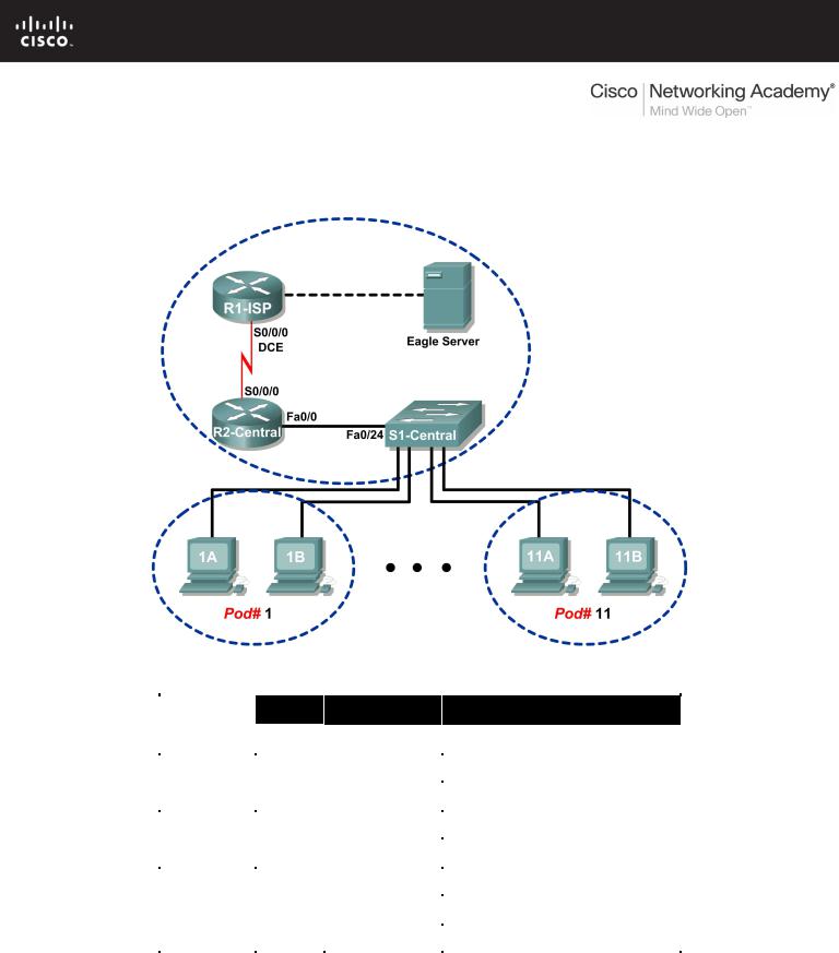
Topology Diagram
Addressing Table
Device |
Interface |
IP Address |
Subnet Mask |
Default Gateway |
|
|
|
|
|
|
|
R1-ISP |
S0/0/0 |
10.10.10.6 |
255.255.255.252 |
N/A |
|
|
|
|
|
||
Fa0/0 |
192.168.254.253 |
255.255.255.0 |
N/A |
||
|
|||||
|
|
|
|
|
|
R2-Central |
S0/0/0 |
10.10.10.5 |
255.255.255.252 |
10.10.10.6 |
|
|
|
|
|
||
Fa0/0 |
172.16.255.254 |
255.255.0.0 |
N/A |
||
|
|||||
|
|
|
|
|
|
|
N/A |
192.168.254.254 |
255.255.255.0 |
192.168.254.253 |
|
Eagle Server |
|
||||
|
|
|
|
||
N/A |
172.31.24.254 |
255.255.255.0 |
N/A |
||
|
|
||||
|
|
|
|
|
|
hostPod#A |
N/A |
172.16.Pod#.1 |
255.255.0.0 |
172.16.255.254 |
|
|
|||||
|
|
|
|
|
|
hostPod#B |
N/A |
172.16.Pod#.2 |
255.255.0.0 |
172.16.255.254 |
|
|
|||||
|
|
|
|
|
|
S1-Central |
N/A |
172.16.254.1 |
255.255.0.0 |
172.16.255.254 |
|
|
|||||
|
|
|
|
|
All contents are Copyright © 1992–2007 Cisco Systems, Inc. All rights reserved. This document is Cisco Public Information. |
Page 1 of 7 |
CCNA Exploration |
|
Network Fundamentals: Data Link Layer |
Lab 7.5.2 Frame Examination |
Learning Objectives
Upon completion of this lab, you will be able to:
•Explain the header fields in an Ethernet II frame.
•Use Wireshark to capture and analyze Ethernet II frames.
Background
When upper layer protocols communicate with each other, data flows down the OSI layers and is encapsulated into a Layer 2 frame. The frame composition is dependent on the media access type. For example, if the upper layer protocol is TCP/IP and the media access is Ethernet, then the Layer 2 frame encapsulation will be Ethernet II.
When learning about Layer 2 concepts, it is helpful to analyze frame header information. The Ethernet II frame header will be examined in this lab. Ethernet II frames can support various upper layer protocols, such as TCP/IP.
Scenario
Wireshark will be used to capture and analyze Ethernet II frame header fields. If Wireshark has not been loaded on the host pod computer, it can be downloaded from URL ftp://eagleserver.example.com/pub/eagle_labs/eagle1/chapter7/, file wireshark-setup- 0.99.4.exe.
The Windows ping command will be used to generate network traffic for Wireshark to capture.
Task 1: Explain the Header Fields in an Ethernet II Frame.
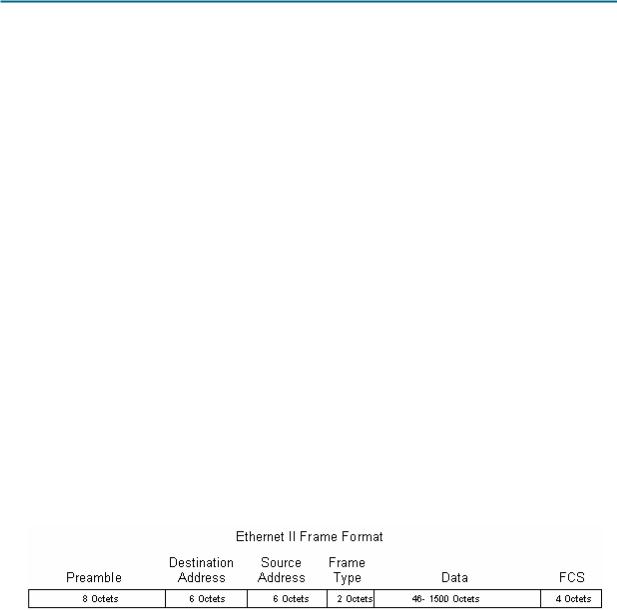
The format for an Ethernet II frame is shown in Figure 1.
Figure 1. Ethernet II Frame Format
All contents are Copyright © 1992–2007 Cisco Systems, Inc. All rights reserved. This document is Cisco Public Information. |
Page 2 of 7 |
CCNA Exploration |
|
Network Fundamentals: Data Link Layer |
Lab 7.5.2 Frame Examination |
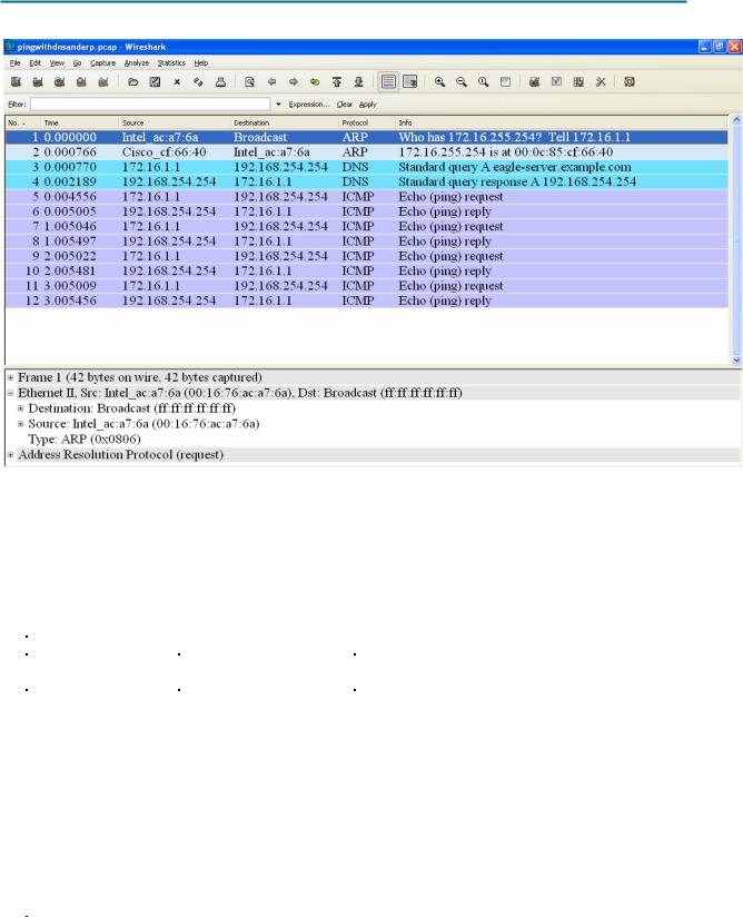
Figure 2. Wireshark Capture of the ping Command
In Figure 2, the Panel List window shows a Wireshark capture of the ping command between a pod host computer and Eagle Server. The session begins with the ARP protocol querying for the MAC address of the Gateway router, followed by a DNS query. Finally, the ping command issues echo requests.
In Figure 2, the Packet Details window shows Frame 1 detail information. Using this window, the following Ethernet II frame information can be obtained:
Field |
Value |
Description |
Preamble |
Not shown in capture. |
This field contains synchronizing bits, |
|
|
processed by the NIC hardware. |
Destination Address |
ff:ff:ff:ff:ff:ff |
Layer 2 addresses for the frame. Each |
Source Address |
00:16:76:ac:a7:6a |
address is 48 bits long, or 6 bytes, expressed |
|
|
as 12 hexadecimal digits, 0-9,A-F. |
|
|
A common format is 12:34:56:78:9A:BC. |
|
|
The first six hex numbers indicate the |
|
|
manufacturer of the network interface card |
|
|
(NIC). Refer to |
|
|
http://www.neotechcc.org/forum/macid.htm for |
|
|
a list of vendor codes. The last six hex digits, |
|
|
ac:a7:6a, are the serial number of the NIC. |
|
|
The destination address may be a broadcast |
|
|
which contains all 1s or unicast. The source |
|
|
address is always unicast. |
Frame Type |
0x0806 |
For Ethernet II frames, this field contains a |
|
|
hexadecimal value that is used to indicate the |
|
|
type of upper layer protocol in the data field. |
|
|
There are numerous upper layer protocols |
|
|
supported by Ethernet II. Two common frame |
All contents are Copyright © 1992–2007 Cisco Systems, Inc. All rights reserved. This document is Cisco Public Information. |
Page 3 of 7 |
CCNA Exploration |
|
Network Fundamentals: Data Link Layer |
Lab 7.5.2 Frame Examination |
Field |
Value |
Description |
|
|
|
types are: |
|
|
|
Value |
Description |
|
|
0x0800 |
IPv4 Protocol |
|
|
0x0806 |
Address resolution |
|
|
|
protocol (ARP) |
Data |
ARP |
Contains the encapsulated upper level |
|
|
|
protocol. The data field is between 46 – 1500 |
|
|
|
bytes. |
|
FCS |
Not shown in capture. |
Frame Check Sequence, used by the NIC to |
|
|
|
identify errors during transmission. The value |
|
|
|
is computed by the sending machine, |
|
|
|
encompassing frame addresses, type, and |
|
|
|
data field. It is verified by the receiver. |
|
What is the significance of all 1s in the destination address field?
______________________________________________________________________________
______________________________________________________________________________
From the information contained in the Packet List window for the first frame, answer the following questions about the destination and source MAC address:
Destination Address:
MAC address: ____________________
NIC manufacturer: ____________________
NIC serial number: ____________________
Source Address:
MAC address: ____________________
NIC manufacturer: ____________________
NIC serial number: ____________________
From the information contained in the Packet List window for the second frame, answer the following questions about the destination and source MAC address:
Destination Address:
MAC address: ____________________
NIC manufacturer: ____________________
NIC serial number: ____________________
Source Address:
MAC address: ____________________
NIC manufacturer: ____________________
NIC serial number: ____________________
All contents are Copyright © 1992–2007 Cisco Systems, Inc. All rights reserved. This document is Cisco Public Information. |
Page 4 of 7 |
CCNA Exploration |
|
Network Fundamentals: Data Link Layer |
Lab 7.5.2 Frame Examination |
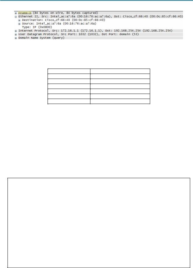
Figure 3. Frame 3 Fields
Figure 3 contains an exploded view of the Frame 3 Wireshark capture. Use the information to complete the following table:
Field |
Value |
Preamble
Destination Address
Source Address
Frame Type
Data
FCS
In the following task, Wireshark will be used to capture and analyze packets captured on the pod host computer.
Task 2: Use Wireshark to Capture and Analyze Ethernet II Frames.
Step 1: Configure Wireshark for packet captures.
Prepare Wireshark for captures. Click Capture > Interfaces, and then click the start button that corresponds to the 172.16.x.y interface IP address. This will begin the packet capture.
Step 2: Start a ping to Eagle Server and capture the session.
Open a Windows terminal window. Click Start > Run, type cmd, and click OK.
Microsoft Windows XP [Version 5.1.2600]
(C) Copyright 1985-2001 Microsoft Corp.
C:\> ping eagle-server.example.com
Pinging eagle-server.example.com [192.168.254.254] with 32 bytes of data:
Reply from 192.168.254.254: bytes=32 time<1ms TTL=62
Reply from 192.168.254.254: bytes=32 time<1ms TTL=62
Reply from 192.168.254.254: bytes=32 time<1ms TTL=62
Reply from 192.168.254.254: bytes=32 time<1ms TTL=62
Ping statistics for 192.168.254.254:
Packets: Sent = 4, Received = 4, Lost = 0 (0% loss),
Approximate round trip times in milli-seconds:
Minimum = 0ms, Maximum = 0ms, Average = 0ms
C:\>
Figure 4. Ping to eagle-server.example.com
All contents are Copyright © 1992–2007 Cisco Systems, Inc. All rights reserved. This document is Cisco Public Information. |
Page 5 of 7 |

CCNA Exploration |
|
Network Fundamentals: Data Link Layer |
Lab 7.5.2 Frame Examination |
Ping eagle-server.example.com, as shown in Figure 4. When the command has finished execution, stop Wireshark captures.
Step 3: Analyze the Wireshark capture.
The Wireshark Packet List window should start with an ARP request and reply for the MAC address of the Gateway. Next, a DNS request is made for the IP address of eagle-server.example.com. Finally, the ping command is executed. Your capture should look similar to the one shown in Figure 2.
Use your Wireshark capture of the ping command to answer the following questions:
Pod computer MAC address information:
MAC address: ____________________
NIC manufacturer: ____________________
NIC serial number: ____________________
R2-Central MAC address information:
MAC address: ____________________
NIC manufacturer: ____________________
NIC serial number: ____________________
A student from another school would like to know the MAC address for Eagle Server. What would you tell the student?
What is the Ethernet II frame type value for an ARP Request? ____________________
What is the Ethernet II frame type value for an ARP Reply? ____________________
What is the Ethernet II frame type value for a DNS query? ____________________
What is the Ethernet II frame type value for a DNS query response? ____________________
What is the Ethernet II frame type value for an ICMP echo? ____________________
What is the Ethernet II frame type value for an ICMP echo reply? ____________________
Task 3: Challenge
Use Wireshark to capture sessions from other TCP/IP protocols, such as FTP and HTTP. Analyze the captured packets, and verify that the Ethernet II frame type remains 0x0800.
Task 4: Reflection
In this lab, Ethernet II frame header information was examined. A preamble field contains seven bytes of alternating 0101 sequences, and one byte that signals the beginning of the frame, 01010110. Destination and source MAC addresses each contain 12 hex digits. The first six hex digits contain the manufacturer of the NIC, and the last six hex digits contain the NIC serial number. If the frame is a broadcast, the destination MAC address contains all 1s. A 4-byte frame type field contains a value that indicates the protocol in the data field. For IPv4, the value is 0x0800. The data field is variable and contains the encapsulated upper layer protocol. At the end of a frame, a 4-byte FCS value is used to verify that there were no errors during transmission.
All contents are Copyright © 1992–2007 Cisco Systems, Inc. All rights reserved. This document is Cisco Public Information. |
Page 6 of 7 |

CCNA Exploration |
|
Network Fundamentals: Data Link Layer |
Lab 7.5.2 Frame Examination |
Task 5: Clean Up
Wireshark was installed on the pod host computer. If Wireshark needs to be uninstalled, click Start > Control Panel. Open Add or Remove Programs. Highlight Wireshark, and click Remove.
Remove any files created on the pod host computer during the lab.
Unless directed otherwise by the instructor, turn off power to the host computers. Remove anything that was brought into the lab, and leave the room ready for the next class.
All contents are Copyright © 1992–2007 Cisco Systems, Inc. All rights reserved. This document is Cisco Public Information. |
Page 7 of 7 |