

Lab 10.6.3: Establishing a Console Session with Minicom
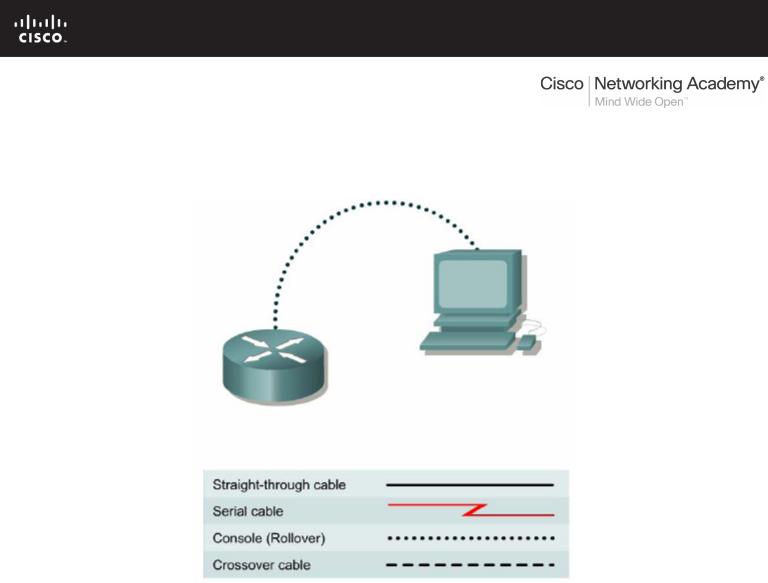
Topology Diagram
Learning Objectives
Upon completion of this lab, you will be able to:
•Connect a router and computer using a console cable.
•Configure Minicom to establish a console session with the router.
•Perform basic commands.
Background
Minicom is a text-based UNIX terminal emulation program, similar to the Windows HyperTerminal program. Minicom can be used for many purposes, such as controlling a modem or accessing a Cisco router through the serial console connection. The Linux or UNIX operating system is required.
Scenario
Set up a network similar to the one in the Topology Diagram. Any router that meets the interface requirements may be used. Possible routers include 800, 1600, 1700, 2500, 2600 routers, or a combination. The following resources will be required:
•Linux/UNIX computer with a serial interface and Minicom loaded
•Cisco router
•Console (rollover) cable for connecting the workstation to the router
All contents are Copyright © 1992–2007 Cisco Systems, Inc. All rights reserved. This document is Cisco Public Information. |
Page 1 of 4 |
CCNA Exploration |
|
Network Fundamentals: Planning and Cabling Networks |
Lab 10.6.3 Establishing a Console Session with Minicom |
Task 1: Connect a Router and Computer with a Console Cable.
Step 1: Set up basic physical connection.
Ensure that power is turned off on the computer and Cisco router. Connect the console (rollover) cable to the console port on the router. Connect the other cable end to the PC with a DB-9 or DB-25 adapter to the COM 1 port.
Step 2: Power on devices.
Enable power to the computer and router.
Task 2: Configure Minicom to Establish a Console Session with the Router.
Step 1: Start Minicom application in configuration mode.
Note: To configure Minicom, root access is required. From the Linux command prompt, start minicom with the –s option. This starts Minicom in the configuration mode:
[root]# minicom –s <ENTER>
Step 2: Configure Minicom for serial communications.
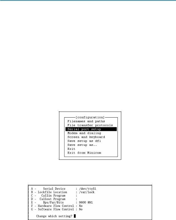
Figure 1. Main Configuration Window
Refer to Figure 1. To configure the serial port, scroll down the configuration list and select Serial port setup. Press Enter.
Figure 2. Serial Port Configuration Window
All contents are Copyright © 1992–2007 Cisco Systems, Inc. All rights reserved. This document is Cisco Public Information. |
Page 2 of 4 |

CCNA Exploration |
|
Network Fundamentals: Planning and Cabling Networks |
Lab 10.6.3 Establishing a Console Session with Minicom |
Refer to Figure 2. Use the letter by the field to change a setting. Refer to Table 1 for the correct values.
Option |
Field |
|
|
Value |
|
A |
Serial Device |
|
/dev/ttyS0 for COM1 |
|
|
|
|
|
/dev/ttyS1 for COM2 |
||
E |
Bps/Par/Bits |
|
Bps9600 |
||
|
|
|
ParNone |
||
|
|
|
Bits- 8 |
||
|
|
|
Stop bits- 1 |
||
|
|
|
(or, select option ‘Q’) |
||
F |
Hardware Flow Control |
|
Toggle- |
No |
|
G |
Software Flow Control |
|
Toggle- |
No |
|
Table 1. Serial Port Settings
Return to the Configuration menu by pressing Enter or Esc.
Figure 3. Serial Port Configuration Window
Refer to Figure 3. Select Save setup as dfl (default file). When Minicom is restarted, the default values will be reloaded.
Step 3: Close Minicom.
When finished, close the Minicom session. Select Exit from Minicom.
Step 4: Restart the Minicom session.
[root]# minicom <ENTER>
When the session window starts, press the Enter key. There should be a response from the router. This indicates that connection has been successfully completed. If there is no connection, troubleshoot as necessary. For example, verify that the router has power. Check the connection to the correct COM1 port on the PC and the console port on the router. If there is still no connection, ask the instructor for assistance.
Task 3: Perform Basic Commands.
Minicom is a text-based, menu-driven, serial communication utility. Basic commands are not intuitive. For example, users communicate with remote devices within the terminal window. However, to control the utility, use <CTRL> A. To get help, press <CTRL> A, followed by Z.
All contents are Copyright © 1992–2007 Cisco Systems, Inc. All rights reserved. This document is Cisco Public Information. |
Page 3 of 4 |
CCNA Exploration |
|
Network Fundamentals: Planning and Cabling Networks |
Lab 10.6.3 Establishing a Console Session with Minicom |
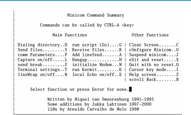
Figure 4. Minicom Command Summary Screen
Refer to Figure 4 for a list of functions and corresponding keys. To quit Minicom, press <CTRL> A, followed by either Q or X.
Task 4: Reflection
This lab provided information for establishing a console connection to a Cisco router using Minicom. Cisco switches are accessed in the same fashion.
Task 5: Clean Up
Unless directed otherwise by the instructor, turn off power to the host computer and router. Remove the rollover cable.
Remove anything that was brought into the lab, and leave the room ready for the next class.
All contents are Copyright © 1992–2007 Cisco Systems, Inc. All rights reserved. This document is Cisco Public Information. |
Page 4 of 4 |

10.7.1: Skills Integration Challenge: Network Planning and
Interface Configuration
Topology Diagram
Addressing Table
Device |
Interface |
IP Address |
Subnet Mask |
Default Gateway |
|
Fa0/0 |
|
|
N/A |
R1 |
S0/0/0 |
|
|
N/A |
|
S0/0/1 |
|
|
N/A |
|
Fa0/0 |
|
|
N/A |
R2 |
Fa0/1 |
|
|
N/A |
S0/0/0 |
|
|
N/A |
|
|
|
|
||
|
S0/0/1 |
|
|
N/A |
|
Fa0/0 |
|
|
N/A |
R3 |
S0/0/0 |
|
|
N/A |
|
S0/0/1 |
|
|
N/A |
PC-1A |
NIC |
|
|
|
PC-2A |
NIC |
|
|
|
PC-3A |
NIC |
|
|
|
Eagle_Server |
NIC |
|
|
|
All contents are Copyright © 1992–2007 Cisco Systems, Inc. All rights reserved. This document is Cisco Public Information. |
Page 1 of 3 |
CCNA Exploration |
|
Network Fundamentals: |
|
Planning and Cabling Networks |
10.7.1: Skills Integration Challenge: Network Planning and Interface Configuration |
Learning Objectives
Upon completion of this lab, you will be able to:
•Build the network topology.
•Plan the IP addresses.
•Configure router and PC interfaces.
•Test the network.
Background
Practice your network building, planning, and configuration skills. Device names and routing have already been configured.
Task 1: Build the Network Topology.
Use the following charts, and the devices in the Device Pool, to create the topology.
Routers:
Hostname |
Interface |
Connects To |
Interface |
R1 |
Fa0/0 |
SW-1 |
Fa0/1 |
R1 |
S0/0/0 (DCE) |
R2 |
S0/0/0 |
R1 |
S0/0/1 (DCE) |
R3 |
S0/0/1 |
R2 |
Fa0/0 |
SW-2A |
Fa0/1 |
R2 |
S0/0/1 (DCE) |
R3 |
S0/0/0 |
R2 |
Fa0/1 |
SW-2B |
Fa0/1 |
R3 |
Fa0/0 |
SW-3 |
Fa0/1 |
Switches: |
|
|
|
|
|
|
|
Hostname |
Interface |
Connects To |
Interface |
SW-1 |
Fa0/2 |
PC-1A |
FastEthernet |
SW-2A |
Fa0/2 |
PC-1B |
FastEthernet |
SW-2B |
Fa0/2 |
Eagle_Server |
FastEthernet |
SW-3 |
Fa0/2 |
PC-1C |
FastEthernet |
All contents are Copyright © 1992–2007 Cisco Systems, Inc. All rights reserved. This document is Cisco Public Information. |
Page 2 of 3 |

CCNA Exploration |
|
Network Fundamentals: |
|
Planning and Cabling Networks |
10.7.1: Skills Integration Challenge: Network Planning and Interface Configuration |
Task 2: Create and Assign an Addressing Scheme.
You are asked to use the 192.168.1.0 /24 address space. Seven total networks are required; assign the networks in decreasing order of number of hosts required for efficient use of address space. Use the following charts to create an effective addressing scheme:
LAN:
|
Hostname |
Interface |
Number of Hosts |
|
|
|
R1 |
Fa0/0 |
60 |
|
|
|
R2 |
Fa0/0 |
10 |
|
|
|
Fa0/1 |
30 |
|
|
|
|
|
|
|
||
|
R3 |
Fa0/0 |
7 |
|
|
|
WAN: |
|
|
|
|
|
|
|
|
||
|
Hostname |
Address to be Assigned |
Number of Hosts |
||
|
R1-R2 |
R1-First host address |
2 |
|
|
|
R1-R3 |
R1-First host address |
2 |
|
|
|
R2-R3 |
R2-First host address |
2 |
|
|
Use the following rules to assign the IP addresses.
•PCs will use the first host address in the subnet; the server will use the second to last host address in its subnet.
•All FastEthernet ports on a router will use the last host address of the assigned subnet.
•The R1-R2 link will use the first WAN subnet, the R1-R3 link will use the second WAN subnet, and the R2-R3 link will use the third WAN subnet. R1 and R2 DCE interfaces should have clock rates of 56000.
Task 3: Interface Configuration
Perform interface configuration of the R1, R2, and R3 routers, the PCs, and the server according to the addressing scheme above.
Task 4: Testing Connectivity
Make sure all PCs can ping their gateways, other PCs, and the server.
All contents are Copyright © 1992–2007 Cisco Systems, Inc. All rights reserved. This document is Cisco Public Information. |
Page 3 of 3 |