


AMBA ASB
4.3ASB transfers
When a master has been granted the bus it can perform the following transfers:
•NONSEQUENTIAL data transfer
•SEQUENTIAL data transfer
•ADDRESS-ONLY transfer.
A transfer is defined as starting at the falling edge of BCLK after the previous transfer has completed, as indicated by BWAIT being LOW, and running until the falling edge of BCLK after a complete transfer response is received, again indicated by BWAIT being LOW.
The type of transfer that a bus master will perform can be determined by the value on the BTRAN signals at the start of the transfer. During the transfer the BTRAN signals will change to indicate the type of the following transfer.
4-6 |
© Copyright ARM Limited 1999. All rights reserved. |
ARM IHI 0011A |

AMBA ASB
4.3.1Nonsequential transfer
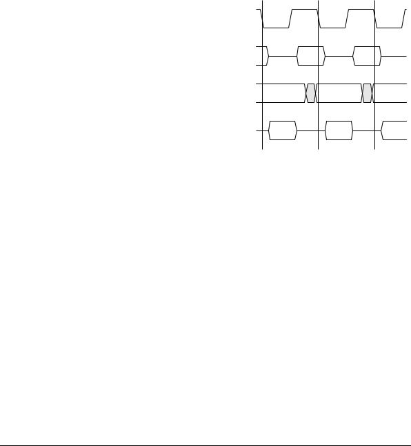
A NONSEQUENTIAL transfer occurs for either a single transfer or at the start of a burst of transfers. Figure 4-3 shows a typical NONSEQUENTIAL read transfer including wait states.
|
|
Decode cycle |
|
Read access |
|
BCLK |
|
|
|
|
|
BTRAN[1:0] |
|
N-TRAN |
|
|
|
BA[31:0] |
|
|
|
Addr |
|
BWRITE |
|
|
|
|
|
BSIZE[1:0] |
|
|
|
Control |
|
BPROT[1:0] |
|
|
|
|
|
DSELx |
|
|
|
|
|
BWAIT |
|
|
|
|
|
BERROR |
DONE |
WAIT |
WAIT |
WAIT |
DONE |
BLAST |
|
|
|
|
|
BD[31:0] |
|
|
|
|
Data |
|
|
|
|
(A+8) |
|
Read |
|
|
|
|
|
|
|
|
|
|
Start of transfer |
End of transfer |
Figure 4-3 Nonsequential transfer
The following points should be noted:
•The address and control signals start to change in the BCLK HIGH phase before the transfer starts.
•For a NONSEQUENTIAL transfer a valid address may not be available until very late in the BCLK HIGH phase, or even until the start of the clock LOW phase at the beginning of the transfer.
ARM IHI 0011A |
© Copyright ARM Limited 1999. All rights reserved. |
4-7 |

AMBA ASB
•The decoder, which requires a stable address in order to select the correct slave, will automatically insert a wait state in the first cycle of NONSEQUENTIAL transfers. This is referred to as a DECODE cycle and provides an adequate time for the decoder to examine the high order address lines and assert the appropriate DSELx during the HIGH phase of the DECODE cycle.
•For the remaining cycles of the transfer, the slave will provide a transfer response and the data exchange will occur between the master and slave.
Note
In certain system designs, which are typically those with a low-frequency system clock, the address is valid early enough in the BCLK HIGH phase before the start of the transfer, allowing the decoder to generate a valid DSELx signal before the falling edge of BCLK. Such systems do not require the addition of a DECODE cycle at the start of the NONSEQUENTIAL transfers and the operation of such a system is described in more detail in Address decode on page 4-14.
•The data bus, BD[31:0], must be valid by the falling edge of BCLK at the end of the transfer. During a write cycle, the bus master is responsible for driving the data bus, which it will do from the start of the clock HIGH phase, in order that the slave may accept valid data by the falling edge of the clock. During a read cycle the appropriate slave must drive the data bus, such that it is valid by the end of the HIGH phase.
•Because a number of different bus slaves may drive data on to the ASB it is necessary to ensure that different slaves do not overlap when driving data onto the bus. An entire phase of non-overlap is provided as slaves and masters may not drive data during the clock LOW phase at the start of a NONSEQUENTIAL transfer.
•As many of the bus signals are shared and have turnaround periods when there is no active driver, it is necessary to ensure that bus hold cells are provided to prevent floating levels being present on the bus.
4.3.2Sequential transfer
A SEQUENTIAL transfer occurs when the address is related to that of the previous transfer. The control information, as indicated by BWRITE, BPROT and BSIZE, will be the same as the previous transfer.
If the SEQUENTIAL transfer follows a NONSEQUENTIAL or another SEQUENTIAL transfer, the address can be calculated by using the previous size and address. For example a burst of word accesses would be to addresses A, A+4, A+8, whereas a burst of halfword accesses would be to addresses A, A+2, A+4.
4-8 |
© Copyright ARM Limited 1999. All rights reserved. |
ARM IHI 0011A |
AMBA ASB
If a SEQUENTIAL transfer follows an ADDRESS-ONLY cycle then the address will be the same as that of the ADDRESS-ONLY cycle. This combination of an ADDRESSONLY followed by SEQUENTIAL allows both a single access using a SEQUENTIAL transfer and also allows a burst of transfers to start with a SEQUENTIAL transfer. An example of the use of an ADDRESS-ONLY followed by SEQUENTIAL is shown later in Figure 4-6.
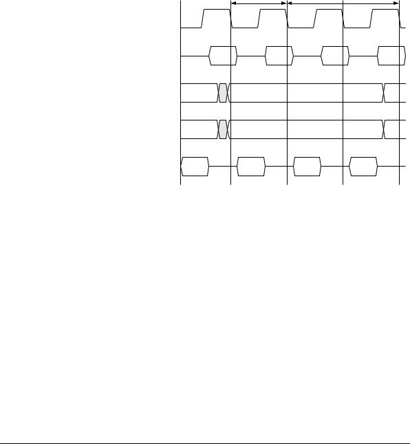
Figure 4-4 shows a SEQUENTIAL transfer with one wait state. This closely resembles a NONSEQUENTIAL transfer.
BCLK |
|
BTRAN[1:0] |
|
BA[31:0] |
|
BWRITE |
|
BSIZE[1:0] |
|
BPROT[1:0] |
|
BD[31:0] |
|
Write |
|
BD[31:0] |
|
Read |
|
BWAIT |
|
BERROR |
DONE |
BLAST |
|
Read access
S-TRAN |
|
Previous address |
|
+ transfer size |
|
Control |
|
|
Data |
|
Data |
WAIT |
DONE |
Figure 4-4 Sequential transfer
The main differences are:
•BTRAN signals indicate a SEQUENTIAL transfer
•address is always valid in the BCLK HIGH phase at the start of the transfer
•address is related to the preceding transfer
ARM IHI 0011A |
© Copyright ARM Limited 1999. All rights reserved. |
4-9 |

AMBA ASB
•control information remains the same as the preceding transfer
•for a write the data bus is driven throughout the entire transfer.
The data bus, BD[31:0], can be driven throughout the entire transfer because, unlike the NONSEQUENTIAL case, there is no requirement to provide a period of time to allow for bus turnaround.
4.3.3Address-only transfer
An ADDRESS-ONLY transfer indicates that no data transaction is required. During an ADDRESS-ONLY transfer it is possible that the address and control information may also be invalid. The only signals that must be driven to valid levels are:
•BTRAN - to indicate the type of the next transfer
•BLOK - to allow the arbitration process to continue.
As ADDRESS-ONLY transactions do not access slaves on the bus, they only require a single cycle and therefore the BWAIT signal will be LOW. This signal is driven by the bus decoder, as no slave will be selected during the ADDRESS-ONLY cycle. A bus master may perform a number of ADDRESS-ONLY transfers in succession if it does not require the bus for data transfer.
The ADDRESS-ONLY transfer can be used in three different ways:
•as a true IDLE cycle (when the bus master does not require the bus)
•to speculatively broadcast an address for the next transfer, without committing to the transfer
•to provide a turnaround cycle during bus master handover.
4-10 |
© Copyright ARM Limited 1999. All rights reserved. |
ARM IHI 0011A |
AMBA ASB
If the ADDRESS-ONLY transfer is used as a true IDLE cycle then the address and control signals are not required to be valid at any point during the transfer (see Figure 4-5).
BCLK |
|
|
|
BTRAN[1:0] |
|
A-TRAN |
|
BLOK |
|
|
|
|
|
Decoder drives |
|
|
|
response |
|
BWAIT |
|
|
|
BERROR |
DONE |
DONE |
|
BLAST |
|
|
|
|
|
Start of transfer |
End of transfer |
Figure 4-5 Address-only transfer
The BLOK signal is the only exception and this must be driven to a valid level during all ADDRESS-ONLY transfers to allow the arbitration process to continue.
ARM IHI 0011A |
© Copyright ARM Limited 1999. All rights reserved. |
4-11 |
AMBA ASB
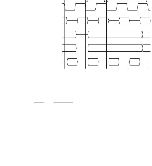
The second use of the ADDRESS-ONLY transfer is to speculatively broadcast the address for a transfer, without actually committing to the transfer (see Figure 4-6).
Address given during |
Burst starts with |
Address-only transfer |
Sequential transfer |
BCLK |
|
|
|
BTRAN[1:0] |
A-TRAN |
S-TRAN |
|
BA[31:0] |
|
Address |
|
BWRITE |
|
|
|
BSIZE[1:0] |
|
Control |
|
BPROT[1:0] |
|
|
|
BWAIT |
|
|
|
BERROR |
DONE |
WAIT |
DONE |
BLAST |
|
|
|
Figure 4-6 Address-only transfer to start burst
Using an ADDRESS-ONLY transfer to speculatively broadcast the address allows address decoding to be performed by the decoder during the ADDRESS-ONLY cycle. If the bus master then commits to the burst it is possible to start the burst with a SEQUENTIAL transfer, thus removing the need for an extra DECODE cycle before the transfer starts.
4-12 |
© Copyright ARM Limited 1999. All rights reserved. |
ARM IHI 0011A |
AMBA ASB
The final use of an ADDRESS-ONLY transfer is to provide a turnaround period during bus master handover (see Figure 4-7).
Address-only transfer |
First transfer of |
for bus handover |
new bus master |
BCLK |
|
|
|
|
BTRAN[1:0] |
|
A-TRAN |
S-TRAN |
|
BA[31:0] |
|
|
Address |
|
BLOK |
|
|
|
|
BWRITE |
|
|
Control |
|
BSIZE[1:0] |
|
|
|
|
|
|
|
|
|
BPROT[1:0] |
|
|
|
|
BWAIT |
|
|
|
|
BERROR |
DONE |
DONE |
WAIT |
DONE |
BLAST |
|
|
|
|
Figure 4-7 Address-only transfer for bus master handover
A bus master which becomes granted on the bus must start with an ADDRESS-ONLY transfer and, in this case, the new bus master does not drive the address and control signals immediately, but provides a phase of turnaround before driving the signals in the LOW phase of the transfer.
Note
In this case, the address and control information will not become valid until the LOW phase of BCLK.
ARM IHI 0011A |
© Copyright ARM Limited 1999. All rights reserved. |
4-13 |