


10
Deactivation by Coking
Octavio Novaro and Cheng-Lie Li
National University of Mexico
Mexico City, Mexico
Jin-An Wang
National Polytechnic Institute
Mexico City, Mexico
1INTRODUCTION
Catalytic naphtha reforming processes are accompanied by side reactions leading to carbonaceous deposits both on metallic sites and on the support of the catalyst, causing catalyst deactivation. The carbonaceous deposits on catalysts generally can be divided into different groups: (1) a constant amount of residual carbon;
(2) reversible carbon formed instantaneously during operation at working
conditions; and (3) irreversibly adsorbed carbon accumulating during reaction after several hours and eventually forming graphitic-like structures.[1,2] Some of
the carbon deposits may be beneficial, whereas most of these materials are harmful, depending on the reactions and catalysts.[3] Under working conditions, there exist several different surface compositions and structures on a Pt/Al2O3- reforming catalyst: predominantly uncovered ensembles of clean Pt sites, twodimensional overlayer carbonaceous deposits, and three-dimensional carbon islands.[4a] The presence of coke with different natures, compositions, and structures significantly influences the catalyst activity and frequently alters selectivity and, finally, lifetime. Fortunately, deactivation by coking is usually reversible and the coked catalyst can be refreshed by employing a controlled coke burnoff operation. Thus, the activity and selectivity may be completely or partially restored.
Current affiliation: East China University of Science and Technology, Shanghai, China
391
392 |
Novaro et al. |
Coking processes are complex. They are affected by various factors, including (1) the active metals (metal content, crystallite size, and dispersion); (2) catalyst support (textural properties and acidity); (3) additional promoters (Sn, Re, Ir, Ge, Cl, S); (4) operation conditions (reaction temperature, pressure, H2/oil ratio, and time on stream) and (5) feedstock properties (molecular weight and structure, hydrocarbon basicity). Clarification of these influences on coke formation is necessary to illuminate coking mechanisms and to facilitate choice of regeneration parameters and optimization of operations. Some important remarks on coke formation are found in the literature.[4b]
In the present chapter, coke locations on the surface of the catalyst and coke distribution across the catalyst pellets and along the catalyst bed are presented. Coke characterization techniques and the influencing factors for coke formation are summarized. Coking mechanisms and kinetics are also discussed. Finally, the effects of coke deposition on the activity and selectivity of the different reactions occurring in the catalytic naphtha reforming process are shown.
2COKE CHARACTERIZATION TECHNIQUES
One of the major difficulties in the study of deactivation by coking during the reforming process is the limitation in determining the composition and nature of the carbonaceous deposits. The coke usually contains complex mixtures of carbonaceous compounds and unconverted reactants or products. They cannot be related to any single chemical structure, and in most cases it is difficult to analyze their distribution. For overcoming these problems, advanced instrumental techniques are highly necessary. Among those, temperature-programmed oxidation (TPO), 13C NMR, 1H NMR, Fourier transform infrared spectroscopy (FTIR), Raman spectroscopy, X-ray diffraction (XRD), and transmission electron microscopy (TEM) are valuable in the analysis of coke amount, type, composition and structure. Additional descriptive information on some of these techniques can be found in other sources,[4b,4c] and in the chapter on characterization.
2.1Temperature-Programmed Oxidation
The TPO peak assignments, such as peak temperature and integrated peak area in the exit CO2 profile, have been widely used to study coke types, location, and combustion behavior. Generally the TPO spectrum is well resolved and consists of lowand high-temperature peaks. The former corresponds to oxidation of the coke formed on the metal function and the other is due to combustion of the coke formed on the acid sites on the support. Figure 1 is a set of TPO profiles of a series of coked bimetallic catalysts.[5]
When coke content is lower than 0.1 wt %, it is difficult to characterize it by a routine TPO technique. However, Querini and Fung[6a] used a modified TPO

Deactivation by Coking |
393 |
Figure 1 A set of TPO spectra of a series of coked reforming catalysts with various Pt loading. (From Ref.[5].)
method to identify coke type and burnoff behavior by feeding the exit gaseous mixture of coke combustion into a methanator where the Ru catalyst was used to catalyze the conversion of CO2 to CH4. This greatly enhanced the sensitivity and stability of the baseline and the resolution of the conventional TPO technique, making it possible to quantify the coke content as low as 0.01 wt %.
Because the coke particle size and morphology show a great influence on TPO profile, by a proper design of TPO experiment in combination with a kinetic model, some information concerning the coke morphology and particles can also be obtained. It was found that the coke deposits with a three-dimensional structure exhibit a coke reaction order increasing from almost 0 to approaching 1 as the oxidation reaction proceeds. By using a linear combination of power law kinetic expressions, coke concentration and coke particle size and number are roughly determined in terms of the TPO behavior.[6b]
2.2Infrared Spectroscopy
IR has been used to characterize the coke structure and compositions.[7 – 10] A typical FTIR spectrum of the coke formed on an industrial reforming catalyst

394 Novaro et al.
(Pt-Sn/Al2O3) is shown in Figure 2.[10] Two absorption bands at 744 and 871 cm21 together with two other little bands in the range of 700–900 cm21 were observed. These bands were produced by polycyclic aromatics like pyrene or chrysene. The spectrum has two sharp bands at 2846 and 2912 cm21, which are produced by the symmetrical and asymmetrical flexion vibration of the C22H bonds associated with the CH2 groups connected to the aromatic rings or aliphatic groups. In addition, the band of olefinic flexion vibration was observed at 1606 cm21, and that for C22H twisting and wagging vibration appeared at 1381, 1374, and 1460 cm21, respectively.
By studying the interaction between the adsorbed CO and the coke or coked
metal, it is possible to use the CO-FTIR technique to study coking behaviors of the catalysts. Yao and Shelef[11] studied the Re/Al2O3 catalyst by using IR of CO
adsorption, and two kinds of rhenium crystals with different coking abilities were observed: one with two-dimensional arrays spread over the alumina surface might be less readily coked but responsive to reaction with CO, giving rhenium multicarbonyl complexes bonded to Al3þ ions in the alumina surface; and
Figure 2 A typical FTIR spectrum of the coke formed on an industrial Pt-Sn/Al2O3 reforming catalyst. (From Ref.[10].)
Deactivation by Coking |
395 |
another with three dimensions, which would be most likely to form linearly adsorbed CO band, which was heavily coked. Anderson et al.[12] reported the IR results of CO adsorption on Pt, Re, and Pt-Re/Al2O3 catalysts before and after coking. About 92% of the CO adsorption was inhibited by coking after 2 min of CO adsorption on coked Pt/Al2O3 compared to the uncoked catalyst. However, on the coked Re/Al2O3, the intensity of CO adsorption band was 52% of that shown in the uncoked sample, indicating that 42% of Re0 sites for the linear adsorption of CO had been poisoned by coking. When CO adsorbed on the coked Pt-Re/Al2O3, the intensity of the dominant IR band was reduced by 87%, which is slightly lower than that for Pt alone but bigger than that for Re alone. They also found that small patches of uncoked Pt were enlarged after addition of CO due to the mobility of the carbonaceous layer induced by CO adsorption.
2.3 13C NMR and 1H NMR
13C NMR and 1H NMR techniques are useful for coke characterization because they do not require the separation of the coke deposits from the catalysts. The fairly wide range of chemical shift of the 13C nucleus makes it easy to distinguish among different compounds present in the coked catalysts. Moreover, it is also possible using this technique to obtain information such as mobility of the coke and related host–guest interaction.[13]
Carbon atoms with an sp2 hybridized state usually present a chemical shift between 82 and 160 ppm, whereas those with an sp3 hybridized state have a shift between 0 and 82 ppm in the NMR spectrum. Figure 3 shows that the NMR spectrum of coke deposited on an industrial reforming Pt-Sn/g-Al2O3 catalyst consists of one large absorption peak at around 125 ppm, showing that the coke contains components having polynuclear aromatic and graphite-like structures with an sp2 hybridized state and negligible amounts of 22CH3 side chains with an sp3 hybridized state.[10] Moreover, by using 1H NMR, different hydrogens (Ha, Hb, and Hg) in saturated groups linked in the condensed aromatic rings in the extracted coke are identified.[14 – 16]
2.4Raman Spectroscopy
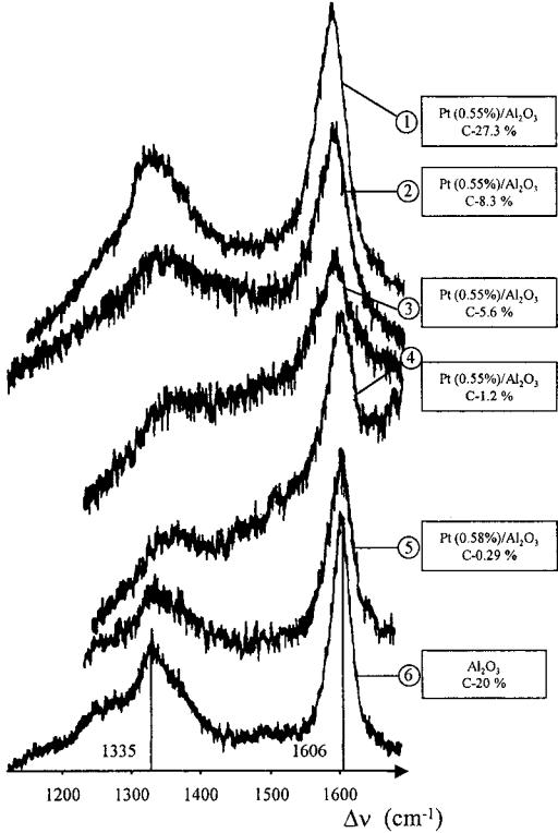
It is well known that in the beginning stage of the reforming process, with a coke amount less than 1 wt %, most of the coke is formed on the metals and some deposits on acid sites in high dispersion with poor crystallization. In this case, it is difficult to apply XRD for coke structure study. However, the laser Raman spectroscopic technique is powerful for coke characterization in the cases of low coke content and graphitization of amorphous coke due to its high sensitivity. It is not necessary to separate the coke from the coked catalysts. Well-crystallized
396 |
Novaro et al. |
Figure 3 An NMR spectrum of coke deposited on an industrial Pt-Sn/gAl2O3 reforming catalyst. (From Ref.[10].)
graphite usually presents only two Raman-active fundamental modes: one is an interlayer mode at about 42 cm21 and another is an intralayer mode at around 1581 cm21. Pregraphitic carbons show another broad composite band with a maximum at about 1355 cm21. The ratio I1355/I1581 has been correlated to the size of graphite crystallites or, more precisely, to the average diameter of the aromatic layer.[17,18]
Espinat et al.[19] reported an interesting work concerning the coke formed on both monoand bimetallic reforming catalysts by laser Raman spectroscopic technique. The coke is shown in a wide range between 0.29 and 27.3 wt % to exhibit a highly aromatic nature and very likely consists of a two-dimensional carbon structure. The alteration of the spectra with the feed composition, H2/oil ratio, and second metal addition clearly reflects the changes in structure, composition, and average crystallite sizes of the coke (Fig. 4).
Deactivation by Coking |
397 |
Figure 4 A set of Raman spectra for different coked catalysts. (From Ref.[19].)
398 |
Novaro et al. |
2.5X-ray Diffraction
XRD is usually used to determine the coke structure and crystal size.[20,21] It was shown that a coked Pt/Al2O3 catalyst consists of a pseudographitic phase with
˚
large crystals about 250 A and of an amorphous phase located on small clusters of
˚ ˚ ˚
size from 10 A to 15 A. The coke structure shows a spacing of 3.4 A between the planes, which is greater than the spacing between graphite layers, indicating that the forces operating between basal planes are far weaker than the bonds within
the planes of carbon where the C22C distance are all equal. This is mostly due to the presence of five-carbon atom rings or alkyl chains joined to the rings.[22]
2.6Transmission Electronic Microscopy
Cabrol and Oberlin,[23] using TEM as a tool for coke characterization, determined two locations of the carbonaceous materials on a spent Pt/alumina catalyst that had been treated under a typical industrial reforming condition. The carbonaceous deposits consisted of small stacks of two or three aromatic planar structures of
˚
fewer than 12 rings with a size smaller than 10 A, which are formed parallel to the alumina crystal faces, and then an increasing quantity of such carbon units gathered to form shells with porous carbon particles in a random fashion over the entire catalyst. Pt is assumed to play an important role in the creation of intermediates for coke formation, so that the small basic structure units of coke are formed in the interface.
Gallezot and coworkers[24] studied the location and structure of carbonaceous deposits formed during the coking of Pt/Al2O3 catalyst in the presence of cyclopentane at 4408C by TEM. They found that patches of amorphous carbon covered the support surrounding each metal particle and the coke coverage extended as far as 20 nm from the given particles. The local structure of the coke was neither graphitic nor pregraphitic, but a disordered mixture of polyaromatic molecules, which was sometimes limited by the edges of the alumina sheets where the metal particles were located. However, the coke frequently spilled onto neighboring alumina sheets.
By using electron microscopy, the interaction between the metal and support and the coke on the reforming catalyst can be investigated. Chang and coworkers[25] found that although a used commercial catalyst contained large amounts of coke (7–12%) with a characteristic of short-range crystallographic order, metal particles were still observed, indicating that some of the metal particles were relatively free of carbonaceous deposits. In situ TEM studies performed on a model Pt-supported catalyst system showed that upon reaction in a hydrocarbon environment, the metal particles were capable of hydrogasifying carbon in their immediate vicinity. During this process the particles underwent a wetting and spreading action at the deposit interface in a narrow temperature
Deactivation by Coking |
399 |
range between 4808C and 6008C, which was believed to be a key factor in the maintenance of the small metal particle size during the reforming reactions.[25]
3LOCALIZATION AND DISTRIBUTION OF COKE
3.1Locations and Distribution of the Coke on the Catalyst Surface
Coke may deposit on different locations on the catalyst. As shown in Figure 1, two different types of coke with different combustion behaviors formed on different locations are identified: one burned off at low temperature range (200–
4008C) and another at high temperature range (400–5508C), which individually corresponds to the coke produced on the metal and acidic support.[5,26]
On the metal crystals with various coordinations, coke formation is also different. Arteaga and coworkers[27] used CO as probe to monitor the effect of Pt site character on the coke formation on Pt/Al2O3 and Pt-Sn/Al2O3 catalysts that were coked by heat treatment in heptane/hydrogen. Four types of Pt sites with different coordinations on Pt/Al2O3 were distinguished: (1) the lowest coordination Pt atoms [n(CO) , 2030 cm21] were free from coke, confirming that these sites, which are at corner or apex atoms on the small Pt particles, were more resistant to coking than the other types of Pt site present; (2) the highest coordination sites in large ensemble of Pt atoms [n(CO) ¼ 2080 cm21] whose exposed low-index planes in Pt/Al2O3 were heavily poisoned by coke; (3) the intermediate coordination sites [n(CO) ¼ 2030–2060 cm21] that are possibly at edges or steps of Pt particles were also heavily coked; and (4) the sites in smaller two-dimensional ensembles of Pt atoms exhibiting a bridging bond with CO
(2060–2065 cm21) were partially poisoned by coke.
Espinat et al.[21] observed three zones on a coked catalyst. In the coke-free zone, the sample was identical in all aspects to the fresh catalyst. In the slightly coked zone, a layer of pregraphitic carbon with a thickness of a few atoms was observed. This kind of coke is generally poorly organized. In the highly coked zones, the support is buried in the three-dimensional coke with several hundred angstroms of thickness. These observations confirm that the carbonaceous deposits are greatly heterogeneous. In the case of low coke content, the carbon units gather into the pores of the catalyst and uniformly cover the individual catalyst surface to form a monoor multilayer of carbon shell. When the coke content is too high, it blocks the mouth of the channel or pores of the catalyst.
3.2Coke Distribution Across the Catalyst Pellet
Coke is not only formed on the surface of the catalyst but also distributes inside the catalyst pellets. In most cases, the distribution of the coke across the catalyst

400 |
Novaro et al. |
particles is nonuniform. By using electron microprobe and ion microprobe techniques, the carbon distribution from surface to subsurface or inner layer of the catalyst can be determined. On a 0.67%Pt–1.47%Cl/Al2O3 catalyst, two different regions across a coked catalyst pellet were roughly distinguished (Fig. 5): in zone A, which is in the range of 10–100 mm in catalyst radii, the coke signal is very high, showing that coke concentration reaches the maximum; in zone B, which is in the range of 150–250 mm, some regions of higher carbon concentration are observed, and others are quite free from coke.[21]
3.3Coke Distribution Along the Catalyst Bed
Coke buildup along the catalyst bed is mainly determined by coking mechanisms and reaction conditions. Although changes of reaction conditions along the catalyst bed, such as hydrogen partial pressure, temperature, and concentration of each component, usually lead to difficulties in prediction of coke profile, analyses of relationship between the coke profile and influencing variables can provide
Figure 5 Coke distribution across a catalyst pellet. (From Ref.[21].)
Deactivation by Coking |
401 |
valuable information concerning the coking mechanism and its effects on the catalytic behaviors. Generally, a series mechanism produces an increasing amount of coke throughout the bed, whereas a parallel mechanism usually yields a decreasing coke profile. In more complicated reaction networks, coke deposits may result from a combination of pathways. If the main source of coke deposits is an intermediate compound, the coke profile exhibits a maximum, whereas in a
consecutive system A ! B ! C, if coke is produced from both A and C, there might be a minimum in the coke along the bed.[28a – c,29]
Querini and Fung[29a] studied the coke profile formed along the catalyst bed during n-heptane reforming on both nonsulfided and sulfided Pt and Pt-Re/Al2O3 catalysts in a fixed-bed multioutlet reactor under different conditions. They found that the coke profiles strongly depended on the reaction conditions, sulfidation, and catalyst types. The distribution of coke concentration influenced the toluene concentration profile through the catalyst bed. At low pressure (105 kPa), the coke content on the nonsulfided Pt catalyst increases in the catalyst bed from top to bottom; however, at higher pressure (1225 kPa), coke content decreases from inlet to outlet. In a moderate pressure between 105 and 1225 kPa, a maximum in the coke profile is observed near the top one-fourth of the catalyst bed. When Re was added to the Pt catalyst, the maximum of coke profile shifted from the bed bottom to upper section. On the other hand, on the sulfided catalysts, it was found that the effect of sulfur on the coke distribution is opposite to that of Re. Addition of Re to Pt/Al2O3 moves the maximum in coke toward the top of the bed;
however, addition of sulfur to Pt-Re moves this maximum in the other direction in the catalyst bed.[29b] As shown in Table 1, at the same temperature and pres-
sure, the coke content linearly increases with time on stream in the section of the catalyst bed. At the same reaction condition, the coke content decreases along the catalyst bed from top to bottom.
Coke profile in the catalyst bed is related to the gas-phase composition contacted with catalyst bed. In the upper section of the catalyst bed, the catalysts are exposed mainly to the highest concentration of reforming feed and lowest product fraction. As these fractions change along the bed, this results in a nonuniform coke distribution along the reactor. Since sulfur is slowly stripped from the sulfided catalysts, there is also a sulfur concentration profile that
increases along the bed, which leads to a shift toward the bottom of the reactor in the maximum of the coke profile.[29b]
It is noteworthy that coke is formed not only on the catalyst particles but also on the wall surfaces of the reactor. It was found by TEM, TPO, and XRD that this kind of coke is rather different from the one separated from the catalyst surface. This coke is formed from filament-like carbons. At the front end metal particles containing Fe, Cr and Ni have been detected, and Fe is present in large amount.[15] The coke formed on the inner surface of the reactor was catalyzed by the metal reactor itself, which was difficult to remove in a normal regeneration

402 |
Novaro et al. |
Table 1 Coke Content as a Function of Time On Stream in Various Sections of the Catalyst Bed
|
|
|
|
Coke (%) |
|
|
Temp. |
Pressure |
Time |
|
|
|
|
|
|
|
|
|||
(K) |
(kPa) |
(h) |
Bed 1.9 |
Bed 22.1 |
Bed 55.1 |
Bed 84.9 |
|
|
|
|
|
|
|
772 |
525 |
2 |
0.31 |
0.34 |
0.33 |
0.30 |
772 |
525 |
24 |
0.99 |
0.95 |
0.69 |
0.58 |
772 |
525 |
34 |
1.19 |
1.08 |
0.83 |
0.68 |
772 |
525 |
72 |
2.35 |
2.18 |
1.21 |
0.84 |
772 |
525 |
91 |
2.43 |
1.92 |
1.09 |
0.97 |
772 |
525 |
120 |
2.87 |
2.57 |
1.53 |
1.10 |
772 |
525 |
213 |
4.16 |
2.81 |
1.44 |
1.12 |
755 |
525 |
330 |
2.06 |
1.48 |
1.18 |
1.05 |
755 |
525 |
240 |
2.07 |
1.66 |
1.32 |
1.10 |
755 |
1225 |
24 |
0.57 |
0.54 |
0.46 |
0.40 |
755 |
1225 |
123 |
1.03 |
0.74 |
0.54 |
0.42 |
Source: Ref.[29b].
condition. To avoid this kind of coke formation, the wall surfaces of the reactor may require special pretreatment, depending on the nature of the operation.
4EFFECTS OF CATALYSTS AND OPERATING PARAMETERS ON COKING
4.1Metallic Platinum Content, Dispersion, and Ensemble Size
Metallic platinum content affects both the amount and nature of coke. Increasing platinum content usually results in an increase in the amount of coke on the catalyst, given the same or similar metal dispersion.[30 – 32] This is because the metallic function is primarily responsible for the production of the coke precursor species like methylcyclopentadiene.[33]
Coke deposition on metals is a metal structure–sensitive reaction. Some studies have reported that the catalysts with low metal dispersions are more
sensitive to autodeactivation by coke deposition than well-dispersed catalysts.[34,35] This is possible as coke formation is preferential on planes rather than
on corners and edges of the metallic crystallites.[36 – 38] From the electronic effect perspective, highly dispersed metals with small crystallites on a support usually show an electron-deficient nature due to the metal–support interaction. When the
Deactivation by Coking |
403 |
size of the metallic crystallites decreases, electrons transfer from metal to support causes an electron-deficient character to appear on the metal. This is less
favorable to the adsorption of coke precursors like cyclopentadiene, thus producing less coke during the reaction.[34,39,40] Therefore, the small crystallites
have greater coke resistance. Coke formation usually requires multiple bonded species, thus requiring high coordination number metal atoms and large ensembles. The most active sites for coking are the face atoms of the metallic crystallites, although corner atoms are also partially covered by coke.[41 – 45]
Coke formed on the metallic sites can be divided into two types: reversible
coke (H/C atomic ratio of 1.5–2.0) and irreversible coke (H/C atomic ratio of about 0.2).[46,47] The reversible coke is more easily removed by hydrogen
treatment, whereas the irreversible coke is more graphitic and is much harder to remove with hydrogen. The removal rate by hydrogen for the reversible coke is at least 1000 times higher than that of the irreversible coke.
4.2Metallic Additives
It has been proven that the addition of a second metal promoter, such as Sn, Re, Ir, In, Ge, and others, improves Pt catalyst stability and enhances the selectivity for the formation of high-octane products.[48a – f ] Beltramini and Trimm[48f ] found that carbon formation on Pt, Pt-Sn, Pt-Ir, Pt-Re, and Pt-Ge supported alumina catalysts increased with time on stream; however, the carbon amount varied with different catalysts during n-heptane reforming. In the first 2 h, carbon deposition increased in the order Pt-Sn , Pt-Re , Pt-Ge , Pt-Ir , Pt (Fig. 6). Figure 6 shows that bimetallic catalysts present increased ability to resist coking. In a recent work, the deactivation rate for n-hexane conversion caused by both sulfur
and coke deposition was found to increase in the order Pt-Ge , Pt Pt-Sn Pt-Sn.[49] Table 2 shows the effect of Re and Ir addition on the coke formation and nature.[36]
Burch and Mitchell[50] summarized the various viewpoints presented by different groups regarding the origin of these improvements related to the second
metal: (1) the formation of an alloy like Pt-Sn, and Pt-Re, which exhibit different properties either as a result of ensemble or of electron modifications;[51,52]
(2) stabilization against sintering;[53] (3) interaction with metal ions of the second element stabilized in the surface of the support;[54,55] (4) increasing hydro-
genolysis activity;[56] (5) decreasing the hydrogenolysis activity;[57] (6) suppression of surface carbiding;[58] (7) improving hydrogenation activity;[59] and (8) hydrogenation of coke residues.[60] These conclusions are all directly or indirectly related to coking or decoking processes. The following section mainly focuses on the effects of tin and rhenium additives on coke formation and the interaction between the additives and platinum.

404 |
Novaro et al. |
Figure 6 Effects of the second metal additives on the coke formation. (From Ref.[48f].)
Tin Addition
Pt-Sn system is particularly resistant to coke deactivation. The formation of coke precursors is inhibited over Pt-Sn catalyst in n-C6 reforming because the sites display low activity for the transformation of methylcyclopentene (MCPe), which is the key intermediate for producing coke via consecutive condensation reactions, to methylcyclopentadiene (MCPde), and to further MCPde dehydrogenation. This is consistent with the results obtained by Beltramini and Trimm
Table 2 Effect of Re and Ir Addition on Coke Formation and Nature
|
|
|
|
Products in |
|
|
|
|
extractable |
|
Carbon |
Graphitic |
Extractable |
coke (%) |
Catalyst |
(%) |
coke (%) |
coke (%) |
(mol wt , 202) |
|
|
|
|
|
Pt/Al2O3 |
1.18 |
72 |
28 |
30 |
Pt-Re/Al2O3 |
0.85 |
78 |
22 |
35 |
Pt-Ir/Al2O3 |
0.92 |
75 |
25 |
48 |
|
|
|
|
|
Source: Ref.[36].
Deactivation by Coking |
405 |
who postulated that the ability to decrease coke formation results from enhanced gasification of coke precursors by tin.[48f,61]
The coke coverage on tin-doped platinum catalyst is distinctly less than on
the monometallic one, although in some cases the total amount of coke is almost the same on both catalysts.[61,62] It is assumed that coke precursors are less
strongly adsorbed on the tin-doped platinum sample due to an ensemble effect of tin. Consequently, these coke precursors are more mobile and can more easily migrate to the alumina where they are finally deposited as coke. This “drain-off ” effect guarantees that a larger portion of active Pt sites remain free from blocking coke precursors and provide higher activity for the bimetallic samples.
The addition of Sn can also block the lowest coordination Pt sites and destroy large ensembles of Pt by a geometrical dilution effect. Vo¨lter and
¨ [63]
Kurschner reported that the addition of tin strongly modifies the Pt catalyst
by forming a Pt-Sn alloy that causes inhibition of hydrogenolysis due to a geometrical effect and retards the deactivation of the catalyst by modifying the coke deposition. The addition of tin did not diminish the amount of coke but increased the ability of Pt-Sn sites to resist coke poisoning by reducing adsorption of coke precursors.
Rhenium Addition
When rhenium is added to platinum, the catalytic stability is significantly improved, extending the operating period of the unit between regenerations. This
can be explained by several effects of rhenium: stabilization of the metallic phase on the support and higher resistance to deactivation by coke deposition.[64,65]
Addition of Re may divide the large platinum ensembles into smaller ones, achieving a high metal dispersion and thus inhibiting the coking reaction.[66 – 69]
Addition of Re could also destroy coke precursors by hydrogenolysis, reducing coke formation.[70] This differs from the conclusion stated by Parera et al. that the
role of Re is to decrease the dehydrogenation capacities of Pt, and therefore Re addition decreases the coke formation.[71] Table 2 shows that addition of Re not only induces a decrease in the amount of coke deposit by a transformation of the coke precursors into other species, but also induces a modification of the coke
nature, leading to more dehydrogenated coke formation and increasing the coke toxicity.[36,72]
Interaction Between Platinum and Additives
Interaction between platinum and the second metal additive produces important influences on both coke formation and its toxicity. The greater the Pt-Re interaction is, the lower the deactivation by coking on the metallic function.[73] During cyclopentane reforming on a nonsulfided Pt-Re/Al2O3 catalyst, the coke
406 |
Novaro et al. |
deposition for the metallic function and its toxicity decreases when the Pt-Re interaction increases. However, after sulfiding, the deactivation by coking depends on both the Pt-Re interaction and the working pressure. Under normal pressure, the toxicity of the formed coke increases with the degree of the Pt-Re interaction. However, at higher pressure (15 bar) the same catalyst shows less sensitivity to coke deposition.[74]
The interaction between metallic Pt and Re provides activated hydrogen that could migrate and hydrogenate coke precursors on the acidic sites.[75] Also, a strong Pt-Re interaction may inhibit the reverse spillover of hydrogen which was proposed for the elimination of hydrogen from coke precursors adsorbed on the acidic function.[76]
4.3Catalyst Support
Most of the coke is formed on the acid function of the support. When the acidity of the support decreases in the sequence Al2O3 . TiO2 . SiO2 . MgO, for
example, the amount of coke formed on these catalysts shows a similar decreasing sequence from Al2O3 to MgO.[76] When the alumina support is modified
by other promoters, such as chloride,[77 – 79] phosphorus,[80] boric acid,[81] or potassium hydroxide,[82] its acidity is enhanced or reduced, resulting in changes in the amount and types of coke produced.
Aranda and coworkers,[83] investigating coking on a supported Pt-niobia catalyst, found that more hydrogenated and lighter coke was formed on the Pt/ Nb2O5 catalyst than on the Pt/Al2O3 due to the reduced density of acidic sites on the former. Table 3 shows the amount of coke and its type for three different Pt-
supported catalysts. In addition, effects of support modified by rare earth oxides, such as CeO2, were also studied.[84,85]
Acidic zeolites with 12 ring pores, such as ZSM-3, ZSM-20, b-zeolite, Y- zeolite, and USY, have also been used as catalyst supports for reforming reactions.[86 – 90] Recently, platinum-supported basic KL or Ba2þ-doped KL
Table 3 Data Relative to the Amount of Coke on Different Catalysts
|
|
% wt/wt |
|
|
|
|
|
|
|
|
Pt-Sn/ |
Type of coke |
Pt/Nb2O5 |
Pt/Al2O3 |
Nb2O5 |
|
|
|
|
Total coke |
3.7 |
3.1 |
1.2 |
Insoluble |
1.9 |
2.2 |
— |
Soluble |
1.8 |
0.9 |
— |
Source: Ref.[83].
Deactivation by Coking |
407 |
zeolites have been considered as reforming catalysts.[91 – 95] In comparison with the acidic zeolites, zeolite L provides the highest final activity during reforming of a paraffinic industrial feedstock, indicating that coke is formed preferentially
over the acidic sites rather than over the platinum clusters. The reforming activity decreases as Pt/L . Pt/b . Pt/USY.[96] It was observed that after reaction the
Pt/BaKL showed a gray color while the Pt/b and Pt/USY zeolite were black. Under identical conditions, the deactivation rate of USY was higher than b- zeolite due to its more numerous acidic sites.[96] The generation of bulky coke deposits in the supercages of the USY zeolite results in the blocking of its pore, thus preventing the access of the reactants to any internal active sites.
4.4Operating Conditions
The effect of operating conditions on the performance of reforming catalysts has been discussed in Chapter 2 of this book. Enhancement of gasoline octane number or BTX aromatics concentration in reformates is conveniently achieved in a commercial reforming unit under more severe operating conditions by lowering space velocity (expressed as LHSV) or raising reactor inlet temperature (WAIT) at constant pressures. Experience from commercial reforming units indicates that doubling LHSV requires a WAIT increase of 108C to keep reformate research octane number (RONC) unchanged in the range of 90– 100.[97] Changes in operating parameters also exert an important influence on catalyst coking behaviors. High severity would produce a decrease in reformate yield because of undesired hydrocracking as well as hydrogenolysis reactions. Coke formation is also accelerated and it grows preferably on the support. The coke is more dehydrogenated and graphitic at higher temperatures and lower
LHSV under constant pressure and hydrogen-to-oil ratio. The same trend has been observed in increasing time on stream.[98 – 100]
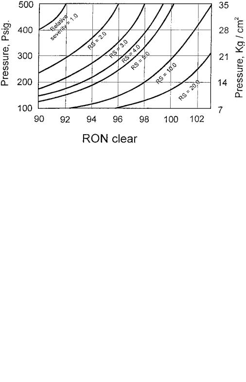
A reduction in pressure is one other way to increase severity in reforming reactions. In Figure 7, it is shown that doubling of relative severity (RS) from 2 to 4 would boost the reformate RONC from 92.2 to 96.5. Of course, higher severity concomitantly increases catalyst coking rate, shortening the cycle life from 12 months to 6 months. Likewise, at a RONC of 96.2 reducing pressure from 300 to 160 psig will double RS and thus also produce a lowering of the cycle life by half because of deactivation by coke deposition on the catalyst. Contrary to the impact of reaction temperature, Figure 8 shows that a reduction in pressure, which also increases RS, offers benefits of an increase in both reformate and hydrogen yields because it may increase the rate of dehydrogenation and dehydrocyclization
while concomitantly decreasing hydrocracking reactions. In addition, it has been demonstrated[36,101,102] that coke is deposited predominantly on the support
under increasing pressures that only can be burned off at higher temperatures, while coke deposited under low pressure is more easily removed by regeneration.
408 |
Novaro et al. |
Figure 7 Effect of operating pressure and octane number on catalyst deactivation. (From Ref.[97].)
Figure 8 Effect of pressure on reformate yield. (From Ref.[97].)

Deactivation by Coking |
409 |
Therefore, in the development of reforming technology, the initial challenge was to operate under reduced pressure continually. The first approach to accomplishing this lies in the improvement of the catalyst formulation so that reforming processes can still be performed in a semiregenerative fixed bed, but under lower pressure for a cycle time longer than one year. The widely used catalyst in this approach is Pt-Re/Al2O3, which is deactivated at a rather slow
rate. A comparison in the coking behaviors between Pt and Pt-Re catalysts is shown in Table 4.[103] It is seen that coke content on the Pt-Re catalysts is
somewhat lower than that on the Pt catalyst under the same operating conditions
and Re/Pt ratio also has an influence on the coke amount. In addition, it is reported in the literature that Pt-Re catalyst has a much higher coke tolerance.[104]
This improvement has also been observed in practice for industrial Pt-Re reforming unit. After 430 days on stream, the amount of coke on the catalyst reached 12%, whereas the activity was maintained at an expense of 88C temperature increase only.[105]
The other approach is to use a moving-bed or continuous catalyst regeneration system, where a small amount of the coked catalyst is continually drawn out and sent to a regenerator for coke burnoff. In the industrial unit of this system, the residence time of each catalyst particle in the reactor system is only about 4– 6 days and the coke content on the coked catalyst increases eventually up to 4–6 wt %. It can be reduced to 0.1 wt % or less in the regenerator and then fed back to the top of the reactor for reuse after some further treatment. In this way the catalyst is always kept at a high activity level. The amount of coke on the catalyst is not a controlling factor in the cycle life in this technology, so that it can be
operated at high severity levels. In such a system, WAIT can be enhanced up to 520–5358C and the pressure may be lowered to 0.4 MPa.[106] This system is
commonly used for a paraffin-rich feedstock because the reaction converting paraffin to aromatics, dehydrocyclization, is the most difficult to perform in reforming process and is only competitive with other reactions like hydrocracking under the conditions of low pressure and high temperature given above. A test was performed for a paraffin-rich feedstock with 52% carbon number attributed to paraffin. If the test pressure was in the range of 0.35–1.2 MPa,
Table 4 Coke Amount and Re/Pt Ratio on a Sulfided Pt–Re Reforming Catalyst Using n-Heptane as Feed
Re/Pt ratio |
0.00 |
0.82 |
1.42 |
1.81 |
2.30 |
2.70 |
|
|
|
|
|
|
|
Coke amount |
0.89 |
0.32 |
0.21 |
0.11 |
0.12 |
0.12 |
(wt %) |
|
|
|
|
|
|
Source: Ref.[103].
410 |
Novaro et al. |
which is commonly used in a moving-bed reforming system, the reaction temperature can be 16–178C lower to keep the same space velocity and product octane number than that in the range of 1.4–4.2 MPa, which is used in a semiregenerative fixed-bed reforming process. Therefore, continuous reforming is a good choice for such a paraffin-rich feedstock from the viewpoint of liquid yield and coke formation. In fact, a moving-bed approach can be implemented at higher temperature to obtain high aromatic concentration reformate. A Pt-Sn catalyst is preferably used in this approach because incorporation of Sn improves catalyst stability, especially under low pressure and higher temperatures, by
hindering coking on activated sites of Pt particles. Of course, increasing coke deposition has also been observed on the alumina support of this catalyst.[107,108]
All new reforming units built in 1990–1995 belong to one of these two approaches, about one-half each.[109]
4.5Reaction Environment Factors
It is very important for a reforming catalyst to have the proper environmental atmosphere to achieve all the required reactions and maintain the catalyst performance. First, recirculating hydrogen is necessary to provide an environment with reasonable hydrogen-to-hydrocarbon ratio (HHC) so as to avoid catalyst deactivation by coking. Second, presulfiding at startup of a run is a key operation for bimetallic catalysts like Pt-Re catalysts in a semiregeneration unit. In addition, the feed must contain a very low concentration of sulfur because it is necessary to control the H2S content of the hydrogen atmosphere. Third, chlorine-containing compounds should be injected in the feed to maintain the chlorine content at a certain level so as to provide a reasonable water–chlorine equilibrium environment, so that ultimately the reforming catalyst has optimal acidic properties. All of these reaction environmental factors are relevant to deactivation by coking, and therefore will be discussed in the following sections.
Circulating Hydrogen
The main reforming reactions produce hydrogen by dehydrogenation and dehydrocyclization to form aromatics. A hydrogen-rich gas stream must be recycled and passed over the catalyst with the feedstock to reduce coke formation and preserve catalyst activity to permit longer runs between regenerations. In this way, a hydrogen-rich environment is provided to increase hydrogen partial pressure in the reactors under constant operating pressure. Hydrogen reacts with coke precursors, removing them from the catalyst before they can form polycyclic aromatics, which ultimately convert to coke and deactivate the catalyst. Reducing HHC from 8 to 4 increases coke amount by 75%, whereas it

Deactivation by Coking |
411 |
increases 3.6 times if HHC ratio changes from 4 to 2 and thus shorten the life cycle remarkably. The decrease in HHC would also affect the nature of coke,
which is in line with the reduction in space velocity and total operating pressure.[110]
Sulfur and Sulfurization
Sulfur-containing compounds are poisons for reforming catalysts. When a catalyst is deactivated by poisoning, the reaction temperature must be raised to keep RON of the reformate unchanged. As shown in Figure 9, the presence of
Figure 9 Rate of deactivation versus sulfur content of the feed on Pt/Al2O3 catalyst at approximately 508C. (From Ref.[123].)
412 |
Novaro et al. |
sulfur necessitates a higher reaction temperature for the same performance and thus results in a higher coke formation.[110] The simultaneous deactivation by coke and sulfur of bimetallic reforming catalysts was also studied. It was demonstrated that Pt-Sn catalysts showed high resistance to coke deactivation but
were severely poisoned by sulfur, whereas for the Pt-Re catalyst, sulfur produces a significant decrease in both.[111]
The maximal sulfur concentration permitted in the naphtha feed to facilitate a stable operation is limited to 20 ppm for Pt/Al2O3 and 1 ppm for Pt-
Re catalysts, mainly because the aromatic yield of the latter is more sensitive to sulfur.[29,112] It has been mentioned above that the Pt-Re-reforming catalyst is
now widely used in modern fixed-bed reforming units because of its improved stability. It allows a much longer cycle life between regeneration under pressure of 15 bars. However, a Pt-Re-reforming catalyst exhibits an initial period with greater gas production and a reduced liquid yield.
During this initial startup period, the main reaction is hydrogenolysis. Hydrogenolysis is a highly exothermic reaction that produces a dramatic and
uncontrollable increment in temperature such that damage to the installation and the catalyst may occur.[113,114] In addition, excess coke deposit must also result
at high temperatures. The successful industrial practice is to passivate the initial activity by presulfurization.[115 – 117] Commercially some sulfur-containing compounds were incorporated into naphtha feed and sent to the reactor system. The presulfurization temperature in a commercial unit is about 3678C and the amount of sulfur is about 0.025% of the reforming catalyst weight. Studies on this treatment have also been given in the literature. It is demonstrated that irreversible sulfur was held on Pt-Re metals whereas sulfur adsorption on the alumina support is predominantly reversible under reforming conditions. Only the former adsorption plays an important role in presulfurization.[118] It has been accepted that metallic sites have a key role in the reforming process to perform aromatization reactions and adsorbed sulfur will produce a decrease first in this reaction.[122] Irreversible sulfur molecules can still be stripped slowly from the catalyst during the course of a long run. The shorter the time on stream, the less pronounced is the effect of this stripping. Sulfur would thus gradually accumulate on the rear part of the catalyst bed in a cycle and display a clearly increasing sulfur concentration profile in the catalyst bed due to this slow stripping. For this reason some authors have remarked that this stripping results in
an increase in the aromatics yields for a Pt-Re catalyst after the initial periods of start-up.[119,123]
Querini and Fung[29] demonstrated from the results in a test when n-heptane was used as a feed that the amount of coke was higher on the presulfided Pt-Re catalyst because of increasing dehydrogenating reactions. Pieck et al. concluded that presulfurization produced an increase in coke on a Pt/Al2O3 catalyst whereas the reverse effect was observed on the Pt-Re catalyst.[74]
Deactivation by Coking |
413 |
On the contrary, other investigators showed that coke decreased after sulfurization.[119 – 121] The nature of coke is also still a matter of debate. The
reasons for these conflicting results and explanations were discussed by Frank and Martino.[110]
Tin has the ability to inhibit hydrogenolysis, so that this presulfurization treatment is not necessary for Pt-Sn catalyst. However, a very low-level sulfurcontaining environment is also important in a Pt-Sn catalyst containing movingbed reforming system. A moving-bed unit is always operated at higher temperature with WAIT up to 5308C and reduced pressure of 0.4 MPa to produce high BTX concentration reformates. Under these severe conditions, it might be possible to produce coke agglomeration on the hot metal surface of reforming reactors, heaters, and catalyst conveying line, if a sulfur-containing hydrogen environment is not provided. Coke amount could increase in this system and thus produce negative effects to reforming reactions. Under the direst of conditions, one can imagine the Pt-Sn-reforming catalysts not able to move smoothly or even blocked in the reactor–regenerator system by this coke formation on the metal surface of the installation. This problem was once experienced in an industrial moving-bed unit in which a deep hydrogenated naphtha was used as the feedstock. Serious coke clogging was observed in
reactors and other hot parts of that unit, which made it necessary to shut down immediately.[122] To elucidate the cause of this kind of coke formation, catalysts
and coke samples were discharged and studied. It was observed this coke did not deposit on the catalyst but was mainly formed on the metal surface of different parts. Large coke blocks appeared in the bottom of reactors. It was seen from TEM observation that this coke was composed of carbon filaments. Coaxial hollow channels were present within the filaments and the metal particles at
their tips were pear shaped. These results are in line with studies on coke formation on bare metal surfaces reported in the literature.[122] In this reforming
unit, the naphtha feed had been prehydrogenated in a hydrogenation guard reactor to further remove sulfur-containing compounds. Therefore, the sulfur content in that feed was only 0.02 ppm and not enough to passivate the surface of the metal walls. In such a sulfur-deficient environment with high reforming temperatures, hydrocarbons would be adsorbed on the metal surface and then convert to carbon and encapsulate the metal particles. This carbon deposited and dissolved around the metal particles, and carbon filaments were formed. Coke blocks were eventually produced by further agglomeration of the latter. From the above results it was determined to remove the deep prehydrogenation guard reactor and to incorporate sulfur-containing compounds into the feed to keep 0.5 ppm sulfur content. In this way, this kind of carbon formation problem on the metal surface was solved. This is the other reason that an H2-H2S atmosphere environment must also be provided in the whole circuit of a moving-bed reforming unit.
414 |
Novaro et al. |
Chlorine and Water Content
Naphtha reforming reactions occur on the bifunctional catalyst. Acidity provided by alumina is not enough and must be adjusted by adding chloride compounds. Therefore, chlorine content is the other important environmental factor and will influence catalyst coking behavior in the reforming process.[124] Ardiles et al. reported the presence of chlorine produces more uniform deposition of Pt over alumina in the Pt/Al2O3 catalyst and thus improves the dispersion of the metallic phase.[125] Metal redispersion by chlorine under an oxidizing condition after coke burnoff in the regenerator has been industrially used to refresh activity of the catalyst and was discussed previously.[126] Highly dispersed reforming catalysts are more resistant to deactivation by coke deposition because small platinum crystallites present an electron deficiency due to metal–support interaction resulting in a lower stability of the intermediate adsorbed unsaturated hydrocarbons. On the other hand, coking is connected with catalyst acidic properties that are related to chloride content that promotes polymerization of coke precursors.[127] Therefore, Parera et al. concluded that there is an optimal chloride content on the Pt/Al2O3 that allows a reduction of the coke deposit through a mechanism involving the hydrogen spillover from metal to the support.[128]
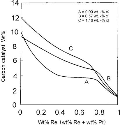
In the literature, it was also observed that the addition of Cl into Pt catalysts produces a decrease in the first peak on TPO spectra that is attributed to coke combustion on metallic sites.[73] It could be due to a decrease in coke amount deposited on Pt sites or to a decrease in the oxidizing capacity of Pt produced by an inhibiting effect of chloride. Chloride also has an impact on coke deposition for bimetallic catalysts. These authors revealed that chlorine would inhibit Pt-Re interaction. The greater the Pt-Re interaction, the lower the deactivation by coking on metallic sites. Taking cyclopentane as a feedstock in this test, it was also reported that incorporation of Re in the reforming catalyst produces a decrease in coke content as shown in Figures 10 and 11. This change is in line with the concomitant decrease in the percentage of cyclopentene (CP22) and cyclopentadiene (CP55) production, which are considered to be coke precursors. It is also seen that amounts of CP22and CP55change in the same way as amounts of coke at constant chloride content. At different chloride levels, however, coke deposition may be enhanced under lower concentrations of those unsaturated intermediates for the catalyst with 1.1% of Cl. These results elucidate that the acid function is especially important under higher chloride content. As for Pt-Sn- reforming catalysts, it was reported that the effect of chlorine in improving dispersion is less pronounced than that of the monometallic Pt catalyst, but it has the additional effect on Pt-Sn alloy formation and thus lower platinum site deactivation by coking.[129]
Residual water must be maintained in the industrial naphtha feed. An alumina-supported reforming catalyst requires moisture to activate the acid
Deactivation by Coking |
415 |
Figure 10 Carbon deposition on catalysts after the run as function of catalyst composition. (From Ref.[73].)
function and provide homogeneous chloride content over the whole catalyst bed. When the environmental atmosphere is too wet, however, chloride in the catalyst may be leached off and thus deteriorate its acidic behavior. Therefore, water control must be performed along with chloride control to maintain a proper chloride–water balance in the environmental atmosphere. From industrial practice, the chloride content on the catalyst should be kept in the range of 0.9– 1.2 wt % for the modern bimetallic catalysts. To meet this requirement an environmental atmosphere of 1–5 ppm of hydrogen chloride and 10–20 ppm of
water should be provided in the circulating gas over the bimetallic reforming catalysts.[130] At lower Cl level, WAIT will need to be raised to maintain octane
number level and hence increase coke deposition. When chloride content is higher than 1.2%, catalyst acidity would be too strong and thus drastically increase the coking rate and shorten the cycle life of a reforming catalyst. Because of the importance of maintaining balance, relationships were given to predict and adjust the amount of chloride that should be injected in the reactor to
416 |
Novaro et al. |
Figure 11 (Cyclopentene þ cyclopentadiene) concentration in the effluent gas as a function of catalyst composition. (From Ref.[73].)
provide an optimal chloride-containing environment in various stages of an industrial unit.[131]
4.6Feed Compositions
Coking is dependent on the structure, boiling point, and basicity of the feedstocks and reformates. The usual feed to the naphtha reforming unit contains 45–70% paraffins, 20–50% naphthenes, 5–15% aromatics, and less than 2% olefins. During the reforming process, the amount of aromatics increases to 60–75%, paraffins and naphthenes decrease to 20–45% and 1–10%, respectively. The olefins almost disappear. Due to different properties, the hydrocarbons produce different effects on coke deposits. Generally, heavy cuts produce more coke.
The n-paraffins are the main components of naphtha feed, and their coking
capacity is important in studying the effects of feed nature on coking process. Parera et al.[132,133] made a detailed measurement of coke formation on pure
hydrocarbons and naphtha doped with several series of hydrocarbons over
Deactivation by Coking |
417 |
different catalysts. They found that light paraffins produce a small amount of cyclopentanes, which are great coke precursors. The heavy paraffins, if they produce bicyclic compounds with an indenic structure, also served as coke producers. Coke formation on several catalysts fed with naphtha and naphtha
doped with 10% of different hydrocarbons is shown in Table 5.
Beltramini et al.[134] reported that when the naphtha is doped with paraffins, e.g., n-heptane, a minimum in coke deposition is formed. Coking deactivation increases, in general, when the number of carbon atoms is higher than 8. Considering aromatics, catalyst deactivation increases with the length of the paraffinic chain linked to the aromatic ring. The ring with five carbon atoms is much more easily polymerized than the one with six carbon atoms; therefore, the 5C atoms ring is an important coke precursor. If the feed contains high concentration of aromatic compounds with 5C atoms ring, more coke will be produced and the catalyst deactivation is rapid.
Olefins are usually poor coke precursors. However, diolefins with conjugated double bonds have greater coking capacity than that of paraffins and monoolefins but are still smaller than that of cyclopentadiene ring. If naphtha contains a ring with 5C atoms, coke formation and catalyst deactivation are higher than for a ring with 6C atoms due to the higher reactivity of 5C atom ring
with dienes to form heavy aromatics.
Ginosar and Subramaniam[135] found that oligomers are important coke precursors during the 1-hexene reforming on a Pt/Al2O3 catalyst. When the 1-hexene feed was diluted with n-pentane and the mixture was run at supercritical conditions, oligomer concentration was significantly reduced, diminishing coke formation.
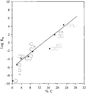
Since most coke on the support is formed by acid–base–catalyzed reactions, the basicity of the feedstock will have an important influence on coke formation. The relationship between these factors was established many years ago. Figure 12 shows the coking rates of a series of aromatic feedstocks as a function of their basicity.[36]
5COKING MECHANISMS
Several assumptions concerning coking mechanisms appeared in the earlier
literature. Some of these results contradict others particularly in the arguments on determination of the long-term deactivation by coking. Shum et al.[137] stated that
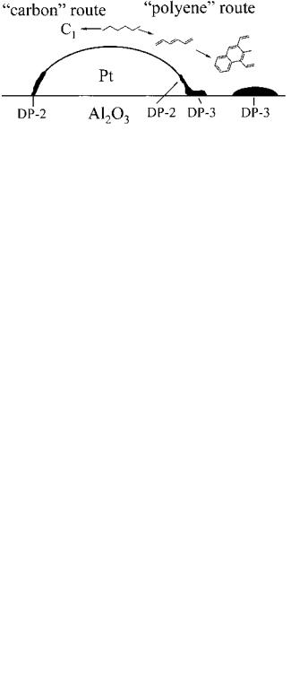
affecting the metallic function by coke controls the long-term deactivation of a reforming catalyst, which is in agreement with the results of Lieske[69] who believed that coking is controlled by a function of metal and not alumina support since the coke formation on alumina without metal remains negligible during the 1-hexane adsorption. Lieske suggested two coke formation routes on the metal function: (1) C1 route: coke formed from C1 species adsorbed on a small part of Pt

Coke Formation on Several Catalysts Fed with Naphtha and Naphtha Doped with 10% Different Hydrocarbons
Catalyst
Pt/Al2O3 |
Pt-Re-S/Al2O3 |
Pt-Ge/Al2O3 |
Al2O3-Cl |
SiO2-Al2O3 |
Pt/SiO2 |
|||||
|
|
|
|
|
|
|
|
|
|
|
3.36 |
(2) |
2.55 |
(2) |
2.60 |
(2) |
0.20 |
(2) |
0.70 |
(2) |
1.01 (2) |
3.75 |
(þ) |
3.08 |
(2) |
3.20 |
(2) |
0.20 |
(2) |
0.68 |
(2) |
1.20 (2) |
9.20 |
(þþ) |
5.68 |
(þ) |
5.96 |
(þ) |
0.54 |
(2) |
1.88 |
(2) |
2.50 (2) |
19.12 |
(þþþ) |
17.10 |
(þþ) |
18.30 |
(þþ) |
11.50 |
(þ) |
20.28 |
(þ) |
5.83 (2) |
3.50 |
(þ) |
3.52 |
(þ) |
3.50 |
(þ) |
0.20 |
|
1.65 |
|
|
7.10 |
(þþ) |
5.13 |
(þ) |
5.94 |
(þ) |
1.09 |
|
3.15 |
(þ) |
|
18.20 |
(þþþ) |
17.06 |
(þþ) |
18.61 |
(þ) |
8.04 |
|
17.38 |
|
|
3.31 |
|
2.87 |
|
2.49 |
|
0.43 |
|
1.47 |
|
1.10 |
3.40 |
|
3.70 |
|
4.35 |
|
0.99 |
|
4.10 |
|
|
3.40 |
|
3.84 |
|
2.61 |
|
4.83 |
|
1.47 |
|
1.10 |
3.20 |
|
1.94 |
|
1.58 |
|
0.36 |
|
0.80 |
|
|
4.09 |
|
3.15 |
|
2.58 |
|
0.22 |
|
0.88 |
|
|
4.35 |
|
3.15 |
|
2.58 |
|
0.22 |
|
0.88 |
|
|
13.10 |
(þþ) |
|
(þ) |
|
|
6.00 |
|
9.21 |
|
|
9.75 |
8.80 |
|
|
|
|
1.09 |
|
|
||
3.80 |
|
3.75 |
|
|
|
|
|
1.00 |
|
|
29.78 |
|
22.34 |
|
|
|
|
|
24.12 |
|
|
9.30 |
|
4.45 |
|
|
|
|
|
2.76 |
|
|
4.24 |
|
4.94 |
|
|
|
|
|
4.37 |
|
|
|
|
|
|
|
|
|
|
|
|
|
418
.al et Novaro
Deactivation by Coking |
419 |
Figure 12 Effect of the basicity of the hydrocarbons on coke formation. (From Ref.[136].)
atoms with high coordination number is mostly formed in the early stage of the reaction and it is a relatively slow process. Nevertheless a very small of amount of such coke can significantly alter the selectivity of the catalyst. (2) Polyene route: more coke was formed on Pt from C6 hydrocarbons in a fast process that leads to significant Pt coverage with coke. During the steady state of coke formation, the coke transformation from Pt to support is the determinant step. A
typical model for production of coke through C1 pathway on platinum and through polyene pathway is shown in Figure 13.[41,138,139]
The viewpoint of metallic sites controlling long-term deactivation was questioned by Margitfalvi who found the long-term deactivation of Pt/Al2O3 was greatly influenced by the deactivation of the acid sites.[140] Parera and
coworkers claimed that the long-term deactivation is due to deactivation of the acid function, which determines the length of the cycle.[141] During an
initial lineout period, the metal function is partially covered by coke and deactivated. Figure 14 shows that the amount of coke on the metal remains constant along all of the operational cycle after the lineout period, and afterward the coke continues to deposit on the acid function, causing final deactivation.[142] The nature of coke formed on the metal also remains the same during the reaction
420 |
Novaro et al. |
Figure 13 A model for production of coke through C1 pathway and through polyene pathway on platinum. (From Ref.[137].)
of 208 days; however, the combustion temperature of the coke formed on the acid support is gradually increased, indicating that the coke on the support is more graphitic as the time on stream increases (Fig. 15).
In fact, in industrial catalytic naphtha reforming, coking is a bifunctional control process. The coke is initially produced through dehydrogenation at faces,
Figure 14 The amount of coke formed on the metal and acid functions. (From Ref.[141].)

Deactivation by Coking |
421 |
Figure 15 The combustion behaviors of the coke formed on the metal and acid functions. (From Ref.[141].) 1) 4 days; 2) 26 days; 3) 49 days; 4) 87 days; 5) 12 days; 6) 161 days, and
7) 208 days.
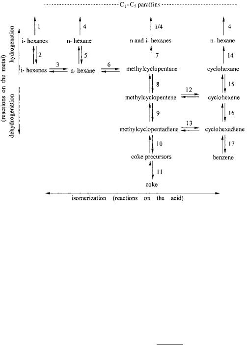
edges, and corners of the metallic particles and then diffuses over the support surface in the form of carbide until reaching the interface between platinum and support. These carbonaceous materials can progress to acid sites to begin the polymerization reaction that transforms it into pseudographite. The aromatic products on the reforming catalyst could further dehydrogenate and polymerize to polynuclear aromatic structures and act as precursors in coke formation.[143] A relatively complete reaction network involving coke formation on both metallic and acidic functions is shown in Figure 16.[71]
6COKING KINETICS
As stated earlier, coke formation is not only governed by the catalyst composition and morphology but also by operating variables, at the level of both the catalyst
422 |
Novaro et al. |
Figure 16 A relatively complete reaction network including coke formation on both metallic and acidic functions. (From Ref.[71].)
particles and the reactors. These complexities cause additional difficulties in kinetic studies and limit the wide application of some models based on relatively simplified assumptions.
Froment[144] developed a general and fundamental kinetic framework on the coke deactivation, that can be used to study site coverage, coke growth and
blockage in pores and networks of pores, and diffusional limitations in catalysts. By using a gravimetric reactor, Mipville[145] found that after an initial period,
coking on an equilibrated Pt/Al2O3 catalyst obeys the following rate law:
r |
coke ¼ |
A P |
H2 |
1 P |
feed |
0:75 C |
coke |
1 exp |
37000 |
|
RT |
||||||||||
|
|
|
|
|
where C is the amount of coke, A is a preexponential term, PH2 is partial pressure of H2, Pf is partial pressure of feed, and T is reaction temperature in Kelvin units. Coking kinetics allows evaluation of coke level for any given time, feedstock, pressure, and reaction temperature.
Deactivation by Coking |
423 |
Under an accelerated deactivation condition, the relationship between the
amount of coke formed on Pt/Al2O3 catalyst and several operational conditions could be expressed as the following:[146]
%C ¼ 4:99 106e 8955=TP 0:94WHSV 1:28 |
H2 |
1:33 |
|
|
naphtha
This equation shows that the coke amount increases by increasing the temperature and by decreasing pressure, space velocity, and H2-to-naphtha ratio.
The coking rates of the reversible and irreversible coke on metallic function, rrev and rirre, are different, which may be expressed as follows:[46]
rrev ¼ krev PM f (a)w |
1 |
(a) ¼ |
½M0&kp½P&aw 31 (a)f (a) |
3 |
1 þ KH½H2&1=2 þ KA½A& þ KB½B& þ Kp½P& |
rirre ¼ kirrCrevw 13 (a)
where the function w 13 (a) accounts for the probability of finding platinum ensembles containing at least 2–4 Pt atoms, which is the minimal site requirement for typical coking mechanisms. Function f (a) accounts for the higher coking rate on the more energetic sites, which are covered initially. This accounts for the effect of the metal atom ensembles on coking.
From the practical viewpoint, lumping kinetic models may be more suitable for application in the naphtha reforming process.[47,148] Recently, some
lumping kinetic models, which were extended to include coking deactivation, have been developed.[149 – 151] Jiang et al. developed a coking deactivation model based on a 16-lump kinetic model. The authors claimed that this model could be used to predict the product distribution before and after accelerated coking deactivation and to determine the effects of the operation parameters on coke deactivation.
Ramage et al. developed a 13-lump kinetic model in which the catalyst deactivation by coking was taken into account.[152] This model included
hydrocarbon conversion kinetics on fresh catalysts and the modification of the kinetics with time on stream due to catalyst deactivation. A set of three reactors were used to test this kinetics model and results show that it can be used to predict the product distribution, activity, and selectivity.
Tasker and Riggs[153] reported a detailed kinetic scheme involving 35 pseudocomponents connected by a network of 36 reactions within C5 –C10 range in a semiregenerative catalytic naphtha reformer, which was modeled by using Hougen–Watson Langmuir–Hinshelwood reaction rate expressions. Deactivation of the catalyst was modeled by including the corresponding equations for coking kinetics. This model was benchmarked with the industrial
424 |
Novaro et al. |
data to ensure that it adequately represented the actual plant variables at a base operating point.
7EFFECTS OF COKING ON ACTIVITY AND SELECTIVITY
The overall reforming process involves various reactions. Isomerization, cyclization, and aromatization are desired but the hydrocleavage reactions are not. The metallic function is mainly responsible for hydrogenation–dehydro-
genation and hydrogenolysis activity, while the acidic support provides activity for the cracking, isomerization, and aromatization.[20,154] Coking on the
metallic function and on the acidic function will directly affect the selectivity of the above reactions.
Since the reactions of dehydrocyclization and hydrogenolysis are mainly controlled by the metallic functions; therefore, the selectivity of these reactions must relate to the coking process on metal. The rates of both reactions usually undergo a rapid initial deactivation and then remain constant up to the end of the operation cycle. However, the relative activity of n-heptane dehydrocyclization to toluene is found to be a simultaneous combination of monometallic mechanism and a bifunctional one controlled by acid function. The conversion rate is initially deactivated by a small amount of coke on metallic sites, and the subsequent
linear deactivation should correspond to the bifunctional acid–controlled mechanism.[155]
Isomerization is a typical bifunctional reaction controlled by the acid function of the catalyst. The catalytic activity of the n-pentane isomerization linearly decreases with the amount of carbon deposited on the acid function of the catalyst. Hydrocracking reaction usually shows a large deactivation resulting from a small amount of deposited carbon and then deactivates linearly with carbon accumulation. The initial deactivation coincides with loss of the metallic function and the coking of the acid function causes linear deactivation.[133]
An important chemical property of the carbonaceous deposit on the catalyst is its ability to store and exchange hydrogen with reacting surface species, producing hydrogen spillover from metallic sites to adsorbed species or the reverse from adsorbed species. This also influences the selectivity and activity. Electronic or geometrical effects may explain the coke effect on activity and selectivity. Coke can donate electron charge to Pt that enhances electron density of Pt, and this favors reactions of weaker secondary C22H bonds more than
stronger primary C22H bonds in hydrocarbon reactions, altering the isomerization products distribution.[129,156] However, the geometrical effect of coke may
be dominant in comparison with the electronic one. The blocking of lowcoordination Pt sites by coking decreases the aromatization selectivity.[129]
Deactivation by Coking |
425 |
8CONCLUSIONS
Although coking is a very complex process, some important conclusions can be obtained based on the studies of model and industrial reforming catalysts and processes. These can be summarized as follows:
Coke can be formed on both the metallic function and on the acid sites on the support. During the lineout stage, coke is mainly deposited on the metal particles. Then it transfers to the acid sites on the support where a more graphitic-like structure is produced through complex acid-base catalyzed reactions. Coke can be formed on the metal function through C1 or/and polyene pathways.
Coke distributions on the metal crystallites, catalyst support across the catalyst pellet, reactor inner surface, and within the catalyst bed are greatly heterogeneous. Coke buildup along the catalyst bed is mainly determined by reaction conditions and coking mechanisms.
Metallic content, crystallite size, and dispersion show important influences on coke formation. Increasing metal loading generally leads to an increase in coke amount. The high metallic dispersion can reduce the coke amount. Coke is preferentially formed on the larger metallic crystallites with high coordination. The metallic crystallites with low coordination show more resistance to coking than the others.
The structure, surface area, and acidity of the catalyst support are important factors in coke formation. Increasing acidity of the support may increase coke amount and alter coke combustion behaviors.
The coke formation is affected by the addition of promoters. The second metal additives, such as tin, rhenium, and others, can inhibit coke accumulation and modify the coke nature by means of electronic or geometrical effects. Metal addition may destroy the coke precursors and induce a preferential desorption of coke on the support and thus improve the catalyst stability.
The presence of chlorine produces more uniform deposition of Pt over alumina in the Pt/Al2O3 catalyst and thus improves the dispersion of the metallic phase. However, as chloride on the support it increases coke deposition. There is an optimal chloride content on the reforming catalyst, which allows a reduction of the coke deposit through a mechanism involving the hydrogen spillover from metal to the support and better metallic dispersion. The presence of sulfur poisons catalyst active sites, altering the resultant coke nature and location. Presulfurization is an effective and necessary method to passivate the hydrogenolytic hyperactivity of the reforming catalyst in the initial periods of startup. Compositions of the naphtha-reforming feedstock are another factor affecting coke formation. Generally heavier cuts produce more coke, and the higher the basicity of the feed hydrocarbons, the more the coke amount on the catalysts.
426 |
Novaro et al. |
Reaction parameters such as temperature, pressure, time on stream, and hydrogen-to-oil ratio are closely related to coke depositions. Increasing reaction temperature usually causes an increase in coke amount. When the reaction is under high pressure, coke shows a more dehydrogenated and graphitic nature. Decreasing space velocity, similar to decreasing the H2/HC ratio at constant pressure, produces more coke deposition on the support.
SYMBOLS
Apre-exponential term
[A] |
concentration of reactant in gas phase |
[B] |
concentration of product in gas phase |
Ccoke amount
krev |
coking rate constant for the reversible coke |
kirre |
coking rate constant for the irreversible coke |
KH |
equilibrium chemisorption constant for reactant |
KA |
equilibrium chemisorption constant for product |
KB |
equilibrium chemisorption constant for hydrogen |
Kp |
equilibrium chemisorption constant for coke precursors |
PH2 |
partial pressure of hydrogen |
Pf |
partial pressure of feedstock |
[P] |
gas concentration of the coke precursor |
[M0] |
initial concentrations of the metal sites |
rcoke |
coking rate |
rrev |
rate of reversible coke formation |
rirr |
rate of irreversible coke formation |
T |
reaction temperature, K |
w1=3(a): |
the probability of finding platinum ensembles containing at least |
|
2–4 Pt atoms |
f (a) |
function describing exponential decay of activity with increasing |
|
metal surface coverage |
REFERENCES
1.Matusek, K.; Wootsch, A.; Zimmer, H.; Paa´l, Z. Appl. Catal. A: Gen. 2000, 191, 141.
2.Garin, F.; Maire, G.; Zyade, S.; Zauwen, M.; Frennet, A.; Zielinski, P. J. Mol. Catal. 1990, 58, 185.
3.Menon, P.G. J. Mol. Catal. 1990, 59, 207.
Deactivation by Coking |
427 |
4.(a) Dives, S.M.; Zaera, F.; Somorjai, G.A. J. Catal. 1982, 77, 439; (b) Mare´cot, P.; Barbier, J. In Catalytic Naphtha Reforming: Science and Technology; Antos, G.J., Aitani, A.M.; Parera, J.M., Eds.; Marcel Dekker: New York, 1995; 279 pp;
(c) Davis, B.H.; Antos, G.J. In Catalytic Naphtha Reforming: Science and Technology; Antos, G.J., Aitani, A.M., Parera, J.M., Eds.; Marcel Dekker: New York, 1995; 113 pp.
5.Augustine, S.M.; Alameddin, G.N.; Sachtler, W.M.H. J. Catal. 1989, 115, 217.
6.(a) Querini, C.A.; Fung, S.C. Appl. Catal. 1994, 117, 53; (b) Querini, C.A.; Fung, S.C. Catal. Today 1997, 37, 277.
7.Eberly, P.E.; Kimberlin, C.N.; Miller, W.H.; Drushel, H.V. Ind. Eng. Chem. 1966, 5, 193.
8.Best, D.A.; Wojciechowski, B.W. J. Catal. 1977, 47, 11.
9.Parmaliana, A.; Frusteri, F.; Nesterov, G.A.; Paukshtis, E.A.; Giordano, N. In Catalyst Deactivation; Delmon, B., Froment, G.F., Eds.; Elsevier: Amsterdam, 1987; 198 pp.
10.Li, C.L.; Novaro, O.; Bokhimi, X.; Mun˜oz, E.; Boldu´, J.L.; Wang, J.A.; Lopez, T.; Go´mez, R.; Batina, N. Catal. Lett. 2000, 65, 209.
11.Yao, H.C.; Shelef, M. J. Catal. 1976, 140, 392.
12.Anderson, J.A.; Chong, F.K.; Rochester, C.H. J. Mol. Catal. A: Gen. 1999, 140, 65.
13.Kalinina, N.G.; Poluboyarov, V.A.; Anufrienko, V.F.; Ione, K.G. Kinet. Catal. 1986, 27, 215.
14.Parera, J.M.; Figoli, N.S.; Beltramini, J.N.; Churin, E.J.; Cabrol, R.A. Proceedings of the 8th International Congress on Catalysis; Berlin, 1984; 93 pp.
15.Liu, F.; Shen, G.Q.; Li, C.L. J. East China Inst. Chem. Technol. 1993, 19 (2), 138.
16.Li, C.L.; Novaro, O.; Mun˜oz, E.; Boldu´, J.L.; Bokhimi, X.; Wang, J.A.; Lopez, T.; Go´mez, R. Appl. Catal. A: Gen. 2000, 199, 211.
17.Tuinstra, F.; Koenig, J.L. J. Chem. Phys. 1970, 53 (3), 1126.
18.Nakamizo, M.; Honda, H.; Inagaki, M. Carbon 1978, 16, 281.
19.Espinat, D.; Dexpert, H.; Freund, E.; Martino, G.; Couzi, M.; Lespade, P.; Cruege, F. Appl. Catal. 1985, 16, 343.
20.Barbier, J. Appl. Catal. 1986, 23, 225.
21.Espinat, D.; Fround, E.; Dexpert, H.; Martino, G. J. Catal. 1990, 126, 496.
22.Figoli, N.S.; Beltramini, J.N.; Querini, C.A.; Parera, J.M. Appl. Catal. 1986, 26, 39.
23.Cabrol, R.A.; Oberlin, A. J. Catal. 1984, 89, 156.
24.Gallezot, P.; Leclercq, C.; Barbier, J.; Marecot, P. J. Catal. 1989, 16, 164.
25.Chang, T.S.; Rodriguez, N.M.; Baker, R.T.K. J. Catal. 1990, 116, 164.
26.Beltramini, J.N.; Wessel, T.J.; Datta, R. In Catalyst Deactivation; Bartholomew, C.H., Butt, J.B., Eds.; Elsevier: Amsterdam, 1991; 119 pp.
27.Arteage, G.J.; Anderson, J.A.; Rochester, C.H. Catal. Lett. 1999, 58, 189.
28.(a) Butt, J.; Petersen, E.E. Activation, Deactivation and Poisoning of Catalyst; Academic Press: London, 1998; (b) Froment, G.F.; Bishoff, K.B. Chem. Eng. Sci. 1962, 17, 105; (c) Acharya, D.R.; Ghassemi, M.R.; Hughes, R. Appl. Catal. 1990, 58, 53.
29.(a) Querini, C.A.; Fung, S.C. J. Catal. 1993, 141, 389; (b) Querini, A.; Fung, S.C. J. Catal. 1996, 161, 263.
428 |
Novaro et al. |
30.Beltramini, J.N.; Datta, R. React. Kinet. Catal. Lett. 1991, 44 (2), 345.
31.Beltramini, J.N.; Churin, E.J.; Traffano, E.M.; Franck, J.P. Appl. Catal. 1985, 19, 169.
32.Barbier, J. Appl. Catal. 1985, 23, 225.
33.Datka, J.; Eischens, R.P. In Catalyst Deactivation; Bartholomew, C.H., Butt, J.B., Eds.; Elsevier: Amsterdam, 1991; 127 pp.
34.Barbier, J.; Gorro, G.; Zhang, Y. Appl. Catal. 1985, 13, 245.
35.Marecot, P.; Churin, E.; Barbier, J. React. Kinet. Catal. Lett. 1988, 37, 233.
36.Barbier, J.; Chuin, E.; Mae´cot, P. J. Catal. 1990, 126, 228.
37.Davis, S.M.; Zaera, F.; Somorjai, G.A. Appl. Catal. 1982, 77, 439.
38.Somorjai, G.A.; Blakely, D.M. Nature 1975, 258, 580.
39.Gallezot, P., Datka, J.; Massardier, J.; Primet, M.; Imelik, B. Proceedings of 6th International Congress on Catalysis; Hightower, J.W., Ed.; London, 1976; 696 pp.
40.Barbier, J.; Marecot, P. Appl. Catal. 1986, 102, 21.
41.Trimm, D.L. Appl. Catal. 1983, 5, 263.
42.Christmann, K.; Ertl, G. Surf. Sci. 1976, 60, 366.
43.Van Broekhoven, E.H.; Schoonhoven, J.W.F.M.; Ponec, V. Surf. Sci. 1985, 156, 899.
44.Ponec, V. Adv. Catal. 1983, 32, 149.
45.Van Broekhoven, E.H.; Schoonhoven, J.W.F.M.; Ponec, V. Surf. Sci. 1985, 156, 899.
46.Biswas, J.; Gray, P.G.; Do, D.D. Appl. Catal. 1987, 32, 249.
47.Salmeron, M.; Somorjai, G.A. J. Phys. Chem. 1982, 86, 341.
48.(a) Standard Oil Company. US Patent 2,848,377, 1953; (b) French Patent 2,372,883, 1976; (c) UOP. US Patent 3,511,888, 1970; (d) CFR (Compagnie Franc¸aise de Raffinage), French Patent 2,031,984, 1969; (e) Chevron, US Patent 3,415,777, 1968; (f) Beltramini, J.; Trimm, D.L. Appl. Catal. 1987, 32, 71.
49.Borgna, A.; Garetto, T.F.; Apesteguı´a, C.R. Appl. Catal. A: Gen. 2000, 197, 11.
50.Burch, R.; Mitchell, A.J. Appl. Catal. 1983, 6, 121.
51.Baucaud, R.; Barbier, J.; Blanchard, G.; Charcosset, H. J. Chem. Phys. 1980, 77, 387.
52.Rice, R.W.; Lu, K. J. Catal. 1982, 77, 104.
53.Zhdan, P.A.; Kuenestsov, B.N.; Shepelin, A.P.; Kovalchuk, V.I.; Yermakov, Yu.I. React. Kinek. Catal. Lett. 1981, 18, 267.
54.Muller, A.C.; Engelhard, P.A.; Weisang, J.E. J. Catal. 1979, 56, 65.
55.Burch, R.; Carla, L.C. J. Catal. 1981, 71, 348.
56.Carter, J.L.; McVicker, G.B.; Weissman, M.; Kmak, W.S.; Sinfelt, J.H. Appl. Catal. 1982, 3, 327.
57.Bacaud, R.; Bussiere, P.; Figueras, F. J. Catal. 1979, 69, 399.
58.Rasser, J.C.; Beindorff, W.H.; Scholten, J.J.F. J. Chem. Res. 1979, 62.
59.Zhorov, Yu.M.; Panchenkov, G.M.; Kartashev, Yu.N. Kinet. Catal. 1981, 22, 1058.
60.Johnson, M.F.L.; LeRoy, V.M. J. Catal. 1974, 35, 434.
61.Beltramini, J.; Trimm, D.L. Appl. Catal. 1987, 31, 113.
62.Lieske, H.; Sa´rka´ny, Vo¨lter, J. Appl. Catal. 1987, 30, 69.
63.Vo¨lter, J.; Ku¨rschner, U. Appl. Catal. 1983, 8, 167.
64.Barbier, J. Stud. Surf. Sci. Catal. 1987, 34, 1.
65.Grau, J.M.; Parera, J.M. Appl. Catal. 1991, 70, 9.
Deactivation by Coking |
429 |
66.Tennison, S.R. Chem. Br. 1981, 536.
67.Dowden, D.A. Chem. Soc. Spec. Publ. Catal. 1978, 1.
68.Shum, V.K.; Butt, J.B.; Sachtler, W.M.H. J. Catal. 1986, 96, 371.
69.Shum, V.K.; Butt, J.B.; Sachtler, W.M.H. J. Catal. 1986, 96, 126.
70.Carter, J.L.; McVicker, G.B.; Weisshan, K.; Hmak, W.S.; Sinfelt, J.H. Appl. Catal. 1982, 327.
71.Parera, J.M.; Beltramini, J.N.; Querini, C.A.; Martinell, E.E.; Churin, E.J.; Aloe, P.E.; Figoli, N.S. J. Catal. 1986, 99, 39.
72.Barbier, J.; Marecot, P.; Pieck, C.L. In Catalyst Deactivation; Bartholomew, C.H., Fuentes, G.A., Eds.; Elsevier: Amsterdam, 1997; 327 pp.
73.Pieck, C.L.; Marecot, P.; Prera, J.M.; Barbier, J. Appl. Catal. A: Gen. 1995, 126, 153.
74.Pieck, C.L.; Marecot, P.; Barbier, J. Appl. Catal. A: Gen. 1996, 145, 323.
75.Traffano, E.M.; Parera, J.M. Appl. Catal. 1986, 28, 193.
76.Barbier, J. Appl. Catal. 1986, 23, 225.
77.Artraga, G.J.; Anderson, J.A.; Rochester, C.H. J. Catal. 1999, 187, 219.
78.Augustine, S.M.; Alameddin, G.N.; Sachtler, W.M.H. J. Catal. 1989, 115, 217.
79.Gallezot, P.; Leclercq, C.; Barbier, J.; Mare´cot, P. J. Catal. 1989, 116, 164.
80.Parmaliana, A.; Frusteri, F.; Nesterov, G.A.; Paukshtis, E.A.; Giordano, N. In Catalyst Deactivation; Delmon, B., Froment, G.F., Eds.; Elsevier: Amsterdam, 1987; 197 pp.
81.Barbier, J.; Elassal, L.; Gnep, N.S.; Guisnet, M.; Molina, W.; Zhang, Y.R.; Bournonville, J.P.; Franck, J.P. Bull. Soc. Chim. Fr. 1984, 9–10, 1250.
82.Svajgl, O. Int. Chem. Eng. 1972, 12 (1), 55.
83.Aranda, D.A.G.; Alfonso, J.C.; Frety, R.; Schmal, M. In Catalyst Deactivation; Bartholomew, C.H., Fuentes, G.A., Eds.; Elsevier: Amsterdam, 1997; 335 pp.
84.Fan, Y.-N.; Xu, Z.-S.; Zang, J.-L.; Lin, L.-W. In Catalyst Deactivation; Bartholomew, C.H., Butt, J.B., Eds.; Amsterdam, 1991; 683 pp.
85.Parmaliana, A.; Frusteri, F.; Nesterov, G.A.; Paukshtis, E.A.; Giordano, N. In Catalyst Deactivation; Delmon, B., Froment, G.F., Eds.; Elsevier: Amsterdam, 1987; 197 pp.
86.Dossi, C.; Tsang, C.M.; Sachtler, W.M.H. Energy Fuels 1989, 3, 468.
87.Martens, J.A.; Tielen, M.; Jacobs, P.A. Stud. Surf. Sci. Catal. 1985, 46, 49.
88.Smirniotis, P.G.; Ruckenstein, E. Catal. Lett. 1993, 17, 341.
89.Smirniotis, P.G.; Ruckenstein, E. J. Catal. 1993, 140, 526.
90.Smirniotis, P.G.; Ruckenstein, E. Chem. Eng. Sci. 1993, 48, 3263.
91.Fang, X.-G.; Li, F.-Y.; Luo, L.-T. Appl. Catal. A: Gen. 1996, 146, 297.
92.Sugimoto, M.; Katsuno, H.; Hayasaka, T.; Hirasawa, K.; Ishiawa, N. Appl. Catal.
1993, 106, 9.
93.Hughes, T.R.; Buss, W.S.; Tamm, P.W.; Jacobson, R.J. Stud. Surf. Sci. Catal. 1986, 28, 725.
94.Tamm, P.W.; Mohr, D.H.; Detz, C.R. Energy Progress 1987, 7 (4), 215.
95.Hill, J.M.; Cortright, R.D.; Dumesic, J.A. Appl. Catal. A: Gen. 1998, 168, 9.
96.Smirniotis, P.G.; Ruckenstein, E. Appl. Catal. A: Gen. 1995, 123, 59.
97.Little, D.M. Catalytic Reforming; Penn Well Publishing: Tulsa, OK, 1985; 88 pp.
430 |
Novaro et al. |
98.Barbier, J.; Churin, E.; Marecot, P.; Menezo, J.C. Appl. Catal. 1988, 36, 277.
99.Bakulin, R.A.; Levinter, M.E.; Unger, F.G. Neftekhimiya 1974, 14 (5), 707.
100.Parera, J.M.; Figoli, N.S.; Traffano, E.M.; Beltramini, J.N.; Martinelli, E.E. Appl. Catal. 1983, 5, 33.
101.Barbier, J. In Catalyst Deactivation; Delmon, B., Fromont, G.F., Eds.; Elsevier: Amsterdam, 1987; 1 p.
102.Pieck, C.L.; Parera, J.M. Ind. Eng. Chem. Res. 1989, 28, 1785.
103.Liang, W.J. Petroleum Chemistry; Petroleum University Publisher: China, 1995; 342 pp.
104.(a) Zhorob, Y.M.; Panchenkov, G.M.; Kertashev, Y.N. Kinet. Catal. 1986, 22, 1058; (b) Biswas, J.; Bickle, G.M.; Gray, P.G.; Do, D.D.; Barbier, J. Catal. Rev. Sci. Eng. 1988, 30 (2), 161.
105.Wang, C.D.; Zhang, D.Q.; Sun, Z.L. Petroleum Proc. Petrochem. (China) 2000, 31 (7), 13.
106.Huang, G.H.; Shan, Q.S.; Zhu, Y.Q.; Yang, S.H. Ibid. 2000, 31 (7), 5.
107.Barias, O.A.; Holmen, A.; Blekkan, E.A. J. Catal. 1996, 158, 1.
108.Larsson, M.; Hulten, M.; Blekkan, E.A.; Anderson, B.D. J. Catal. 1996, 164, 44.
109.Ji, L. Petroleum Proc. Petrochem. (China) 1997, 28 (9), 32.
110.Marecot, P.; Barbier, J. In Catalytic Naphtha Reforming; Antos, G.J., Aitani, A.M., Parera, J.M., Eds.; Marcel Dekker: New York, 1995, 279 pp.
111.Borgna, A.; Garetto, T.F.; Apesteguia, C.R. Appl. Catal. A: Gen. 2000, 197, 11.
112.Van Trimpont, P.A.; Marin, G.B.; Froment, G.F. Appl. Catal. 1985, 17, 161.
113.Parera, J.M.; Verderone, R.J.; Pieck, C.L.; Traffano, E.M. Appl. Catal. 1986, 23, 15.
114.Apesteguia, C.R.; Barbier, J. J. Catal. 1982, 78, 352.
115.Kluksdahl, H.E. US Patent No. 3,617,520, 1971.
116.Jacobson, R.L. US Patent No. 3,578,582, 1971.
117.Lowell, P.F. U.S. Patent No.3,565,789, 1971.
118.Apesteguia, C.R.; Barbier, J. J. Catal. 1982, 78, 252.
119.Augustina, S.M.; Alameddim, G.N.; Sachtler, W.M.H. J. Catal. 1989, 115, 217.
120.Coughlim, R.W.; Hasan, A.; Kwakami, K. J. Catal. 1988, 88, 163.
121.Wilde, M.; Stolz, T.; Feldhamsa, R.T.; Ander, K. Appl. Catal. 1987, 31, 99.
122.Figueiredo, J.L. Progress in Catalyst Deactivation; Figueiredo, J.L., Ed.; 1982; 45 pp.
123.Shum, V.K.; Butt, J.B.; Sachtler, W.M.H. Appl. Catal. 1984, 11, 151.
124.Gjervan, T.; Prestvik, R.; Totdal, B.; Lyman, C.E.; Holmen, A. Catalyst Today 2001, 65, 163.
125.Ardiles, D.R.; de Miguel, S.R.; Castro, A.A.; Scelza, O.A. Appl. Catal. 1986, 24, 175.
126.Fernandez-Garcia, M.; Chong, F.K.; Anderson, J.A.; Rochester, C.H.; Haller, G.L. J. Catal. 1999, 182, 199.
127.Cooper, B.J.; Trimm, D.L. In Catalyst Deactivation; Delman, B., Froment, G.F., Eds.; Elsevier: Amsterdam, 1980; 63 pp.
128.Parera, J.M.; Figoli, N.S.; Jablonski, F.L.; Sad, M.R.; Beltramini, J.N. Stud. Surf. Sci. Catal. 1980, 6, 571.
129.Arteaga, G.J.; Anderson, J.A.; Rochester, H. J. Catal. 1999, 187, 219.
Deactivation by Coking |
431 |
130.Little, D.M. Catalytic Reforming; Penn Well Publishing: Tulsa, OK, 1985; 108 pp.
131.Dai, C.Y. Acta Petrolei Sinica (Petroleum Processing Section) 1995, 11 (3), 96.
132.Parera, J.M.; Verderone, R.J.; Querini, C.A. In Catalyst Deactivation; Delmon, B.; Froment, G.F., Eds.; Elsevier: Amsterdam, 1987; 135 pp.
133.Parera, J.M.; Querini, C.A.; Beltramini, J.N.; Figoli, N.S. Appl. Catal. 1987, 32, 117.
134.Beltramini, J.N.; Cabrol, R.A.; Churin, E.J.; Figoli, N.S.; Martinelli, E.E.; Parera, J.M. Appl. Catal. 1985, 17, 65.
135.Ginosar, D.M.; Subramaniam, B. J. Catal. 1995, 152, 31.
136.Appleby, W.G.; Gibson, J.W.; Good, G.M. Ind. Eng. Chem. Proc. Des. Dev. 1962, 1, 102.
137.Shum, V.K.; Butt, J.B.; Sachtler, W.M.H. Appl. Catal. 1984, 11, 151.
138.Sarkany, A.; Lieske, H.; Szilagyi, T.; Toth, L. Proceedings of the 8th International Congress on Catalysis; Berlin, 1984; Vols. 1 and 2, 613 pp.
139.Luck, F.; Aejyach, S.; Marie, G., Proceedings of the 8th International Congress on Catalysis; Berlin, 1984; 234 pp.
140.Margitfalvi, J.; Go¨bo¨lo¨s, S. Appl. Catal. 1988, 36, 331.
141.Parera, J.M.; Querini, C.; Figoli, N.S. Appl. Catal. 1988, 44, L1-L8.
142.Parera, J.M. In Catalyst Deactivation; Bartholomew, C.H., Butt, J.B., Eds.; Elsevier: Amsterdam, 1991; 103 pp.
143.Parera, J.M. In Catalyst Deactivation; Delmon, B., Froment, G.F., Eds.; Elsevier: Amsterdam, 1987; 135 pp.
144.Froment, C.F. In Catalyst Deactivation; Bartholomew, C.H., Butt, J.B., Eds.; Elsevier: Amsterdam, 1991; 53 pp.
145.Mipville, R.L. In Catalyst Deactivation; Bartholomew, C.H., Butt, J.B., Eds.; Elsevier: Amsterdam, 1991; 151 pp.
146.Figoli, N.S.; Beltramini, J.N.; Martinelli, E.E.; Sad, M.R.; Parera, J.M. Appl. Catal. 1983, 5, 19.
147.Ramage, M.P.; Graziani, K.R. Chem. Eng. Sci. 1980, 35 (1), 41.
148.Froment, G.F. AIChE J. 1975, 21 (6), 1041.
149.Jiang, H.-B.; Wong, H.-X. J. East China Univ. Sci. Technol. 1998, 24 (1),42.
150.Jiang, H.-B.; Wong, H.-X. J. East China Univ. Sci. Technol. 1998, 24 (1), 46.
151.Xie, X.-A.; Ping, S.-H.; Lui, T.-J. China Refinery Design 1996, 26 (2), 44.
152.Ramage, M.P.; Graziani, K.R.; Schipper, P.H.; Krambeck, F.J.; Choi, B.C. Adv. Chem. Eng. 1987, 13, 193.
153.Tasker, U.; Riggs, J.B. AIChE J. 1997, 43, 740.
154.Molina, W.; Guisnet, M.; Barbier, J.; Gnep, N.S.; Elassal, L. First FrancoVenezuelan Congress, 1993.
155.Gates, B.C.; Katzer, J.R.; Schuit, G.C. Chemistry of Catalytic Processes; McGrawHill: New York, 1979; 1984 pp.
156.Hlavathy, Z.; Te´te´nyi, P. Surf. Sci. 1998, 410, 39.