

14
Control Systems for Commercial Reformers
Lee Turpin
Aspen Technology, Inc.
Bothell, Washington, U.S.A.
1INTRODUCTION
The typical catalytic reforming process is designed to convert a low-aromatics naphtha feedstock to a stabilized reformate stream high in aromatics. Commercial reformer units consist of a reactor section and a fractionation section. The reactor section consists of a feed system, several pairs of heaters, and reactors in series followed by a flash drum. A portion of the flashed hydrogen is recycled to the feed prior to entering the first heater. The flash liquid is then sent to the fractionation section with a distillation tower frequently referred to as the stabilizer. Some units incorporate a recontactor section to increase the hydrogen purity of the net gas stream. The light ends are stripped from the flash liquid to form an off-gas and a liquefied petroleum gas (LPG) stream off of the top of the stabilizer. The stabilizer bottoms product is referred to as the reformate. Several heater reactor pairs are used in the process to maintain the reactor temperature profiles within an operating range of roughly 750–9508F (400–5008C). To achieve these relatively simple tasks in a commercial environment requires a complex set of integrated systems referred to as the management of a catalytic reformer.
Management of a commercial reformer operation has two primary and equally important objectives. One objective is to maintain a safe operation of the process, and the other objective is to run the process in a manner that meets the overall processing requirements for the facility. The safe operation of the process unit covers a variety of issues, foremost of which is the safety of the operators, maintenance workers, and other personnel within the operating facility. Included
497

498 |
Turpin |
in the general objective of safe operation is sustaining an operation that ensures the structural integrity of the owner’s capital investment in process equipment. The processing objective includes operating at the planned conversion of the feedstock and meeting government requirements such as protection of the environment. To meet the primary and other supplementary operating objectives, a catalytic reformer is controlled by a management continuum as represented by Figure 1. Note that one end of the continuum is basic measurements of process variables such as temperature, pressure, and flow. The other end of the continuum is the economic planning function. Figure 1 is a representative drawing that shows a partial set of the control functions found in a catalytic reformer process unit. Note that there are two distinct paths through the management continuum, one for each objective; one path for safe operation of the unit and the second for control of the unit to meet processing objectives. Providing continuity from one end of the continuum to the other is a set of interlinked control systems. Some of the control systems are automated with traditional instrumentation, and some are supervisory systems implemented with the unit’s operating staff. The control systems are tools designed to work together to assist in the management of the unit operation. As the catalytic reformer control systems are further integrated with technology such as regulatory controllers, advanced process control (APC), and real-time online optimization (RT-OPT), the mundane human interactions with the basic regulatory controls are reduced. However, ultimate control by humans is not eliminated. The controllers can be viewed as chained technology packages, each linked to adjacent packages to refine the overall control of the process.
All of the common control systems found in the management of catalytic reformers are discussed in this chapter, with the objective of giving an overall picture of the interlinking of these control systems. More detail is given to automated control systems that are unique to the catalytic reforming process. The fundamental control systems are the same for all catalytic reformers, regardless of mechanical configuration. In those instances where the mechanical configurations require unique control system designs, the control systems are presented as exceptions to the typical controls.
Figure 1 The management continuum.

Control Systems for Commercial Reformers |
499 |
The following section on fundamental control systems for commercial reformers presents material applicable to all reformer operations. The objective of the discussion is to present information on the different control systems incorporated into the management of a catalytic reformer. The section on APC of catalytic reformers discusses the requirements, benefits, and techniques used in the application of advanced process control to catalytic reformers. The final section on RT-OPT of catalytic reformers presents information on the types of optimization systems available, where they are applicable, and the techniques used to implement an RT-OPT into the overall control system architecture.
2FUNDAMENTAL CONTROL SYSTEMS FOR COMMERCIAL REFORMERS
From an instrumentation and control perspective, the process unit is limited to the reactor section and primary separation section in this chapter. The reactor section consists of the feed control, feed/effluent exchangers, fired heaters, reactors, effluent cooler, product separator, and recycle compressor. For the case of continuous catalyst circulation units, the catalyst regeneration section will be covered in the APC and optimization sections. Moving from the primary instruments along the management continuum are the fundamental regulatory control systems. These systems follow two parallel paths as shown in Table 1, both taking process measurements from the primary instruments.
2.1.Basic Regulatory Control Systems
All of the control systems are built on measurements of the process conditions. Primary instrumentation in commercial catalytic reformers consists of basic temperature, pressure, and flow transmitters integrated with single-loop proportional integral (PI) and proportional integral derivative (PID) controllers. More sophisticated online analyzers are incorporated into some units.
Conventional orifice plates are used for flow measurements. Pressure is usually measured using force-type pressure sensors. Type J thermocouples are
Table 1 Fundamental Control Systems
Process control systems |
Safety systems |
|
|
Fundamental regulatory control system |
Equipment shutdown systems |
Supervision control systems |
Emergency shutdown systems |
Planning and scheduling function |
|
|
|
500 |
Turpin |
used for temperature measurement in cold service and type K thermocouples in hot service. Duplicate sensors are often installed to provide redundant readings for the safety systems. The standard primary sensing elements have been selected to meet three criteria: (1) producing products on specification, (2) equipment protection, and (3) personnel protection, with attention given to capital cost, reliability, and ease of maintenance. The level of accuracy is determined by the point needed to safely monitor and operate the facility.
The majority of catalytic reformer control systems include an on-line analyzer for the recycle gas hydrogen concentration. Frequently an analyzer for recycle gas moisture is also installed. Other process analyzers are used, but infrequently.
Traditional Control Systems
The traditional control systems consist of a number of individual single-task control and monitoring instruments. Control rooms have banks of instrument packages, each processing a separate control function. In some cases multiple sensor readings (such as temperatures) may be collected into a single display mechanism. Sensor readings are either transformed in the field to a usable measurement (torsion to pressure), or are collected and transformed in an instrument located in the control room (emf from a thermocouple to temperature via a Wheatstone bridge). Sensor readings that are used for feedback in a control loop are normally limited to that instrument. All of the controllers are singleinput, single-output PI or PID control loops. Controllers can be cascaded from one controller to the next, but only within the limitations of PI or PID control [1].
The time to steady state (TSS) in all of the catalytic reformer control loops is sufficiently short to allow a traditional control system to support the implementation of PI and PID controllers. Some controls, such as heater excess air control, cannot be implemented safely within the confines of the basic instrumentation.
In the operation of catalytic reformers, a traditional control system is perfectly adequate for performing basic regulatory tasks. The traditional control system is not adequate for supporting more sophisticated control technology such as APC, expert advisor systems, and on-line optimization.
Distributed Control Systems
A distributed control system (DCS) performs all of the same basic functions of the traditional control system, but a DCS system processes sensor signals and handles the control functions in a slightly different manner than the traditional control system. Common to all DCS systems are four key functions. First, a single sensor reading can be shared by several controlling and monitoring
Control Systems for Commercial Reformers |
501 |
instruments without deterioration of the sensor signal. Second, all sensor readings can be easily processed. This means they can be easily placed into common engineering units, bad signal analyses can be performed, and signals can be modified to constant conditions of temperature, pressure, and gravity. Third, the controllers are embedded into the DCS system and can be changed from PI to PID simply via setup specifications. The fourth difference is that the sensor signals, controller settings, and any other information can be easily shared with other assemblies in the DCS or connected to the DCS. This could be a memory device or a computer for application of more sophisticated controllers, such as APC, expert advisors, and RT-OPT.
2.2.Reformer Regulatory Control System
The regulatory control system in a commercial reformer allows the unit operators to convert the operating plan developed by management into the conversion of naphtha to reformate, LPG, and hydrogen. Typically, the management operating plan will tell the operators to run a certain feedstock, at a certain rate, and at a certain processing severity. This plan has to be integrated with safety policies, efficiency guidelines, environmental regulations, and the unit’s physical limitations, and then transformed into control terms of flow rates, temperatures, and pressures.
Regulatory Controls in a Catalytic Reformer
The regulatory control system is used to control the conversion of naphtha to reformate with the required product properties and recovery, and to meet defined mechanical constraints such as heater excess air. Typically the reformate properties are research octane (RON) and vapor pressure (RVP) [2]. Figure 2 is a simplified instrument diagram of a catalytic reformer unit [3]. Only the key closed-loop controllers are shown and are represented by flags at their feedback sensor location. For simplicity, level controllers have not been included because they are not pertinent to the control of the operation of the process.
Table 2 lists the primary operating objectives of a catalytic reformer (control variables) and the controllers used to meet the processing objectives (manipulated variables). RON, or an alternate conversion target, is maintained by adjusting the reactor temperature controller setpoints [4]. In conventional operations, the control is open loop. The operators make adjustments based on feedback from laboratory analyses or to account for process disturbances such as changes in feed rate. In an APC application, the setpoints are adjusted automatically based on on-line measurement or inference of severity. Temperature controllers adjusting the fuel to the fired heater preceding each reactor maintain the reactor temperatures. Quite often the temperature controller

502 |
Turpin |
Figure 2 Simplified instrument diagram—catalytic reformer.
is cascaded to either a pressure controller or a flow controller on the fuel source. Some applications use on-line measured fuel gas heating value compensation to the fuel controller to alleviate disturbances. Heater outlet temperature setpoints are commonly adjusted simultaneously and to approximately the same value. When economics or equipment constraints dictate, the temperature profiles are skewed [5].
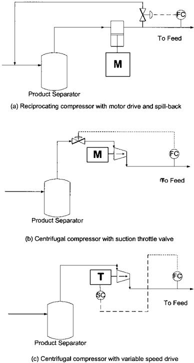
The driver for varying hydrogen recycle is its effect on coke production. Units in an unconstrained coke operation are run to a specified hydrogen-to- hydrocarbon ratio in an attempt to control the rate of coke laydown to an acceptable rate. Those units that are coke make-constrained maximize hydrogen
Table 2 Basic Regulatory Control: Typical Operating Variables
Control variables |
Manipulated variables |
|
|
Severity (usually RON) |
Heater outlet (reactor inlet) temperature |
Hydrogen recycle rate |
Recycle flow |
Feed rate |
Feed flow controller |
Heater excess air/firebox pressure |
Stack damper/air register position |
Reactor system pressure |
Product separator pressure |
Stabilizer pressure |
Stabilizer overhead receiver pressure |
Reformate RVP |
Stabilizer bottoms temperature |
Stabilizer overhead specification |
Stabilizer reflux flow controller |
|
|
Control Systems for Commercial Reformers |
503 |
recycle to the limits of the instrumentation or process equipment, with equipment constraints being the most common limit. The type of compressor and associated driver usually determines the instrumentation used for hydrogen recycle gas control. The three most common methods of instrumentation are shown in Figure 3. Depending on the design requirements, aspects of the various systems may be incorporated into an integrated design.
The reformer feed rate is usually specified by the refiner’s planning department [6]. To reduce the impact of moisture absorbed in stored feed on the catalyst, reformer feed control systems are designed to maximize feed coming directly from the hydrotreater and still be on flow control. If the bottom of the hydrotreater stripper is adequately sized, the flow to the reformer can be on flow control, and the surge volume of the hydrotreater stripper is maintained by adjusting the feed rate to the hydrotreater as shown in Figure 4a. In this configuration, all of the reformer feed comes directly from the hydrotreater. A common feed line-up is presented in Figure 4b. A small part of the treated naphtha from the hydrotreater goes to storage, the bulk goes to the reformer, and the reformer feed rate is maintained by a slip stream from storage. The reformer feed tank serves as a surge drum between the hydrotreater unit and the reformer.
Heater excess air and firebox pressure are controlled simultaneously with the air registers and the stack damper(s). Closed-loop controllers must be designed in such a manner that disturbances in the unit operation that (1) increase the firing rate are used as feedforwards to open the damper prior to additional fuel being added to the system, and those that (2) decrease the firing rate are not used as feedforwards to close the damper prior to the reduction in fuel rate [7]. The burner manufacturer specifies minimal excess air rates. Recommended control schemes for fired heater excess air and firebox pressure controls are outlined in API RP-560. In most regulatory control systems on catalytic reformers, the damper position and registrars are in open-loop control with the operators making the required adjustments to meet both operating objectives and safe operation. This is done with either manually operated devices such as a chain wheel drive on a damper or a hydraulic positioner.
The reactor system pressure is simply controlled by a pressure controller on the product separator or on the product separator vent line. The excess hydrogen produced in the dehydrogenation reactions is vented to fuel or, more commonly, to a hydrogen header. In most reformer complexes the product separator pressure is set by the design and cannot be varied significantly due to a combination of factors, including feed pump head, compressor constraint issues, valve and pipe sizes, relief valve settings, stabilizer pressure, and downstream unit pressures.
Product separator temperature is usually not directly controlled. Tight control of the product separator temperature is normally not critical to the unit operation or equipment safety. Some units have temperature controllers adjusting the fin fan speed or louver positions.
504 |
Turpin |
Figure 3 Recycle compressor instrumentation.

Control Systems for Commercial Reformers |
505 |
Figure 4 Reformer feed diagrams.
Stabilizer pressure is maintained using a traditional pressure controller venting the off gas either to fuel or to a light-ends recovery unit. Maintaining system pressure is critical to maintaining proper separation in the stabilizer between the designated light and heavy keys in the tower. In most reformer complexes the stabilizer pressure is set by the design and cannot be varied due to a combination of mechanical limits.
RVP is typically maintained by adjusting the bottoms temperature of the stabilizer tower and using laboratory feedback. The best point for temperature measurement to control RVP is approximately three trays from the bottom of the tower. The third tray also offers the best location for the temperature measurement used in an inferred RVP calculation.
The stabilizer reflux rate is typically set to meet one of four specifications:
(1) a defined reflux rate; (2) a reflux-to-distillate ratio (reflux-to-feed is occasionally specified); (3) the tower overhead temperature; or (4) a heavy key concentration in the overhead liquid. The control of a defined reflux rate is accomplished using a standard flow controller on the reflux line. Because the liquid distillate off the stabilizer overhead receiver is on level control, the calculated reflux ratio used in reflux-to-distillate control uses a weighted average distillate rate in the denominator. (The calculation of the reflux-to-feed ratio uses the same type of weighted average feed rate because the stabilizer feed is on level control from the product separator.) The use of reflux to control the tower overhead temperature is normally done by cascading the overhead temperature to
506 |
Turpin |
a reflux flow controller. Changes in feed composition or unit severity can cause the stabilizer overhead composition to vary to the degree that the tower overhead temperature cannot be maintained without wild swings in the reflux rate. It is recommended that tower overhead temperature control be integrated with some form of overhead liquid composition control. Control of the stabilizer liquid composition is secondary to control of the reformate RVP. Also, the lag time and TSS for changes in the stabilizer overhead liquid composition due to changes in reflux are beyond the capabilities of a PID controller. Controlling the heavy key in the stabilizer overhead liquid requires the use of on-line analsis or laboratory analysis for feedback, both of which have a delay in feedback to the control function. Because of these issues, an intermediate controller is used, and the heavy key composition specification is implemented subordinate to the reformate RVP specification. Typical intermediate controllers are reflux-to-distillate ratio or tower overhead temperature, both of which have been discussed. In either option, both the tower overhead and bottoms are ultimately on composition control, which is a difficult control problem given the number of degrees of freedom and their limited range of operation.
Auxiliary Control System
In addition to the fundamental process control system, there are a series of auxiliary control systems. These will vary from unit to unit depending on the plant mechanical configuration and process equipment used in the reformer design. The systems listed in Table 3 and discussed in this section are representative of the auxiliary control systems to control utilities or control process equipment systems. Each auxiliary control system may have a set of subsystems. For example, a waste heat boiler will have a regulatory control system for steam generation, and subsystems for injection of chemicals and boiler blowdown. Auxiliary control systems may also have their own safety systems, such as pressure relief systems.
Table 3 Example Auxiliary Control Systems
Waste heat boiler control system
Water/chloride injection system
Compressor lubrication system
Cooling tower acid/chlorine control system
Instrument air system
Fuel system

Control Systems for Commercial Reformers |
507 |
Heat to the reactor section of the reforming process is transferred in the radiant sections of the charge and interheaters. To increase the efficiency of the fired heater(s) a convection section is added with a convection duty coil for the stabilizer reboiler, an air preheater, a waste heat boiler, or some combination of these waste heat devices. The most common use of the convection heat is a waste heat boiler. A typical control strategy is shown in Figure 5.
The boiler feed water is made up to the steam drum on level control. The water-circulating loop maintains the flow at roughly five times the steam rate. The drum is on conventional pressure control. A superheater is shown in Figure 5 and may have a quench. Control of water quality is done with standard wet laboratory quantitative laboratory tests. Chemical injection and blowdown rates are adjusted manually based on routine test results and changes in rate of steam production.
The catalyst acidity is maintained by injection of water (or a compound that converts to water in the reformer environment) and an organic chloride-bearing compound that will release the chloride on the catalyst. The water and chloride agent are injected into the reactor system in very small quantities using small chemical injection pumps. These are typically plunger pumps with self-contained regulators that permit the operators to set a specified injection rate. Some of the regulators allow the settings to be adjusted through a DCS system.
Compressor lubrication systems are self-contained oil systems with a circulation pump, filters, and associated flow control devices. Subsystems include pressure relief systems and alarms systems. Signals to the emergency shutdown
Figure 5 Typical waste heat boiler controls.
508 |
Turpin |
system are included to shut down the compressor upon failure of the lubrication system.
The water quality in a cooling tower system is primarily maintained by injecting acid and chlorine. On-line analyzers are used to maintain pH, conductivity, and dispersions by regulating the quantity of acid and dispersant injected into the system and blowdown rate. The dead time and TSS are sufficiently long so that conventional PID control is not suitable for this application. Control systems are used that are specifically designed to handle cooling water chemistry and operate in the severe atmosphere around a cooling tower. These are usually programmable logic controllers (PLCs) installed at the cooling tower, which receive input from the analyzers and send output signals to regulatory valves and chemical injection pump flow controllers.
Instrument air systems are often located in process units or situated between units in close proximity to one another. Plant air is passed through a dryer and then reduced in pressure to approximately 30 psig. Instrumentation on the plant air system usually consists of a pressure controller sized to take wide swings in load and still maintain a stable air system pressure throughout the process unit. In some cases moisture analyzers are included in the system design. Most instrument air systems have a primary air source and a secondary air source to provide air in the situation where there has been a failure in the primary air source. This normally includes a second pressure regulator with its setpoint slightly below the primary regulator setpoint. The difference in settings must be large enough to provide for normal fluctuations in the air supply pressure.
The fuel system in a reformer unit normally consists of two or more independent systems. One system is the pilot gas system, which is maintained on pressure control. Normally the pilot gas system is natural gas from an uninterruptable source. If the pilot gas can contain condensable compounds, a knockout drum with level control will be included in the unit instrument package. Reformer heaters fire gas, oil, or both. A unit fuel gas system consists of a knockout pot with level control on condensed liquids and pressure control on the fuel gas going to the heaters. In both the pilot gas and fuel gas systems, blowout instrumentation is provided in the control structure to prevent a depressurizing of gas into the liquid recovery system upon loss in liquid level. If a fuel oil system is also included in the unit design, there will be a fuel oil system with an associated atomizing steam system. The instrumentation on the atomizing steam system will be a pressure controller reducing steam down from a higher pressure saturated steam header, along with knockout drums or steam traps to keep the system from accumulating condensed water. The fuel oil system will include a level controller to maintain a stored quantity of fuel oil on site, a pressure controller to maintain pressure control on the system, and a flow controller to maintain a circulating oil supply. Quite often the circulating oil flow is controlled simply by having a restriction orifice (RO) in the fuel oil return line. Figure 6 shows the controls on

Control Systems for Commercial Reformers |
509 |
Figure 6 Fuel system controls.
an integrated fuel system. The process controllers have been omitted from the drawing for clarity. Significant control problems can exist in an operation where both fuel oil and fuel gas are being simultaneously fired to maintain a process temperature setpoint. The dynamic response to changes in the firing systems between fuel gas and fuel oil are appreciably different. One controller cannot be used for both services with adequate responsiveness. If the operation is going to switch between fuel oil and fuel gas, two separate controllers need to be utilized. The same primary sensor element can be used, but the controllers must be different. If both fuels are to be fired simultaneously, one fuel should be base loaded and the second used for control of the process temperature. Base loading oil and controlling with fuel gas is viewed by most operating companies as the preferred operation. Fuel availability issues may dictate that the fuel gas be base loaded and the fuel oil used to control the setpoint.
2.3.Emergency Shutdown Systems
The control system on a catalytic reformer that handles the shutdown of the equipment and blocking in of hydrocarbon lines in the case of catastrophic failure or when a piece of equipment has exceeded a safe limit of operation is known as the emergency shutdown system. Emergency shutdown systems are designed to minimize damage to process equipment and protect personnel; they are not used for equipment shutdown in the normal course of operation, only in emergencies. The basic emergency shutdown system is a logic system that sets a sequence of actions into place when one of a number of causes, called “initiating events,” activate the system via an “initiation event signal.” The resulting action(s) are triggered by “initiation response signals” generated by the emergency shutdown system. This is handled using a logic tree, with an operator-initiated emergency shutdown as one of the initiating actions. The other initiating branches in the
510 |
Turpin |
logic tree are a series of equipment failures. Typically each event-initiating device sends a positive initiation event signal to the emergency shutdown system during normal operation. When that signal is lost or goes negative, a series of shutdown actions are instigated via initiation response signals from the emergency shutdown system [8].
Emergency shutdown systems frequently have functionality added to the automated shutdown logic for maintenance, testing, and repair. Added functionality includes logic for startup bypasses, initiation event signal bypasses, and response signal bypasses. Startup bypasses allow the sections of the emergency shutdown system to be disabled while equipment is being brought online. Initiation event signal bypasses cut off the signal from the various initiation event generators and send a false positive (normal operation signal) initiating event signal to the emergency shutdown logic. This allows instrumentation to be repaired without shutting down the unit. The response signal bypasses block an event-generated output signal so that testing and maintenance can be performed on various pieces of equipment, including the emergency shutdown system [9].
Emergency Shutdown System—Initiating Events
Initiating events come from three sources. The first initiating event is an operatorinitiated event. An operator initiates the shutdown system in one of two cases. The first case would be when a system failure has occurred outside of the planned instrumentation. An example is processor utility line rupture. A second case in which an operator would initiate the emergency shutdown system is when there has been an instrument failure and the emergency shutdown system failed to respond to an initiating event.
The second initiating event is failure of a piece of equipment or a supporting system. For example, the feed pump to the unit may shut down due to a bearings failure. The feed flow would go to zero and the shutdown system would be initiated. An example of a piece of equipment failing due to a supporting system is a recycle compressor shutdown due to the failure of a lubricating pump. The recycle flow would go to zero and the shutdown system would be initiated.
The third source of an initiating event is the loss of a utility system such as fuel gas, steam, instrument air, or electricity.
Logic Tree for a Catalytic Reformer Emergency Shutdown System
Emergency shutdown systems can range from a simple series of integrated switches to extremely complex logic functions. As the sophistication of instrumentation and the use of computers, DCSs, and PLCs have become more prevalent, the emergency shutdown systems have become more complex. One of
Control Systems for Commercial Reformers |
|
|
511 |
||
Table 4 Sample Emergency Shutdown Response Matrix |
|
|
|||
|
|
||||
|
Response actions. Check indicates response |
||||
|
|
|
|
|
|
|
Cut fuel |
Close |
Shut down |
Shut valve |
Shut net |
|
to |
feed |
recycle |
to |
hydrogen |
Event initiators |
heaters |
valve |
compressor |
stabilizer |
valve |
|
|
|
|
|
|
Operator initiated |
3 |
3 |
3 |
3 |
3 |
Feed pump shutdown |
3 |
|
|
|
|
Recycle compressor shutdown |
3 |
3 |
|
|
|
Electric power failure |
3 |
3 |
|
3 |
3 |
|
|
|
|
|
|
the most easily understood shutdown logic systems is a shutdown matrix as shown in Table 4. This emergency shutdown response matrix is abbreviated for demonstration. The event initiators are listed on one axis and the resulting actions listed on the other.
Complex Boolean logic diagrams are sometimes prepared for catalytic reformers. The complex logic diagram methodology increases the flexibility of the system. For example, if two initiation events happen simultaneously, the resulting set of responses may be different from the sum of the two responses designated in a response matrix [9].
Emergency Shutdown System and Overall Plant Safety
Design and implementation of emergency shutdown systems are regulated by governments, industry groups, instrument and safety societies, or company policies as part of a process safety management program. Life cycle management programs often require multidisciplined reviews and associated record keeping of the initial installation of control systems and all subsequent modifications. Regulations often include requirements of multilayered control and safety systems that can each function independently of one another yet work together to form an integrated system. Layered safety systems within the reformer process area are often extended beyond the battery limits to incorporate the reformer operations and safety systems as part of an extended plant safety system [8].
2.4.Process Equipment Safety Systems
Each piece of process equipment has at least one safety system associated with its operation designed to protect equipment and the personnel who operate the process units. The mechanical design of the equipment, type of equipment, and
512 |
Turpin |
company safety policies dictate the systems to be used in a particular reforming unit. The equipment safety systems may or may not be event-initiating devices in the emergency shutdown system.
Fired Heaters
Fired heaters are typically instrumented with at least three different safety systems. One is a shutoff on the fuel system if there is a disruption to the fuel flow—typically triggered by a low flow measurement device. A second safety system is a shutoff of the fuel system if the flame goes out in the heater. Instruments located in the heater detect the presence of flame via light intensity. The third common safety system is low oxygen content in the flue gas stack or the flue gas in the transition zone between the radiant and convection sections of the heater. Upon the measurement of low oxygen content in the flue gas, the burner louvers and/or stack damper are opened to increase the oxygen entering the heater. In addition to directly measured safety variables, such as temperature and oxygen content, calculated tube skin temperatures and flux rates are used as operating constraints [10].
Recycle Compressor and Drivers
Centrifugal recycle compressors are typically instrumented with surge control systems. When applicable, a kickback valve will be opened to move the operation away from a potential surge in the compressor. Electric motor drivers are monitored for overamperage operation through time. The electrical switch gear will break the electric supply to the motor before the motor coils or windings exceed a specified temperature. Steam turbine drivers are installed with govenors.
Pressure Relief System
In a catalytic reformer, all of the piping and equipment is protected by pressure relief systems from uncontrolled process fluid expansion due to a heat source, chemical reaction, or mechanical compression. Typically these are relief valves, but they can be rupture disks, or a combination of both rupture disks and relief valves. The vessels and piping are divided into operating zones such that any area of pipe and vessels that can be blocked in and are subject to a process fluid expansion are protected by a pressure relief system.
2.5.Catalyst Control Functions
Control of the reformer catalyst is centered around two areas. The first is the catalyst environment—the managing of the chloride level and its distribution on
Control Systems for Commercial Reformers |
513 |
the catalyst. The second area of catalyst control is management of the catalyst deactivation. Several performance indicators are calculated either by engineering staffs or automated systems to aid in monitoring and controlling performance of reformer catalyst.
Catalytic Reformer Performance Indicators
The following performance indicators are calculated on a scheduled or as-needed basis. These performance indicators are used in monitoring the process unit and in some cases are used as control variables in APC applications [12].
WAIT—weighted average inlet temperature ¼ S(Ti RXWTi) Ti ¼ inlet temperature to reactor (i)
RXWTi ¼ weight of catalyst in reactor (i)
Adjusted WAIT—WAIT adjusted to base operating conditions ABT—average bed temperature ¼ T d(L), L ¼ 0–1
T ¼ temperature of catalyst at distance L through the catalyst bed L ¼ fraction of the distance through the catalyst bed in the direction of
hydrocarbon flow
WABT—weighted average bed temperature ¼ S(ABTi RXWTi) ABTi ¼ average bed temperature of reactor (i)
RXWTi ¼ weight of catalyst in reactor (i) LHSV—liquid hourly space velocity WHSV—weight hourly space velocity
H2/HC—hydrogen-to-hydrogen ratio ¼ mole H2 recycle/mole feed C1 molar ratio, C2 molar ratio, C3 molar ratio
C4 isomer ratio ¼ iC4/nC4
Aromatics production as weight percent of feed
Aromatics as a weight (or volume) percent of reformate (or C5þ) MCP (methylcyclopentane) conversion ¼ 100 (MCPIN2MCPOUT)/
MCPIN
MCPIN ¼ moles of MCP in the feed
MCPOUT ¼ moles of MCP in the net reaction products Paraffin disappearance ¼ 100 (PARAIN2PARAOUT)/PARAIN
PARAIN ¼ moles of C5þ paraffin in the feed
PARAOUT ¼ moles of C5þ paraffin net reaction products Aromatics selectivity ¼ 100 paraffin converted to aromatics/paraffin
disappearance
RON (research octane number) RVP (Reid vapor pressure)
514 |
Turpin |
Catalyst Environment
The catalyst environment refers to quantity and distribution of chloride on the catalyst and the amount of water in the system. Because chloride and water leave the unit with the reaction products, small quantities are injected to maintain the prescribed water/chloride balance. In many units catalyst samples are taken to monitor the chloride content, and in some systems correlations of the methane, ethane, and propane molar ratios are used for feedback in the control of the catalyst environment. Moisture analyzers are normally installed to measure the water content of the recycle gas to (1) provide feedback to the calculated recycle gas moisture content and (2) signal if the water content of the feed has varied [3].
Catalyst Deactivation
Catalyst deactivation is primarily a function of coke deposition on the catalyst. The catalyst poisons other than coke are managed through proper operation of the preceding naphtha hydrotreater. Controlling coke deposition is equivalent to controlling catalyst deactivation. Several methods of tracking the deactivation are employed, but all serve the same objective: to anticipate unit performance by monitoring past and present operation. In many units, two key variables are tracked: coke laydown rate (coke deposition per unit time) and weight percent carbon on catalyst. In a continuous catalyst regeneration (CCR) operation the coke on catalyst must be maintained at a level to maintain reasonable activity and proper regenerator performance. In a semiregenerative reformer operation the objective in catalyst activity management is to end a cycle of several months of operation with a specified weight percent coke on catalyst. The coke on the catalyst through a cycle follows an exponential rate of deposition. Controlling the coke laydown rate by adjustment of feed rate, feed composition, hydrogen recycle, and severity allows a processor to proceed through a cycle at a planned WAIT through the cycle. Chapters 10 and 11 discuss coking in more detail.
3ADVANCED PROCESS CONTROL OF CATALYTIC REFORMERS
Modern APC systems use one or more multivariable controllers to control the operation of a catalytic reformer. APC assists in the control of a reformer in two areas of the operator’s standard duties. First, APC adjusts the basic regulatory controllers to meet a set of operator-entered processing objectives, and second, APC monitors the unit operation and makes adjustments as needed for disturbances in the unit operation. Unlike an operator, APC applications are normally proactive and start adjustment of control variables at the time of the disturbance, before changes in measured variables can be recognized [4].
Control Systems for Commercial Reformers |
515 |
There are three fundamental differences between the way an operator performs and the way an APC application works in a catalytic reformer. First, APC applications may be used to process delayed feedback (long lag times) from process instruments and long intervals to steady state (long TSS) on a model predictive basis. However, operators need to wait well past the lag time to analyze the impact of the disturbance on the process before taking an action. Second, operators tend to make a series of directionally correct changes with necessary time intervals for the process to come to steady state, for sample collection, and for sample analysis, and eventually arrive at an appropriate operating condition. An APC application makes a more precise move in its first step; then it starts making adjustments as soon as feedback can be detected rather than waiting for the unit to come to steady state. On-line analyzers or inferred properties are used for feedback when a process variable cannot be measured directly with traditional temperature, pressure, and flow instrumentation. The third difference between an operator and APC is the way overlapping constraints are handled. An APC application recognizes at the initial time of the operator entering the new target whether or not there will be multiple constraint/target conflicts and resolves them at the time of first move of the independent variable. In some cases, multiple independent variables may be moved to resolve the processing conflicts.
APC can only manipulate those variables that are in closed-loop control under the APC system. Operators must bridge the control gap when a system is open loop. For example, if the cooling water temperature starts to increase, the flash drum temperature may increase. This in turn results in a higher molecular weight of the recycle hydrogen gas, which may cause the recycle compressor to bump a driver limit. The only solution available to the APC system may be to reduce charge rate. However, the operator may have another option, such as turning on another fan in the cooling tower.
An APC application works with three kinds of variables: manipulated variables (MVs), control variables (CVs), and feedforward variables (FFs). In general terms, the multivariable controller maintains the operation of the reformer at multiple CVs. All MVs in an APC application are variables with closed-loop control in the regulatory control system, usually temperature, flow, and pressure controllers. The CVs are most often measured variables such as instrument readings and analyzer output, but can also include calculated performance indicators or inferred properties. Table 5 is a list of the common MVs, CVs, and FFs found in a catalytic reformer APC application.
3.1.Instrumentation Requirements for APC
The instrument requirements for implementation of APC in a catalytic reformer are typically the same as for basic regulatory control. APC can control a reformer
516 |
|
Turpin |
Table 5 APC Variables List |
|
|
|
|
|
Variable description |
Type |
Notes |
|
|
|
Manipulated Variables |
|
|
Feed rate |
SP |
|
Recycle compressor turbine speed |
SP |
|
Charge heater outlet temp. |
SP |
|
Interheater 1 outlet temp. |
SP |
|
Interheater 2 outlet temp. |
SP |
|
Interheater 3 outlet temp. |
SP |
|
Product separator pressure |
SP |
|
Heater burners—primary air louver position |
SP |
|
Stabilizer feed temp. |
SP |
|
Stabilizer reflux rate |
SP |
|
Stabilizer tray 26 liquid temp. |
SP |
|
Feedforward Variables |
|
|
Cooling water temp. |
PV |
|
Control Variables |
|
|
Reformate RON |
PV |
Inferred Property |
C5þ in stabilizer overhead liquid |
PV |
GC |
Reformate RVP |
PV |
Inferred Property |
Weighted average bed temp. (WABT) |
PV |
Calculated |
Hydrogen-to-hydrocarbon ratio (H2HC) |
PV |
Calculated |
Heater box pressure |
PV |
|
Charge heater tube skin temp. |
PV |
Inferred |
Interheater 1 tube skin temp. |
PV |
Inferred |
Interheater 2 tube skin temp. |
PV |
Inferred |
Interheater 3 tube skin temp. |
PV |
Inferred |
Stabilizer reflux ratio |
PV |
Calculated |
Heater excess air |
PV |
Calculated |
Net gas valve position |
PV |
|
|
|
|
SP, setpoint; PV, process variable.
operation more precisely than human beings, but human beings can handle poorly tuned controllers, open-loop control, and discontinuous operations.
The degrees of freedom for each unit operation must be analyzed to ensure that the problem is not overspecified and yet is completely specified. It is recommended that a pairing chart be constructed to assure that each CV has a valid function, and that each CV has at least one associated MV which when moved will significantly impact the magnitude of the value of the CV. If the number of CVs exceeds the number of MVs, all of the CVs will probably not be
Control Systems for Commercial Reformers |
517 |
solved exactly. For example, if the steam rate to the stabilizer reboiler is the MV, and the bottoms temperature is a CV (process operating target) and the steam valve position is a second CV (mechanical constraint), when the bottoms temperature specification is solved (exactly) by adjusting the steam flow rate, the steam valve position will be less than its mechanical constraint (not exactly at limit). To solve the problem of multiple CVs without direct solutions, typically a linear program is included in the multivariable controller to maximize a profit function.
The multivariable controller on a reformer unit must have each contributing MV and disturbance variable properly associated with the CVs. Table 6 is a sample theoretical pairings matrix relating typical and contributing MVs and FF (disturbance variables) to the CVs of a catalytic reformer APC application. Plant tests performed at the beginning of an APC implementation project determine the actual pairing with the CVs in the controller. Basic regulatory controls must be properly paired with the correct feedback variable. If the CV does not have a paired MV that can move the control variable over the anticipated operating range, the function cannot be implemented in an APC application.
Instruments must not display hysteresis. Hysteresis is a control problem where the output from an instrument is not consistent, both in response times and in magnitude for a specific change of input, or does not give a mirror image in magnitude of response when the input is reversed. An example of hysteresis is a stack damper with positioner input signal ‘X’ for position ‘A’. The input signal is changed from ‘X’ to ‘Y’ and the damper moves from position ‘A’ to ‘B’. But when input signal X is reapplied, the damper moves to position ‘C’ rather than back to position ‘A’.
3.2.APC Application in the Reactor Section
Advanced process control in the reactor section of a catalytic reformer is centered on (1) maintaining a target operating severity in the process, (2) controlling catalyst deactivation, and (3) controlling the fired heaters. In a reformer with continuous catalyst circulation, a fourth area is controlling the coke loading on the catalyst to meet the regenerator burn requirements [13], and will be covered in Section 3.4.
Reformer Severity Control with APC
Traditional reformer severity control in gasoline operations and many chemical operations is based on RON. Other severity targets, such as aromatics make, are frequently used in chemicals operations. RON and the alternative severity definitions are primarily basic expressions of conversion of paraffins to

518
Table 6 Example MV and CV Pairings Matrix
MVs and FFs
|
|
Comp. |
Chg. htr. |
Heater 1 |
Heater 2 |
Heater 3 |
Prod. |
Burner |
Stab. |
Stab. |
Stab. tray |
|
Feed |
turbine |
outlet |
outlet |
outlet |
outlet |
sep. |
louver |
feed |
reflux |
26 liq. |
CVs |
rate |
speed |
temp. |
temp. |
temp. |
temp. |
pressure |
position |
temp. |
rate |
temp. |
|
|
|
|
|
|
|
|
|
|
|
|
Reformate RON |
3 |
3 |
3 |
3 |
3 |
3 |
3 |
|
|
|
|
C5 þ in stab. OH |
3 |
|
3 |
3 |
3 |
3 |
3 |
|
3 |
3 |
3 |
Reformate RVP |
3 |
|
3 |
3 |
3 |
3 |
3 |
|
3 |
3 |
3 |
Wt. avg. bed temp. |
3 |
3 |
3 |
3 |
3 |
3 |
|
|
|
|
|
H2HC ratio |
3 |
3 |
|
|
|
|
3 |
|
|
|
|
Heater box pres. |
3 |
3 |
3 |
3 |
3 |
3 |
|
3 |
|
|
|
Charge htr. TST |
3 |
3 |
3 |
3 |
3 |
3 |
|
3 |
|
|
|
Heater 1 TST |
3 |
3 |
3 |
3 |
3 |
3 |
|
3 |
|
|
|
Heater 2 TST |
3 |
3 |
3 |
3 |
3 |
3 |
|
3 |
|
|
|
Heater 3 TST |
3 |
3 |
3 |
3 |
3 |
3 |
|
3 |
|
|
|
Stab. ref. ratio |
3 |
|
|
|
|
|
|
|
3 |
3 |
3 |
Heater excess air |
3 |
3 |
3 |
3 |
3 |
3 |
|
3 |
|
|
|
Net gas valve pos. |
3 |
3 |
3 |
3 |
3 |
3 |
3 |
|
|
|
|
|
|
|
|
|
|
|
|
|
|
|
|
Turpin
Control Systems for Commercial Reformers |
519 |
aromatics, which is driven by reactor temperature. In a modern APC application the CV severity can be measured or inferred and the reactor inlet temperature MVs specified directly.
Reformer Catalyst Deactivation Control with APC
Catalyst deactivation is a result of poisons in the feed and coke laydown due to unit upsets, feed composition, temperature, and hydrogen partial pressure. APC applications can be designed to handle all of these factors except unit upsets. Hydrogen partial pressure is normally adjusted by changing the hydrogen recycle rate as opposed to changing system pressure. Very few commercial reformers have been built with the capability of making significant shifts in unit pressure. In the simplest of APC applications, the hydrogen-to-hydrocarbon ratio is maintained.
In more sophisticated applications, the APC controls to a maximal coke laydown rate in mass per unit time. Figure 7a shows an idealized plot of coke deposition over a catalyst cycle. The slope of the plot at any point in time can then be taken as the coke laydown constraint in the APC application. However, the planned coke deposition plot and reality rarely match. Unplanned poisons in the feed, or unit upsets and other factors create variations in the planned operation. To account for these factors, the coke deposition plot must be updated through the cycle using either measured coke or inferred coke deposition. Some reactor sections have catalyst samplers that can be used to sample the catalyst and permit measurement of the coke. An alternative is to generate a coke vs. adjusted WAIT plot. Figure 7b is a representative plot of coke vs. temperature. As the adjusted WAIT requirement increases through the cycle, the coke deposition plot can be reconstructed to provide new coke laydown constraints.
APC of Reformer Fired Heaters
Firebox management describes the strategies that (1) provide the correct amount of heat to meet processing objectives, such that (2) heat loss to the environment is minimized, and is done in a manner that is (3) safe for workers and maintains equipment integrity. APC regulatory controls must be integrated in such a way as to provide stability and flexibility. Heat loss is a function of mechanical design, maintenance, and the excess air provided for combustion. The latter is the only parameter that can be affected by heater controls.
There are several aspects of fired heater safety. In the domain of control, this means providing mechanisms that prevent explosive mixtures from being formed in the firebox and both general and localized overfiring. Maintaining the burner vendor-prescribed excess air will ensure that all fuel is burned in the

520 |
Turpin |
Figure 7 Coke deposition plots.
combustion zone of the burner and the resultant flame pattern is compatible with the firebox configuration. It is also necessary to maintain the correct pressure (draft) balance in a fired heater to ensure correct air/fuel mixing in the burner and to minimize air leakage through the heater walls.
Control Systems for Commercial Reformers |
521 |
3.3.APC Application in the Separation Section
In the application of APC to catalytic reformer units, the area that is typically underspecified is the stabilizer operation. Sufficient degrees of freedom typically exist to allow for two tower specifications, one on the top operation and one on the reformate. Common tower top specifications include (1) total C5þ in the overhead liquid, (2) benzene in the overhead liquid, or (3) reflux ratio. The composition specifications require either an on-line analyzer or use of an inferred property for feedback. Because of the concentrations being specified, the inferred properties are considered adequate for most operations but not precise. Inferred properties have the advantage over on-line analyzers because of reduced lag time in feedback. A calculated value is nearly instantaneous and continuous. In contrast, the output signal from an on-line gas chromatograph is incremental, typically with a 5- to 10-min gap in feedback results. To overcome this problem even when on-line analyzers are available, inferred properties are used with the analyzer providing frequent updates. This also allows the APC application to remain in operation when the analyzer fails or is down for routine maintenance. The specification on the reformate for most commercial applications is either RVP or a specific component concentration.
3.4.APC Special Case Applications
Coke Handling
In a continuous catalyst circulation reformer operation, the catalyst circulation rate can be adjusted to maintain a specified weight percent carbon on catalyst. The lag time in the response of the coke on catalyst to changes in unit operations, including changes in catalyst circulation rate, is very long. The ratio of lag time of the coke on catalyst to the next slowest variable is roughly 100 : 1 or twice the maximum recommended for an APC application. Sophisticated interlocking controllers are used to handle this problem. To implement a coke on catalyst controller, the system must be installed with a coke laydown rate calculation package. The more important the need to accurately control the coke on catalyst, the higher the requirement for an accurate coke deposition calculation package. When APC is to be utilized to operate the reformer against a regenerator coke burn constraint, very precise coke calculation is required.
Catalyst Regeneration
Catalyst regeneration systems in both cyclic units and continuous catalyst circulation units are typically controlled with PLCs. Changing the control of the catalyst regeneration to an APC application is not needed. However, using a
522 |
Turpin |
small APC application installed in parallel to the PLC application may improve the regenerator performance at a very low capital investment.
Integrated Feed Systems
Reformer APC systems often have integrated feed systems. One type of integrated feed system is a unit with a base feed and a supplemental feed. The APC application adjusts the supplemental feed to a constraint. Typical supplemental feed constraints are coke laydown rate, maximal supplemental feed rate, maximal total feed rate, LHSV, and catalyst pinning. The second type of integrated feed system is the reformer unit with feed coming directly from the hydrotreating unit, and the feed rate to the hydrotreating unit is adjusted to maintain the charge rate to the reformer. Traditional PI controllers do not work well in these applications; heavy operator involvement is almost always required. This is a very simple problem for an APC application.
Minimization of System Pressure
The system pressure in a reformer can be minimized with an APC application. The economic driver for this is increased C5þ yield at constant severity. There are several constraints that must be evaluated in commercial units. First, the hydrogen must be able to leave the unit. The typical constraint used in APC is the product separator pressure control valve position. To facilitate operation, the control valve trim needs to be checked to ensure tight pressure control when operating at the end of the valve curve. The second common constraint is coke make. If pressure is going to be minimized, a coke laydown rate constraint or pressure compensated hydrogen-to-hydrocarbon ratio must be used.
3.5.Inferred Properties
Inferred properties can be generated with a number of math tools ranging from simple regressions to neural networks and artificial intelligence tool kits. In all situations it is essential that process measurements be transformed to appropriate format for use in the calculation package. A simple example is the use of pressure-compensated temperature to infer the concentration of C5þ in the stabilizer tower overhead. In many cases, an analyzer measuring one stream property can be used to infer a second stream property. For example, hydrogen purity of the recycle gas can be easily inferred from the recycle gas gravity, which is an easy and inexpensive on-line measurement. In some instances it is critical that first-principle calculations be used to calculate inferred properties. Common regression and neural network inferential tool packages can generate calculations that work well over the base set of data used for the development and work for
Control Systems for Commercial Reformers |
523 |
several sets of test data, but then fail during routine application on a live process unit.
When analyzers are used for controlling the process, it is common practice to use an inferred property to control the process and have the analyzer update the inferred property package. This allows an analyzer with long delays between executions to be used in an APC application, which is better served with nearinstantaneous feedback from the process. Use of a combined analyzer and inferred property package also allows the controller to continue operating if the analyzer is taken out of service for routine maintenance or fails due to a mechanical problem.
In the development of inferred properties, the engineer designing the calculation must take into consideration the characterization [11] (random or systematic) and the magnitude of the errors of the measured values being used in the calculation. The calculated expected error of the inferred property should not be more than one and a half times the direct measurement reproducibility of the inferred variable. The following summaries provide guidelines on proven methodologies for inferring various properties for catalytic reformer applications.
Research Octane Number
RON can be inferred from reactor temperatures, feed rate, recycle rate, and feed properties. It is important to update the inferred RON as catalyst activity changes, or have a function incorporated into the inferential that allows for changes in catalyst activity. One method of obtaining this information is from plant tests, which are expensive, have low reproducibility, are often limited in range of variable operation, and can rarely be done at constant catalyst activity. A second method of obtaining inferential data for RON is to use correlations developed by catalyst vendors, research centers, or other sources of large volumes of reformer operating data. The effects developed from this data will at least be directionally correct and will be close to the right magnitude if the unit for which the inferred RON calculation has an operation similar to the average of the collected data. The preferred method for determining a RON correlation is to exercise a kinetic model through the range of operation of the variables to be included in the calculation.
Reid Vapor Pressure
The inferential calculation of RVP is usually based on a modification of the Clausius–Clapeyron equation [14]. This is applicable because the vapor pressure of reformate is low and it can be assumed that the light hydrocarbons in the reformate obey the ideal gas law. These inferentials work well when the RVP is in the range of 5–10 psia, which is a common operation for most reformers. To
524 |
Turpin |
obtain good results, the stabilizer bottom pressure must be measured rather than calculated from a top pressure and assumed pressure drop across the tower. The temperature used must be representative of the equilibrium tower bottom liquid temperature.
Stabilizer Overhead Composition
Preparing a robust inferential calculation for a component in the stabilizer overhead liquid is nearly impossible in a dynamic operating environment. The typical approach is to infer the C5þ content of the stream using tower temperature and pressure measurements. A gross regression of operating data and laboratory measurements can be used. A slightly more rigorous approach can be used by assuming a vapor pressure for the C42, a second vapor pressure for the C5þ, and calculating the concentrations required to meet the process temperature and pressure. Both methods are restricted due to changes in C42 concentration due to changes in feed composition, operating severity in the reactor system, and chloride level on the catalyst.
Feed Composition from Density
The P (paraffin), N (naphthene), and A (aromatic) distribution can be inferred from a gravity measurement. On-line liquid gravity (density) analyzers are inexpensive, have a low maintenance cost, and give a continuous analysis signal to the control system. Properly installed, the lag time is relatively small. The calculation is done by assuming a constant N/A ratio, a bulk P gravity, bulk N gravity, and bulk A gravity. From the N/A ratio a bulk NA gravity can be calculated. With a given measured gravity, the concentration of P and NA can be calculated. From the calculated NA concentration and assumed N/A ratio the N and A concentrations can be calculated. The Nþ2A or Nþ3A feed descriptors can then be calculated. This technique is restricted to operations with limited variations in feed distillation range and feeds with roughly the same N/A ratio.
Coke Laydown Rate
Coke laydown rate is a function of the coke precursors in the feed, hydrogen partial pressure, space velocity, and temperature. As with most inferentials, an equation for coke laydown rate can be regressed from operating data taken over an extended period of time and a broad range of operating conditions. Each of the variables used in the correlation must be varied over the anticipated operating range. A second way of developing a coke laydown rate equation is to use basic kinetic terms. These need to be simplified to keep the number of calculations to a minimum and the processor utilization to an acceptable level. Activation energies
Control Systems for Commercial Reformers |
525 |
and frequency factor data can be obtained from pilot plant runs or literature sources [15].
Fired Heater Tubeskin Temperatures
Fired heater tubeskin temperatures can be calculated from basic radiant heat transfer equations [16]. Although the primary heat transfer mechanism is radiant heat, a small percentage of convective heat can be assumed. This can be determined from field tests. Heater-specific mechanical configuration data should be used to calculate the radiant section cold-plane effectiveness and cold-plane area. The heat transfer coefficient can be calculated for the tube walls. An effective firebox temperature can be calculated on-line from the bridgewall temperature using a bias. The flux rates used in the tubeskin temperature computation can be calculated from fireside and process data [10]. The inferred tubeskin temperatures need to be updated from measured values. Measurement is usually made with either tubeskin thermocouples or an optical pyrometer. There are three critical areas in the calculation. First is developing the thin wall resistance of the internal fluid in the tubes; the second is estimating any change in resistance on the external surface of the tubes; and the third is measurement of the bridgewall temperature. The bridgewall temperature measurement in most commercial heaters is done with a thermocouple dropped through the ceiling of the heater. The use of a shielded, high-velocity thermocouple is preferred.
Recycle H2 Purity
Recycle gas hydrogen purity can be inferred from online recycle gas density measurement. A simple regression can be used. As with all analyzer-based inferentials, the inferred property validity should be a function of the analyzer signal validity.
3.6.On-line Analyzers
Recycle Hydrogen Purity Analyzers
Two types of analyzers are used for on-line measurement of recycle gas hydrogen purity. In some instances, on-line gas chromatographs are used. These analyzers also provide a composition analysis of the entire stream with the exception of trace compounds. Most refiners use an on-line density analyzer with inferential calculation to convert gravity to hydrogen concentration.
526 |
Turpin |
Recycle Hydrogen Moisture Analyzers
Two types of moisture analyzers are in common use for measuring the moisture content in the hydrogen recycle gas [17]. One analyzer uses an in situ probe with an aluminum oxide sensor. Because these analyzers are in situ installations, they cannot be calibrated on-line. Analyzer drift can be a problem. The second type of analyzer is an extractive analyzer that is based on the change in vibrational frequency of a hydroscopically sensitized quartz crystal as the moisture content of the stream varies. Because moisture analyzers are not used for direct process control, a lag time of several minutes is of no consequence.
Reformate Octane Analyzers
Several different technologies have been used to generate a RON measurement for the reformate [17]. One technology is to use an ASTM/CFR engine configured for continuous service. The analysis is not instantaneous, and a lag time is built into the system with the sample collection and preparation system. These analyzers have a tendency to drift and have a high downtime factor for routine maintenance. This method is the only direct on-line measurement of octane.
Delta knock analyzers have been developed for on-stream octane analysis. The difference in knock index is determined between the sample and a base material. The difference is then added to the known base material octane. The analysis is incremental with added lag times for stream sampling and preparation. Significant maintenance is required.
Four other technologies have been developed in which secondary properties are measured and then octane inferred from these properties:
Gas chromatographs are used to first measure the composition of the reformate, and the octane is calculated using octane blending factors for each component. The lag time for analysis in this method is long.
Near-infrared (NIR) analyzers are based on light passed through the process fluid [18]. The analyzers have a fast response time, high reliability, multiple component monitoring, multiple sample point analyses, and very high on-stream times. However, calibration can be difficult.
A flame peak displacement analyzer monitors the reactions that are precursors to knock. Octane can then be inferred from the peak displacement of a sample fluid as compared to a standard fluid.
A technology utilizing a thermal oxidation reaction of the reformate infers octane by simulating the reactions in a knock engine. The sample analysis is incremental.
Control Systems for Commercial Reformers |
527 |
In modern installations, the preponderance of installed octane analyzers will be NIR-based analyzers. Specific technology and hardware is available from a number of vendors around the world. The instantaneous and reliable analyses make these analyzers good tools for APC applications.
Stabilizer Component Analyzers
Online gas chromatographs are the primary type of analyzer used for component analysis of the stabilizer overhead liquid. The samples are intermittent, and there is a significant lag time (typically in the 10-min range) between when the sample is taken and the results reported. NIR analyzers can also be used for component analysis of the stabilizer overhead liquid.
Reformer Feed Analyzers
Reformer feed analysis is primarily handled by on-line gas chromatographs. NIR analyzers could be used. As discussed in the feed inferential section, density analyzers can be used to generate bulk paraffin, naphthene, and aromatic concentrations of the feed. The gas chromatograph results are valuable information in real-time optimization of a commercial reformer operation. However, the results significantly lag the process and will not suffice for feed disturbance measurement.
Fired Heater O2 Analyzers
The oxygen content of the flue gas from fired heaters is measured with two different types of analyzers: extractive and in situ [17]. The in situ analyzer uses a zirconia oxygen sensor situated in a probe inserted into the fired heater. The signals are continuous, near-instantaneous, and very reliable, all of which are required for an APC application. The extractive type of oxygen analyzer uses either paramagnetic or electrochemical technology. These analyzers are not instantaneous and may not be continuous. Because of the extractive (vacuum) systems, the samples are subject to air contamination. Significant maintenance resources are spent maintaining these systems.
Utility System On-line Analyzers
In addition to the primary process analyzers, catalytic reformer units typically have several utility analyzers that may or may not be incorporated into an APC application.
Cooling water pH is monitored using an electrode.

528 |
Turpin |
The chemicals used in cooling water for dispersing salts and other materials are laced with various tracer compounds. Chemical vendors provide proprietary analyzer technology to measure the tracers and thus the level of dispersant chemicals in the cooling water.
Cooling water conductivity is determined on-line using an electrode to measure resistance.
Regeneration System On-line Analyzers
Analyzers are used in the regenerators of both cyclic reformers and continuous reformers to measure carbon monoxide, carbon dioxide, and oxygen. The same technologies used for the fired-heater oxygen analyzers can be used for the regeneration system gas analysis.
3.7.Benefits from Application of APC to a Catalytic Reformer
The financial benefits from application of APC to a catalytic reformer operation are centered in three areas: (1) minimizing operating costs, (2) maximizing yields, and (3) reducing variability. Table 7 summarizes the benefits for each area. Although all reformer APC applications have benefits in each of these areas, the distribution of benefits will vary from unit to unit depending on unit constraints and operating objectives. Typical benefits from application of APC on a catalytic reformer range from $0.10 to $0.25 per barrel of feed.
Table 7 Benefits from Application of APC
Eliminate Unnecessary Operating Cost
1Reduce heater excess air to minimal specification
2 Reduce reboiler duty to minimal reflux subject to optimal tower operation
3Reduce compressor load
Maximize Yield of Valuable Components
1Reduce reactor operating pressure to mechanical constraints
2Maximize feed rate in heater (or other) constrained operation
3 Reduce C5þmaterial in the stabilizer overhead subject to optimum tower operation and process specifications
4Maximize reformate RVP to product specifications
Reduce Variability of Reformer Operation
1Reduce variation of severity
2Reduce variability of RVP of reformate
3 Reduce variability of C5þ in stabilizer overhead liquid
Control Systems for Commercial Reformers |
529 |
Benefits from application of APC to catalytic reformers normally result in a simple payout of a year or less. But it must be noted that application of APC will not improve poor instrumentation nor significantly increase unit throughput or yields [19]. APC applications will not improve mediocre operator performance due to poor attitudes or training. To significantly increase yields and/or throughput, major mechanical modifications to or replacement of the reformer unit are usually required [20].
Benefits from Minimizing Operating Costs with APC in a Reformer Unit
Given the operating objective of processing a specified amount of feedstock to make a particular set of products, APC eliminates unnecessary operating costs while maintaining all products within specification. For example, reducing heater excess air to the minimal specification is of significant value for large heaters that are experiencing poor manual control. This is normally the case when the instrumentation is in poor condition and the heater does not have a functional oxygen analyzer. Unfortunately, benefits from the application of APC to the fired heaters in a reformer may be overwhelmed by the costs of repairing the heater structure on an old heater so that it doesn’t leak oxygen, and of repairing or installing new instrumentation. Several tools are available for calculating the reduction in fuel consumption associated with the reduction in excess air in a fired heater. These include the use of a flue gas enthalpy graph or a chemical engineering flowsheet simulator.
Overrefluxing the stabilizer tower is a common waste of energy. The energy savings benefit from reduction in overrefluxing is simply the reduction of reboiler duty associated with the reduction of reflux. Once the allowable reduction in reflux is calculated, the reduction in reboiler duty can be calculated using a chemical engineering flowsheet simulator.
Compressor loads can be reduced if the recycle hydrogen is being run at an excessively high rate, or if the system includes a spill-back line that is open, or if there is an antisurge line that is open. Control of flow rate through centrifugal compressors is easily implemented in the regulatory control system and can be adjusted by APC. This is true for both electric motor-driven compressors and turbine-driven compressors. It may be necessary to justify the inclusion of a surge control system for the compressor. Reciprocating compressor flow control offers a significant challenge. The only way to reduce flow rate through the compressor (flow control through the reactors can be maintained with a spill-back system) is by adjusting the driver speed or by use of unloaders. Typically APC projects on reformers with reciprocating compressors include installing new or improved instrumentation on the compressors if the compressor work is to be reduced via APC. This additional cost must be included in the benefits calculation.
530 |
Turpin |
Benefits from Maximizing Yields with APC in a Reformer Unit
Significant benefits from implementation of APC in a reformer operation come from maximizing the yield of valuable components while meeting process objectives. Reducing the reactor operating pressure to mechanical constraints is applicable when the unit is not being run to maximize feed rate and is not coke laydown rate limited. Typically the product separator pressure setpoint is reduced, thus reducing the reactor pressures. The increased yield can be calculated using a kinetic model of the process. Offsetting costs for increased compressor work and increased coke laydown must be subtracted from the gross yield improvement benefit to generate the net benefit from pressure reduction.
Product rates are maximized if feed rate is maximized. The overwhelming benefit from reformer APC applications is feed maximization in a mechanical equipment-constrained operation. The two constraints most frequently encountered are heater constraints and coke laydown constraints. In most cases, increasing the feed rate has associated incremental costs such as higher coke laydown rates, lower heater efficiency, and increased pressure drop. Thus, compressor load must be taken into consideration when calculating the net benefit of increasing feed rate.
Reduction of the C5þ material in the stabilizer overhead subject to optimal tower operation and process specifications is accomplished through better control of the tower temperature profile. The benefit can best be calculated using a chemical engineering flowsheet simulator.
Maximal reformate RVP to product specifications is accomplished by dropping additional light component into the bottoms stream of the stabilizer. In a chemicals operation where the reformate is going to an extraction process this may result in an incremental increase in benzene content but will certainly increase the raffinate load on the extractor. The additional operating cost in the extraction unit must be subtracted from the gross benefit from maximizing the RVP of the reformate. In a gasoline operation, the benefit from maximizing RVP is subject to the effect on the final blended gasoline pool. If dropping light key into the reformate adversely affects the blended gasoline pool, the associated cost must be deducted from the unit benefit.
Benefits of Reducing Variability with APC in a Reformer Unit
Reduction of variation of severity is usually a significant benefit. In a gasoline operation, the impact of reducing the variation of severity at the process unit is minimal because of the flat profit curve in most gasoline operations. The exception to this is when the severity is constrained and the plant is octane limited. The big impact of variations in reformer severity is on the variation in the blended gasoline pool RON and the resulting RON give-away. In chemicals
Control Systems for Commercial Reformers |
531 |
operations the profit function with respect to severity has significant curvature. Because the function is curved, the profit gains when operating on the high side of the curve are less than the profit losses when operating on the low side of the curve. The greater the curvature of the profit curve, the greater the benefit from improved severity control. A local profit function can be developed for the stabilizer operation with profit being a function of C5þ in the overhead. The same effect of variation of C5þ material in the stabilizer overhead liquid exists as for variations of severity.
Reduction of variability of RVP of reformate in a gasoline operation is similar to RON variation. The effect is primarily seen on the resulting variation in the blended gasoline RVP giveaway. In a chemicals operation the RVP variations may result in benzene loss to the stabilizer overhead when the RVP is low and disruptions in the extractor operation when the RVP is high.
Calculation of Benefits in a Reformer Operation
Reformer benefits are typically calculated using one set of operating data per day over a month or more of operation. At least 30 sets of data are needed for the statistical calculations. Although laboratory analyses are frequently done two or three times per week in normal operation, the analyses need to be done on a daily basis during the month of operation to be studied. All samples need to be taken at the same time, and when the unit is in steady state. The process data used for the benefits calculations should be from the time the samples are taken. Statistical techniques are commonly used to evaluate the benefits from reduction of variability when APC is implemented on a catalytic reformer unit. More details are described elsewhere [21].
4EXPERT ADVISOR SYSTEMS FOR CATALYTIC REFORMERS
Expert advisor systems are relatively new to industry and are slowly making inroads into commercial applications. Expert advisors are tools that are integrated among several systems to (1) advise operators of potential problems before they become major incidents and (2) offer advice and operation options to solve various operating problems [22]. Through the use of a knowledge-based system, an expert advisor predicts future events based on past similar event sequences that led to a problem or using logic patterns that predict a problem based on an analysis of several nonrelated operating parameters. Expert advisors take the knowledge stored in HAZOP documentation, PSM reports, and unit operating manuals and make it available to the operator in a timely, organized, and useful manner. The recommendations for operation changes can be for process variables
532 |
Turpin |
that are directly accessible though a DCS system, such as temperature flow and pressure controllers, or for process variables not under conventional control, such as turning fans on and off, opening valve bypasses, or putting a standby pump into service. Expert systems use knowledge-based systems that are loosely divided into three major logic tree groups: (1) case based, (2) model based, and (3) rule based. The preponderance of commercial applications on catalytic reformer units use a rule-based system.
4.1.Expert Advisor Functions in Catalytic Reforming
As explained in the introduction, all control systems in a catalytic reformer unit fall on one of two paths along the management continuum—either the process control path or the safety path. The expert advisor is the most automated control system along the safety path. The expert advisor systems in catalytic reforming units are individually designed to meet the considerations of the mechanical design and the operating objectives of the unit. Where expert advisor systems are not installed, it is the responsibility of the operators to perform the functionality of these systems.
Four functional areas are typically addressed in expert advisor systems in all catalytic reformer units [23]. The first is to monitor catalyst performance-type issues. This includes warning operators of potential catalyst poisoning and providing them with the potential source of the problem so that corrective action can be initiated. Poisoning of the reformer catalyst can be temporary, such as from sulfur, or permanent, such as from iron deposition. Although sulfur poisoning is temporary, it can be extremely expensive in a reformer operation. This is particularly true in reformers being run to an operating constraint. Chloride and water addition rates can be monitored, along with light-ends yields, to ensure the correct acid function on the catalyst. Expert advisors are also used to advise of potential problems in the regeneration of the catalyst in cyclic and CCR units.
The second functional area is to warn of variations of feed content outside of normal operation. Particular emphasis is placed on detecting deviations of feed endpoint, which can cause accelerated catalyst deactivation. Major swings in feed composition can be detected and operators can be advised of actions that must be taken. For example, a unit may be processing a high-naphthene feed, with a corresponding high-hydrogen yield, and the operators open the net gas control valve bypass to keep the control valve in a preferred operating range. A shift from a high-naphthene feed to a low-naphthene feed may require the operators to close the bypass around the net gas control simply to maintain unit pressure. The expert advisor would prompt the operators to start closing the bypass as the feed is changing, rather than wait for the regulatory controller to be saturated with the valve fully closed and the unit still losing pressure.
Control Systems for Commercial Reformers |
533 |
Expert advisors are also used in a catalytic reformer operation to monitor equipment performance and changes in operation and to anticipate equipment failure. Although emergency shutdown systems are designed to handle equipment failure and prevent catastrophic unit failures, initiating an emergency shutdown should be avoided if at all possible. The expert advisor will aid operations by generating and advising the operators of an alternate operating scenario prior to a catastrophic event. For example, if a pending turbine-driven compressor shutdown is imminent because of a sagging steam header problem, the expert advisor would alert the operators of the problem, recommending that the feed be cut out of the unit and reactor inlet temperatures reduced prior to losing power from the turbine. Clearing the catalyst of naphtha and dropping inlet temperatures prior to losing the compressor results in minimal extraordinary coke deposition on the catalyst. If the emergency shutdown system had been activated at the time of the compressor failure, the unit would have been safely shut down, but naphtha would have been left on the catalyst at an elevated temperature and a significant extraordinary coke deposition would have occurred.
The final functional area for expert advisors is to identify control system failures and inconsistent operations. Included in this area of monitoring are failures in instruments, analyzers, and hardware as well as software errors. The potential loss of function of key equipment is monitored by the emergency shutdown system. The loss of some systems is a nuisance to operators, but is not of short-term concern and does not require immediate notification and action. Not all system failures are at the extreme, and an expert advisor can notify the operator in a timely manner and recommend corrective action. A simple example is an operator transposing the hydrogen-to-hydrocarbon ratio setpoint entry into the advanced process control system, entering 3.4 as the setpoint rather than the desired 4.3. This may be within the minimal/maximal constraint of the APC application and accepted without an advanced process control system-generated warning. The expert advisor would give a warning that the hydrogen-to- hydrocarbon ratio was outside the preferred unit operation for the given feed rate and feedstock composition.
4.2.Expert Advisor Integration into the Control System
At a minimum, a DCS system with historian, computing capability, and communication is required for implementation of an expert advisor. Signals from equipment monitoring instruments, such as vibration monitors on rotating equipment, must be available to the expert advisor. Also, all input variables from the emergency shutdown system should be available to the expert advisor. When APC systems have been implemented, the APC setpoints, constraints, and models can be included in the expert advisor.
534 |
Turpin |
The expert advisor will work with the information provided and its knowledge base to provide the operators with explanations on why key dependent variables in the process are changing, i.e., why is the hydrogen production increasing? When an APC application is moving a manipulated variable, the expert advisor can provide to the operator information on what constraint or target is prompting the change. In the introduction to the APC section, the need for the operator to deal with process variables not in closed-loop control was discussed. Expert advisors fill in part of the gap by first telling the operator there is a situation and then providing a recommended course of action. In the referenced example, the expert advisor would notify the operator that the molecular weight of the recycle gas was increasing, the cause is higher cooling water temperature, a compressor driver overload is anticipated, and would provide some alternatives to allowing the advanced process control function to reduce feed rate.
5ON-LINE OPTIMIZATION OF CATALYTIC REFORMERS
On-line optimization is included in the control scenario of a catalytic reformer as a connection between the real-time unit control and the planning function [6]. The reformer on-line optimization function does not replace the APC function and should not be used when an APC function can be used to push a predefined optimal constraint such as maximizing feed rate. For on-line optimization of a catalytic reformer to be of value, one or more MVs must be free to move and have an optimal condition that is not constrained. An example is calculating the firing rate for optimal aromatics yield in a chemicals operation where octane is not required for gasoline blending. The on-line optimization of a catalytic reformer operation is a mix of process simulation and application of business processes. There are five areas of activity in the development of a real-time on-line optimization tool for a catalytic reformer: (1) definition of an economic envelope so that an optimization of the reformer process can be completed; (2) selection of a mathematical technique that will meet the calculation requirements for both the catalytic reformer process problem and the economic problem; (3) evaluation of reformer instrument and analyzer requirements from an optimization perspective;
(4) consideration of the impact of the real time reformer optimization problem on the underlying reformer APC application; (5) coordination of an implementation plan through the plant that links the reformer control strategy with the planning function to deliver effective real-time optimization.
5.1.Defining the Catalytic Reformer Economic Envelope
Every reformer has an economic envelope as well as an energy envelope or a material balance envelope. The same methodology is used. The difference is that

Control Systems for Commercial Reformers |
535 |
traditionally the heat and material balance envelopes are drawn concurrent to the unit’s mechanical battery limits. The economic envelope may coincide with the battery limits but in many cases crosses into other process areas. Drawing the economic envelope for a reformer on-line optimization project requires an evaluation of potential sources of benefits, defining a set of economic drivers, and, finally, preparing a reformer economic statement.
Sources of Benefits
Just as the functionality of APC and on-line optimization are separate, the justifications for both applications are separate [24]. Benefits from on-line optimization come primarily from utility savings and improved composition distribution. Utility saving through optimization is normally a minor function. Reformers use utilities to make money—they have to be consumed to generate profit. Quite often the utility savings are generated by minimizing utilities while meeting a process objective, and this can almost always be efficiently done in the APC application. For example, if the process objective is to run at a given reactor inlet temperature, the optimal heater operation is going to be to run to a specified temperature at the minimal allowable excess air. This is a constrained optimization solution and does not need an on-line optimizer to determine the answer. However, if there are options on fuel gas utilization, there may be a utility optimization problem.
The preponderance of on-line optimization benefits come from correct selection of feeds to be processed and/or unit severity. On-line optimization of feed between multiple process units including one or more catalytic reformers is a major source of improved unit profitability. Table 8 lists several applications for on-line optimization in a catalytic reformer.
In those reformer units in gasoline production, where a specified octane need not be met to meet the gasoline blend recipe, unit severity can be optimized. Because of the effect of severity on C5þ yield this can be a very lucrative
Table 8 Optimization Potential from Interunit Feed Allocation
1Allocation of feed between two reformers
2Incremental feed allocation between two reformers
3 Feed cutpoint definition between a reformer and an Isom unit
4Aromatics section feed IBP definition in an ethylene plant
5Feed IBP/EP definition in a feed rate–constrained reformer operation
6 Feed EP definition in a coke laydown rate–constrained reformer operation
7Feed bypassing of the reformer (the bypass is a null unit)
8Selection between incremental feeds to the reformer from different process units
536 |
Turpin |
optimization problem in a gasoline operation with a high-octane credit or in a plant with two reformer units that are creating a pooled reformate [26]. Simply optimizing a single reformer based on octane barrels will probably only be attractive to a plant that is selling gasoline blending components. A refinery that has a single reformer in gasoline operation and is running in naphtha balance will probably not be able to take advantage of varying severity.
Reformers operated to produce aromatic chemicals normally have the opportunity to vary severity and can make good use of on-line optimizers. The exception is when the reformer unit is being run to a mechanical constraint or a downstream unit is causing a process constraint. Chemical operations offer the most potential for use of an on-line optimizer, particularly when aromatics markets are in flux. The optimal severity will vary with the differential in value of benzene and C8 aromatics.
Economic Drivers in a Catalytic Reformer
An economic driver in a reformer operation is an activity or condition that will significantly impact the profit function of the process. When designing an on-line optimization strategy, it is important to define those conditions that affect profit and their frequency of change [27]. If the disturbance happens on an infrequent basis, particularly if it can be foreseen, the plant planning tool will be able to define the optimal reformer operation. However, if the disturbance is frequent and without warning, the plant planning department cannot react quickly enough to effectively optimize the process. Table 9 lists various unit disturbances that can
Table 9 Potential Economic Drivers with Application to On-line Optimization
|
Potential |
Driver |
|
|
|
1 |
High |
Changes in feed composition |
2 |
Low |
Summer to winter change in gasoline demand |
3 |
High |
Changes in weather conditions |
4 |
High |
Changes in aromatics spot market prices |
5 |
Low |
Changes in mechanical equipment or process flow |
6 |
High |
Equipment failure |
7 |
High |
Downstream processing capacity |
8 |
High |
Feed processing capacity |
9 |
High |
Incremental feed availability |
10 |
High |
Unit operating severity |
|
|
|
Control Systems for Commercial Reformers |
537 |
be economic drivers and indicates their potential application to on-line optimization.
Once variables are determined that have potential impact on the short-term operation, each variable needs to be perturbated over its range of operation and the economic consequence established. The variables that show a significant impact on the reformer economics are the economic drivers of the unit. Use of a sophisticated planning model or kinetic model with an economic function is of great value in generating economic drivers. These drivers are going to be in two forms: disturbance economic drivers and manipulated economic drivers. The disturbance drivers are those over which the optimization project cannot have control, such as weather, equipment failures, and the like. The manipulated economic drivers are those that can be controlled, such as feed rates, feed cutpoints, etc. The manipulated economic drivers may be outside of the conventional unit operating area but must be within the overall realm of operation.
Defining the Reformer Economic Envelope
When the economic drivers for the catalytic reformer have been established, the manipulated ones can be laid over the plant process flowsheet to determine the scope of the economic envelope from an economic perspective. A process review must then be made to ensure that any defined disturbance drivers are included in the scope, and the envelope is enlarged if necessary. The third step is to review the process for constraint issues that will affect the operation of the reformer with respect to the manipulated or disturbance drivers. Again, the scope of the envelope may need to be expanded. Finally, all energy and material balance streams entering and leaving the envelope must be identified. Each stream must be of a nature that can be assigned an economic cost in conventional engineering units. Again, it may be necessary to expand the envelope to place streams in measurable economic units. Once the economic envelope for the reformer unit has been drawn, an optimization statement can be prepared.
The Reformer Optimization Statement
The reformer optimization statement is a summary of the economic drivers and manipulated variables that will be adjusted to maximize the reformer economic performance. The objective of the statement is to communicate to management, operations, and programmers the intent of the real-time optimization project. An example of a statement is as follows: The feed rate and feed initial boiling point will be adjusted to maximize the unit profitability as the cost of feed varies and as the product value of benzene varies with respect to feed costs.

538 |
Turpin |
The profit function is then prepared by identifying all significant products and values and operating costs and values. The profit function is the sum of the value of the product streams less the operating costs including feed.
Profit ð$Þ ¼ Sðai*PiÞ Sðbj*CjÞ
where
P ¼ magnitude of product streams 1 through i
a ¼ product pricing coefficient, value per flow measurement of products 1 through i
C ¼ magnitude of cost vector 1 through j
b ¼ cost pricing coefficient, value per vector measurement of costs 1 through j
A typical profit function is presented in tabular form in Table 10. The figure is representative of a typical operation. Product stream and operating cost stream definitions will vary from application to application.
Table 10 Typical Profit Function
|
|
Engineering |
Price |
Products and operating cost |
Flow |
units |
coefficients Net value |
|
|
|
|
Products |
|
Benzene |
200 |
Toluene |
625 |
Mixed xylenes |
770 |
Heavy aromatics |
210 |
Raffinate |
730 |
Net hydrogen |
170 |
Fuel gas (stabilizer O/H gas) |
70 |
LPG (stabilizer O/H liquid) |
125 |
Waste heat steam |
15 |
Net Product Value ($/h) |
|
Operating costs |
|
Base feed |
2000 |
Incremental feed 1 |
700 |
Incremental feed 2 |
200 |
Boiler feed water |
4 |
Fuel gas |
300 |
Electricity |
3000 |
Catalyst regeneration cost |
1 |
Aromatics extraction cost |
1805 |
Misc. chemicals and catalyst |
2900 |
Net operating costs ($/h) |
|
Reformer Profit ($/h) |
|
mLB/h |
700 |
140,000 |
mLB/h |
540 |
337,500 |
mLB/h |
600 |
462,000 |
mLB/h |
440 |
92,400 |
mLB/h |
300 |
219,000 |
mLB/h |
800 |
136,000 |
mLB/h |
220 |
15,400 |
mLB/h |
270 |
33,750 |
tons/h |
9 |
135 |
|
|
1,436,185 |
lb/h |
450 |
900,000 |
lb/h |
465 |
325,500 |
lb/h |
480 |
96,000 |
mGal/h |
1 |
4 |
mmBTU/h |
4 |
1200 |
mKW |
7 |
21,000 |
mLB/h of coke |
10 |
10 |
mLB/h of arom. |
30 |
54,150 |
lb/h of feed |
1 |
2900 |
|
|
1,400,764 |
|
|
35,421 |
Control Systems for Commercial Reformers |
539 |
Product and Cost Pricing Coefficients
Providing accurate reformer product and feed pricing coefficients is critical to optimizing the unit operation [27,28]. Defining what is not appropriate for establishing reformer price coefficients is frequently easier than defining the correct method for establishing price coefficients. For example, using average past market prices is not a good idea, as this tells the optimizer what it should have done in the past, not what is appropriate at present. Using LP shadow prices is also not appropriate. Using a tool to dissect the planning LP and determine base and incremental product prices that reflect the true economic position of products and costs in the reformer operation is the best solution. Using one of these dissection packages will allocate the appropriate profit to the reformer operation creating a gap between products and cost. This can be supplemented by adjusting specific price coefficients for short-term discrete changes in the plant operation. For example, if the benzene produced in the reformer is normally lined up to the production of cyclohexane, but because of a change in downstream operation the benzene is to be sold on the spot market, the spot market price is used for that time interval.
5.2.Mathematical Techniques for Real-Time Optimization
Different mathematical techniques are available for modeling the reformer optimization problem. The more detailed the solution method, the higher the implementation cost and the higher the fidelity of the answer. The shape of the profit curve as a function of key operating parameters will give a good estimate of the value of investing in a more rigorous and higher cost solution. If the optimization curve is relatively flat, there will be little incentive to apply on-line optimization. However, if the curve is highly pronounced, a rigorous optimization technique may be justified.
Using an LP for Real-Time Optimization
The planning workhorse in industry is an LP. A base operation and shift vectors are supplied to the LP as the reformer model representation. Using linear projections, an optimal operation, either constrained or unconstrained, can be calculated. Multiple base operations or a recursion model can be added to improve model validity. These models are not in heat or material balance and are not based on fundamental chemical engineering principles. Composite LPs can be used to span multiple process applications [27,28]. The major problem with using LPs for on-line optimization of a reformer is that the reformer operation is nonlinear. However, the predicted optimal solution will be directionally correct; and given a sufficient number of iterations, the LP optimizer will come to the
540 |
Turpin |
correct solution. After each iteration, constraints are rechecked and limits updated. If the process and economic conditions do not change during the iterative process, the optimizer slowly creeps toward the optimal solution. Typically on-line reformer optimizers run once every 3–6 h. Assuming it will take between 6 and 10 iterations to close to solution, the process must remain steady from 1.5 to 2.5 days. The net result of using an LP for optimization of a reformer operation is a margin between the calculated and actual optimal operation. The margin degrades every time the economic or process conditions change in the reformer operation. This results in a persistent deviation between the calculated optimal operation and the true optimal operation.
Optimization Using Statistical Regression Models
Statistical regression models including neural networks are correlation models based on observation of historical operation to calculate typical process gains with changes in independent variables. In one methodology the observations are taken over a long period of time. There is high confidence that the gains will be directionally correct because the data used in the regression span a large band of operation for each independent variable. The magnitude of the gain calculation is less certain. The second method for fitting statistical regression models is to collect a large number of data over a relatively short time on only the reformer operation being optimized. Both the gain direction and magnitude are subject to error because of the narrow span of operation used in data collection. Like the LP models, the statistical regression reformer models are in neither heat nor material balance and are not based on fundamental chemical engineering principles. If the reformer economic and process conditions are not changing, the statistical regression models can be biased to match the unit operation. As with the LP modeling technique, errors in heat and material balance predictions can significantly affect the accuracy of the profit calculation used as the objective function in the optimization problem.
Optimization Using Kinetic Models
Rigorous first-order models of the reformer operation include the use of reaction kinetics to predict changes in yield as the process changes. Detailed hydraulic and heat transfer models are included as needed to model the process and associated constraints. Accuracy is dependent on the degree of modeling sophistication. Like the LP and regression models, the rigorous models are steady state, but unlike the previously discussed models, the rigorous models are in both heat and material balance. Rigorous models of the reforming process use a flowsheeting structure. The approaches to operating constraints are accurately predicted in addition to precise predictions of yields and operating costs. In addition to highly
Control Systems for Commercial Reformers |
541 |
accurate bulk reformate yield predictions, kinetic models can accurately predict component yields [6,26]. This is critical in calculating the optimal operation for chemicals reformer operations, which are the mostly likely candidates for on-line optimization. Kinetic models are dependent on an accurate feed stream analysis for most advantageous calculation performance. System hydraulic calculations, heat transfer calculations, separation calculations, and power calculations are performed using conventional first-principle modeling techniques. For example, rigorous tray-to-tray distillation tower models are used for the stabilizer.
Model Solver Technology—Sequential Modular Calculations and
Equation-Oriented Calculations
Catalytic reformer operations always include at least one process recycle stream, the hydrogen recycle. If a recontactor is included for hydrogen purification, multiple additional process recycles are entered into the problem. Adding heater firebox models also adds more recycle calculations. Rigorous distillation tower models inherently include multiple recycle-type calculations. Each operating constraint included in the problem will generate at least one recycle calculation. There are two fundamental mathematical approaches to modeling a catalytic reformer operation, using sequential modular calculations or open-equation modeling. Both techniques have significant advantages and disadvantages. Two significant advantages of the open-equation technique over the sequential modular technique are the simpler approach to model calibration and the faster time of execution.
In the updating of a sequential modular model, modifications of various parameters such as rate constants are done on a trial-and-error basis using a Wegstein or similar closure technique. Depending on the number of recycle loops in the problem and the degree of overlapping, this can be a very involved and lengthy process. In an open-equation solution the same parameters are found directly by simply redefining the variable specifications and solving the program in the parameterization mode. Reconciliation of several sets of reformer data to develop average parameters is standard procedure in open-equation modeling but is not practical in the application in most sequential modular calculations.
RT-OPT Frequency of Execution
The frequency of execution for a given reformer on-line optimization application is determined by the anticipated frequency and magnitude of operating changes. The operators are typically given the option to initiate an optimization run when certain changes in the process have occurred, such as variations in (1) weather,
(2) feed composition, (3) feed rate, (4) unit economics, (5) equipment performance, and (6) catalyst activity.
542 |
Turpin |
Reformer Model Calibration
Model calibration addresses validating the data to be used in the reformer model and adjusting imperfect measured data to the perfect world of mathematics. The less sophisticated the optimization tool being utilized, the less rigorous the data validity requirement. Calibration of kinetic models require data checking beyond simple material balances to ensure that measured reaction rates are reasonable [29].
Data errors in the reforming process may be described as precision error or systematic error. Precision error is uncorrelated error and can only be reduced though improved measurement devices. Systematic error, which is a correlated offset error, is difficult, if not impossible, to detect and quantify with a single set of measurements. One simple way to discover the existence of systematic error is to perform two different tests on the same data point, e.g., measuring the gravity of a stream directly by ASTM 1298 and by calculation from a gas chromatographic analysis, or measuring recycle gas content by both on-line and off-line analyzers. If both techniques generate the same results within the precision for the test procedures, the systematic error is very low. However, if the results are different, the systematic error is significant on one or both of the test procedures. This type of comparative analysis does not solve the data error problem but can be used as justification for rejecting the data as unusable.
The measured data will never be perfect, but at some degree of accuracy it is acceptable to use in an on-line optimization model. Two methods are commonly used in a reformer optimization project to account for deviations between measured data and model entries. The first method is to use average process data and disregard the difference between the model and a single-process measurement. The second method is to apply a bias between the model and the process.
5.3.Instrumentation and Analyzer Requirements
Modeling a process is different than operating a process, and the location of the process sensors and on-line analyzers must be reviewed from the perspective of using the readings for model validation. The precision error problems should have been addressed in the implementation of the APC, which can operate effectively with systematic error but requires minimal precision error. For model applications, the systematic errors of process variables, whether measured directly, calculated, or inferred, must be eliminated. Critical to both instruments and analyzers used in an on-line reformer optimization project is a wellcoordinated maintenance program. Deviations in instrument and analyzer accuracy will distort the optimizer solution and result in the process operating at less than optimal conditions.
Control Systems for Commercial Reformers |
543 |
The systematic error in the process instruments must be reduced to the minimum achievable with standard instrumentation. For example, systematic error can be reduced in flow meters by adding temperature and pressure sensors to permit accurate temperature and pressure compensation. Orifice installations need to be checked for proper installation with respect to upstream and downstream turbulence. Orifice plates need to be precisely machined and correctly installed. Differential pressure transmitter installations should be reviewed, particularly where condensable vapor streams are being measured. Temperature sensor installations need to be checked for correct thermowell penetration, thermocouple insertion, and shielding of the head when appropriate. Use of temperatures of streams in two-phase flow should be avoided. Thermocouple installation locations need to be reviewed where flashing between two points can affect the temperature of a stream.
Analyzers used for reformer on-line optimization must have a low precision error and a low systematic error. Single-component or property analyzers are the exception because they can be easily biased to account for a systematic error. A reformer optimization project needs frequent feed analysis and the use of an on-line feed analyzer is preferred. If the optimization problem includes a component yield as a constraint, the stream with the preponderance of that component needs to be analyzed on-line. This measurement is critical as part of the model calibration and feedback.
5.4.Integration of a Reformer Optimization Project into the Control System
Successful integration of the reformer into the control system centers on three primary areas: operator training, support issues, and elimination of conservative limit creep.
Operator Training
Engineers design on-line optimization systems for catalytic reformers, but operators turn the programs on. If the operators do not understand the application, they turn the software off. Unlike the installation of APC, the operators are not as concerned initially with job security. In most cases, operators want the reformer to run at top performance and thus are predisposed to accept the on-line optimization software. The training must be centered in four areas: data entry, what the controller will adjust in the APC application, safeguards in the system, and why the optimizer makes the moves it makes. Data entry must be simple and easy to understand. The biggest problem is making sure the operators understand the engineering units used in the optimizer constraints and the economic product and cost coefficients. The operators must be thoroughly trained in which APC
544 |
Turpin |
control functions will be adjusted by the optimizer. They must be familiar with the constraint handling in the shutdown system, the regulatory controls, and the APC and how these limits are implemented in the on-line optimizer. The integration of the on-line optimizer and the APC will have a series of safeguards to ensure that optimizer-specified setpoints do not violate the underlying controller setpoint limits. The biggest hurdle in training is instructing operators on how and why the optimizer calculates different optimal operations than the operators have done for years using rules of thumb and common practices.6pt
Support Issues with Real-Time Optimization of Reformers
Support for the on-line optimizer will come from several functions in the plant. The information technology department that has never seen the reformer unit will need to support the various interface applications between the on-line optimization computer and the computers of other functions in the plant such as the planning section.
Process engineering support is nearly a full-time project for most on-line optimization projects in a catalytic reformer. There are constant changes in the plant operating plan, maintenance schedules, process equipment line-ups, and equipment maintenance status that must be monitored. The optimizer constraints and objective function must be routinely reviewed for applicability to the present operation. Routine testing of the model performance and model updating must be performed to ensure that the modeling is being done correctly.
The planning department must adjust their activities to provide a steady set of economic product and cost price coefficients for the reformer optimizer. Procedures need to be established for the development of the price coefficients, verifying the accuracy of the price coefficients and implementation of the price coefficients into the on-line optimizer. If the optimizer is designed to vary feed rates, the planning department will need to be involved in setting limits on feed rate moves. If any of the other independent variable moves are going to affect operation outside of the reformer area, feed IBP cutpoint for example, the planning department will also need to be involved in setting these move limits.
The Danger in Being Overly Conservative in RT-OPT of Reformers
If the operators of an on-line reformer optimizer are overly cautious in setting operating constraints, the advantage of using an on-line optimizer is lost. Consider the constrained optimal operation depicted in Figure 8. The true operating constraint has been first limited by the emergency shutdown system. To avoid an unintended emergency shutdown, a second constraint was set by operations as a guideline for the regulatory control. Then a third constraint was
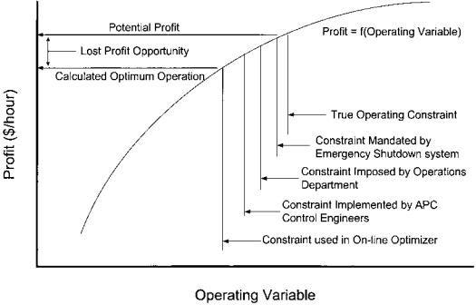
Control Systems for Commercial Reformers |
545 |
Figure 8 Constraint creep impact on optimization profitability.
added in the APC application by the control engineers to ensure that the operations imposed limit was not violated. Finally, the optimization engineers added a fourth constraint to protect the APC application. The result is a calculated optimal operation significantly moved from the potential optimal operation. Care must be taken to ensure that the normal variation in the unit operation does not cause the reformer unit to be shut down. A simple statistical analysis of the operation can establish the limits. Then, the constraints added by each layer of control must be checked not against the previous layer’s constraint but against the true operating constraint.
5.5.Implementation Plans for Real-Time Optimization
Implementation of a real-time optimization project on a catalytic reformer can be divided into four steps: (1) project analysis, (2) model development, (3) model on-line implementation, and (4) ongoing support and evaluation. Well-defined policies and procedures are established by companies routinely installing on-line optimization applications [30].
Project Analysis
In the project evaluation phase, the economic need for on-line optimization on a specific catalytic reformer is established, an economic envelope is defined, an
546 |
Turpin |
optimization objective function statement is developed, and the model requirements are specified. At this time, preliminary estimates of hardware, software, instrument, and analyzer additions and associated support requirements should be compiled. If the project is to be implemented by a third-party contractor, the final steps in this phase would be to prepare a request for quotation and select a vendor.
Model Development
The model development phase for a catalytic reformer process and economic optimization model has within it several milestones, the first of which is to establish a base operation for model configuration and calibration. A detailed function design of the model must be prepared that specifies not only the model specification but also hardware requirements, instrument and analyzer requirements, required APC modifications, planning department support requirements, an implementation plan, and a plan for ongoing maintenance. The model development phase includes the programming of the process configuration and the economic vectors used in the model objective function. Upon model completion, the model must be calibrated and tested. A model interface is then built for use by operations, engineering, and planning.
Model On-line Implementation
The catalytic reformer model on-line implementation should be done in two steps. First, the model is installed on-line in an open-loop mode. This initial openloop mode is used for testing of the following:
User interfaces (operations, engineering, and planning)
Plant process data to model connections
Model gains to the underlying APC controller gains
Model for robustness in solution
Model to controller connections
While in the open-loop mode, any document changes are completed prior to operator and support engineer training. Methodology for coordinating the input of economic values to the model must be prepared. Methodology for engineering reviews of the model performance and troubleshooting must also be prepared.
The second step in the catalytic reformer on-line implementation is to connect the model controller output targets to the APC controllers. The controller movements should be initially tightly constrained and the constraints relaxed as systems and communication links are retested.
Control Systems for Commercial Reformers |
547 |
Ongoing Support and Evaluation
Ongoing support of a catalytic reformer on-line optimization project starts with the integration of the optimization problem into the plant’s work practices. An on-line optimizer requires input and evaluation from all sources along the length of the control spectrum, from the technician in the instrument shop to the chief of the planning department.
On-line catalytic reformer optimization models require frequent review by operations management and support engineering. Initially, there will be many questions as to why the optimizer pushes the reformer into a particular operating zone. There are counteracting economic drivers that the reformer model may evaluate differently, which are based on rigorous calculation rather than a human using hunches and rules of thumb. As process objectives change, the ability of the reformer model to correctly represent the new conditions should be reviewed. This is particularly true when operating changes, mechanical repairs/changes, or economic changes have been made that push the reformer operation against a different set of constraints.
Operating plants are in a constant state of flux. They are responding to pressures from government agencies, environmental groups, corporate policy initiatives, improvements in process technology, and economic pressures from supply and demand. Periodic review need to be made of the economic boundaries and objective function in an on-line catalytic reformer optimizer. When appropriate, minor and major overhauls to the reformer optimization model must be incorporated.
6SUMMARY
Integration of the control systems into an effective management tool results in a safe and efficient operation of the catalytic reforming process [31]. This requires coordination of multiple disciplines within the planning, operations, engineering, management, and maintenance departments. Instrumentation and controls must be properly sized and designed to meet the processing objectives established by the planning function. The instrumentation must be properly installed and maintained in good working order to be effectively utilized. The operations group must implement the planned operation with the tools provided, make timely and accurate analyses of instrument and control problems and requirements, and effectively communicate those issues to the appropriate plant organization. Above all, each individual involved in the catalytic reforming unit control system must function in a manner that is consistent with safe design, maintenance, and operation of the facility.
548 |
Turpin |
REFERENCES
1.Murrill, P.W. Fundamentals of Process Control Theory; Instrument Society of America: Research Triangle Park, NC, 1981.
2.ASTM Manual on Hydrocarbon Analysis, 4th ed.; ASTM: Philadelphia, 1989.
3.Little, D.M. Catalytic Reforming; Penn Well: Tulsa, OK, 1985.
4.DMCplusw Multivariable Control Software Training Manual; Aspen Technology: Houston, TX 1998.
5.Rossi, R.J.; Lee, R.W.; Turpin, L.E. In Maximizing Reformer Profitability Against Mechanical Constraints Using a Kinetic Reaction Model; NPRA Computer Conference, November 1991.
6.Turpin, L.E. Catalytic reforming: real-time planning and optimization. Hydrocarbon Technol. Quart. 1997, 23–30.
7.Turpin, L.E.; Korchinski, W.J. Applying advanced controls to fired heaters. Petroleum Technol. Quart. 1999.
8.Summers, A.E. Setting the standard for safety-instrumented systems. Chem. Eng. 2000, 207 (13), 92–94.
9.Onderdonk, J.K. Understanding shutdown systems. Chem. Eng. 1986, 205 (7), 45– 50.
10.Martin, G.R. Heat-flux imbalances in fired heaters cause operating problems. Hydrocarbon Processing 1998, 77 (5), 103–109.
11.Dieck, R.H. Measurement Uncertainty Methods and Applications; Instrument Society of America: Research Triangle Park, NC, 1992.
12.McDonald, G.W.G. To judge reformer performance. Hydrocarbon Processing 1977, 55 (6), 147–150.
13.Advanced control and information systems. Hydrocarbon Processing. Maximizing reformer profitability against mechanical constraints using a kinetic model. (L. Kane, ed.) September, 1995, 277 (9).
14.Maxwell, J.B. Data Book on Hydrocarbons; Krieger: New York, 1977.
15.Turpin, L.E. Predicting Component Yields in a Commercial Catalytic Reformer Using a Kinetic Model, 222nd American Chemical Society National Meeting, 2001 Spring National Meeting.
16.Kern, D.Q. Process Heat Transfer; McGraw-Hill: New York, 1990.
17.Clevett, K.J. Process Analyzer Technology; Wiley-Interscience: New York, 1986.
18.McIntosh, B. Optimizing processes with on-line infrared monitoring. Control Eng.
1998.
19.Hugo, A. Limitations of model predictive controllers. Hydrocarbon Processing 2000, 79 (1), 83–88.
20.Gilsdorf, N.L.; Furfaro, A.P.; Rachford, R.H.; Schmidt, R.J.; York, D.L. Reforming processes for aromatics production. In Encyclopedia of Chemical Processing and Design; KcKetta, J.J., Ed.; Marcel Dekker: New York, 1994; Vol. 47, 92–113.
21.Martin, G.D.; Cline, R.P.; Turpin, L.E. Estimating control function benefits. Hydrocarbon Processing 1991, 70 (6), 68–73.
22.Ayral, T.E.; Stahl, D.E.; Glidewell, M.C. Expert systems aid plant operations managers. Hydrocarbon Processing 1998, 77 (11), 115–119.
Control Systems for Commercial Reformers |
549 |
23.Advanced control and information systems ’99, catalytic reformer advisor. Hydrocarbon Processing 1999, 78 (11), September (T. Ayral, ed.) p. 95.
24.White, D.C. Online optimization: what, where and estimating ROI. Hydrocarbon Processing 1997, 76 (6), 43–51.
25.Turpin, L.E.; Kim, H.C.; Yoon, H.S.; Lakshmanan, A.; Park, N.S. A reformer model for a petrochemical complex. Petroleum Technology Quarterly 2001, 133–139.
26.Yu, C.D.; Bluck, D.; Powel, R.; Turpin, L.E. Integration of Refinery Reactors into Flowsheet Simulation, AIChE 1997 Spring National Meeting, March 1997.
27.Verne, T.; Jerrit, B.; Bester, P. Unique approach to real-time optimization. Hydrocarbon Processing 1999, 78 (3), 53–60.
28.Friedman, Y.Z. Closed-loop optimization update—a step closer to fulfilling the dream. Hydrocarbon Processing 2000, 79 (1), 15–16.
29.Turpin, L.E. Reforming processes, benzene reduction. In Encyclopedia of Chemical Processing and Design; KcKetta, J.J., Ed.; Marcel Dekker: New York, 1994, Vol. 47, 113–133.
30.RT-OPT w Real-Time Optimization System User’s Manual, Release 3. Aspen Technology, 1998.
31.Turpin, L.E. Performance optimization through software integration. Today’s Refinery 2000, 15 (1), 9–11.