5R55W
.pdfTechnical Service Information
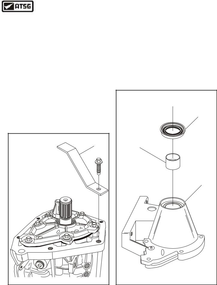
OVERDRIVE SUN GEAR AND ADAPTER PLATE
A 4
X 4
B
X |
|
|
W |
||
|
4 |
|
|
|
P |
|
|
- |
|
|
7 |
|
|
6 |
|
|
6 |
|
|
0 |
A |
A |
- |
|
||
|
X |
X |
X |
|
|
|
|
|
B |
|
|
A |
|
|
- |
|
|
0 |
|
|
|
6 |
6 |
|
|
|
X
X
7 |
- |
|
P |
|
2 |
L
2
B
X
4
X
X
X
4 |
A |
|
|
X |
X |
|
0.75 Ratio |
0.71 Ratio |
24 Teeth |
38 Teeth |
|
Copyright © 2004 ATSG |
Figure 160
OVERDRIVE SUN GEAR ADAPTER PLATE AND COAST CLUTCH HOUSING
P |
76 |
|
|
||
|
6 |
|
|
||
4 |
- |
|
0 |
- |
|
|
|
|
|||
W |
|
|
|
|
A |
|
|
|
|
A |
|
X |
|
|
|
|
|
|
|
|
|
|
|
0.75 Ratio
A |
4 |
X |
4 |
B |
|
||||
|
|
|||
|
|
|
4 |
A |
|
X |
X |
|
|
|
|
|
X |
|
|
|
X |
|
|
|
||
4 |
|
|
|
|
|
X |
|
||
B |
|
|
|
|
|
|
|||
|
|
|
|
|
|
|
X |
||
|
|
|
|
|
|
|
|
||
|
0.71 Ratio |
|
|
|
|
|
2 |
||
|
|
|
|
|
|
|
|
|
|
|
|
|
|
|
|
|
|
|
L |
X |
|
|
|
|
|
|
|
P |
2 |
|
|
|
|
|
|
|
|
||
X |
|
|
|
|
|
7 |
- |
|
|
|
|
|
|
|
|
|
|
||
X |
|
|
|
|
6 |
|
|
|
|
|
|
|
|
|
|
|
|
||
X |
|
|
|
6 |
|
|
|
|
|
X |
|
0 |
|
|
|
|
|
||
|
|
A |
|
|
|
|
|
|
|
|
|
B |
- |
|
|
|
|
|
|
|
|
|
|
|
|
|
|
|
|
Different Configuration Where
Adapter Plate Splines Into The
Coast Clutch Housing
Copyright © 2004 ATSG
Figure 161
AUTOMATIC TRANSMISSION SERVICE GROUP |
91 |
|
Technical Service Information
COAST CLUTCH |
DRUM ASSEMBLY |
9 |
9 |
/ |
1 |
0 |
/ |
9 |
0 |
B |
A |
- |
9 |
6 |
6 |
L |
7 |
P- |
4 |
W |
X |
Copyright © 2004 ATSG |
|
OVERDRIVE |
|
BAND |
BAND STRUT |
BAND STRUT |
SERVO SIDE |
ADJUST SIDE |
|
9 |
|
9 |
|
/ |
|
1 |
|
0 |
|
/ |
|
9 |
|
0 |
|
B |
|
A |
|
- |
|
9 |
|
6 |
|
6 |
|
L |
|
7 |
|
P- |
|
4 |
|
W |
|
X |
|
Copyright © 2004 ATSG |
Figure 162 |
Figure 163 |
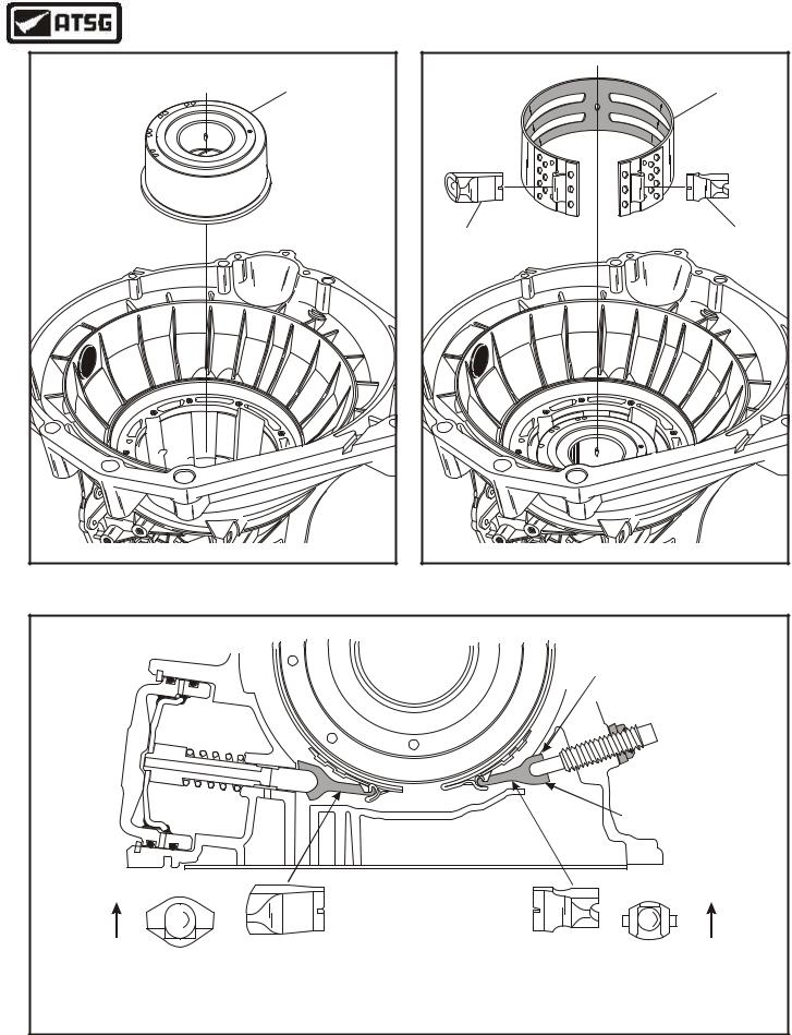
CORRECT OVERDRIVE BAND STRUT INSTALLATION
Small Notch
 Facing Up
Large Notch
Facing Down
End View |
End View |
Faces Up |
Faces Up |
Caution: The apply or servo side must have the strut installed that is illustrated above, and installed in the direction shown above.
Caution: The adjustment side must have the strut installed that is illustrated above, and installed in the direction shown above.
Figure 164
92 |
AUTOMATIC TRANSMISSION SERVICE GROUP |
|

Technical Service Information
INTERNAL COMPONENTS (Cont'd)
46.Install the pre-assembled coast clutch housing, as shown in Figure 162, by rotating back and forth to engage clutches on hub, until fully seated.
47.Install the overdrive band into transmission and around the coast clutch housing, as shown in Figure 163.
48.Install the overdrive band struts on each side
of the band, exactly as shown in Figure 163.
Caution: The anchor or adjustment side must have strut installed that is illustrated in Figure 164 and must be installed with the small notch facing the top of transmission.
The apply or servo side must also be installed, as shown in Figure 164.
50.Install pump gasket onto the pre-assembled oil pump, as shown in Figure 166.
51.Place the "H" gauge with the previously set center rod onto the oil pump in the opposite direction, with the center rod placed over the selective washer, as shown in Figure 166.
52.Measure with a feeler gage between the center rod and selective thrust washer, as shown in Figure 166.
53.Front end clearance should be .012" - .018". Change the selective oil pump thrust washer from the chart below, as necessary, to achieve proper front end clearance.
Continued on Page 94
49.Install "H" gauge onto case pump surface and move center rod down to surface on the coast clutch where selective thrust washer rides, as shown in Figure 165.
9 |
9 |
/ |
1 |
0 |
/ |
9 |
0 |
B |
A |
- |
9 |
6 |
6 |
L |
7 |
- |
P |
4 |
W |
X |
Copyright © 2004 ATSG |
Figure 165
SELECTIVE OIL PUMP THRUST WASHER CHART |
||||||||||||||||
THICKNESS |
|
|
|
|
|
PART NO. |
|
|
|
I.D. COLOR/NO. |
||||||
.066" - .069" |
|
XW4Z-7D014-XA Brown/"8" |
||||||||||||||
.073" - .075" |
|
XW4Z-7D014-NA |
|
|
Red/"4" |
|||||||||||
.080" - .082" |
|
XW4Z-7D014-RA Black/"6" |
||||||||||||||
.087" - .089" |
|
XW4Z-7D014-YA Orange/"9" |
||||||||||||||
.094" - .096" |
|
XW4Z-7D014-ZA |
|
|
Purple/"10" |
|||||||||||
|
|
|
|
|
|
|
|
|
4 |
WX |
|
|
|
|
|
|
|
|
|
|
|
|
|
|
- |
P |
|
|
|
|
|
|
|
|
|
|
|
|
|
|
|
7 |
|
|
D |
|
|
|
|
|
|
|
|
|
|
|
|
D |
|
|
0 4 Y |
|
|
|
|
||
|
|
|
|
|
|
0 |
|
|
|
|
A M |
A 1 |
|
|
|
|
|
|
|
|
|
4 |
|
|
|
|
|
|
|
|
|
|
|
|
|
|
|
3 |
d |
|
|
|
|
|
|
|
|
|
||
|
|
|
|
r |
|
|
|
|
|
|
|
|
|
|||
|
|
|
|
o |
|
|
|
|
|
|
|
|
|
|
||
|
|
|
|
G |
F |
|
|
|
|
|
|
|
|
|
|
|
|
|
F |
5 |
|
|
|
|
|
|
|
|
|
|
|
|
|
|
P |
|
|
|
|
|
|
|
|
|
|
|
|
|
||
C |
|
|
|
|
|
|
|
|
|
|
|
|
|
|
||
|
|
|
|
|
|
|
|
|
|
|
|
|
|
|
||
|
|
|
|
|
|
|
|
|
|
|
|
|
|
|
|
|
|
|
|
|
|
|
|
|
|
|
|
|
|
|
|
|
d |
|
|
|
|
|
|
|
|
|
|
|
|
|
|
|
r |
|
|
|
|
|
|
|
|
|
|
|
|
|
|
|
o |
|
|
|
|
|
|
|
|
|
|
|
|
|
|
|
|
F |
|
|
A |
|
- |
|
|
|
|
|
|
|
|
|
|
|
|
|
|
|
5A |
|
|
|
|
|
|
|
|
|
|
|
|
|
||
|
|
|
23 |
|
|
|
|
|
|
|
|
|
|
|
|
|
|
|
|
|
B |
|
|
|
|
|
|
|
|
|
|
|
|
|
|
|
|
7- |
|
|
|
|
|
|
|
|
|
|
|
|
|
|
|
|
|
P |
|
|
|
|
|
|
|
|
|
|
|
|
|
|
|
|
4 |
WX |
|
|
|
|
|
|
|
|
|
|
|
|
|
|
|
|
F |
|
|
|
|
|
|
|
|
|
|
|
|
|
|
|
|
|
R |
|
|
|
|
|
|
|
|
|
|
|
|
|
|
|
|
|
|
|
|
|
Copyright © 2004 ATSG |
||||
Figure 166
AUTOMATIC TRANSMISSION SERVICE GROUP |
93 |
|

Technical Service Information
OIL PUMP ASSEMBLY |
RETAINING BOLTS |
(8 REQUIRED) |
OIL PUMP |
ASSEMBLY |
89 |
OIL PUMP |
TO CASE |
GASKET |
9 |
9 |
/ |
1 |
0 |
/ |
9 |
0 |
B |
A |
- |
9 |
6 |
6 |
L |
7 |
P- |
4 |
W |
X |
Copyright © 2004 ATSG |
INTERNAL COMPONENTS (Cont'd)
54.Install the oil pump to case gasket into case, as shown in Figure 167, and align holes.
55.Lubricate the case bore where the "O" ring rides with a small amount of Trans-Jel®.
56.Install the pre-assembled oil pump assembly into the case, as shown in Figure 167, using care not to damage the pump "O" ring.
57.Install the eight oil pump assembly retaining bolts, and torque to 25Nm (18 ft.lb.), as shown in Figure 168.
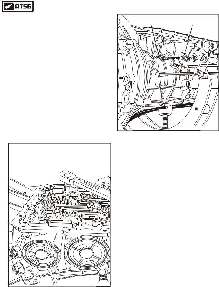
58.Rotate the transmission so that the valve body surface is facing up, as shown in Figure 169.
59.Torque the center support retaining bolt down to 11 Nm (100 in.lb.), (See Figure 169).
Continued on Page 95
TORQUE PUMP BOLTS |
TO 25 Nm (18 ft.lb.) |
Copyright © 2004 ATSG |
Figure 167 |
Figure 168 |
94 |
AUTOMATIC TRANSMISSION SERVICE GROUP |
|
Technical Service Information
INTERNAL COMPONENTS (Cont'd)
63.Install new locking nuts on both band adjusting screws, using care not to let the adjusting screw come out, so that the band anchors will not fall out and into transmission (See Figure 170).
64.Adjust the overdrive band by turning adjusting screw in while holding the lock nut. Torque the adjusting screw to 14 Nm (10 ft.lb.) and then back out exactly 2 full turns for W/S models in trucks and 1-1/2 turns for S models in cars. Refer to Figure 170.
65.Adjust intermediate band by turning adjusting screw in while holding the lock nut. Torque the adjusting screw to 14 Nm (10 ft.lb.) and then back out exactly 2 full turns for W/S models in trucks and 1-1/2 turns for S models in cars. Refer to Figure 170.
66.Torque both locking nuts to 54 N•m (40 ft.lb.), while holding adjusting screw.
Continued on Page 97
OVERDRIVE BAND |
INTERMEDIATE BAND |
ADJUSTING SCREW |
ADJUSTING SCREW |
|
F |
|
dor |
|
Copyright © 2001 ATSG |
Figure 170
TORQUE CENTER SUPPORT BOLT |
|
||||
TO 11 Nm (100 in.lb.) |
|
|
|||
8 |
|
|
|
|
|
A |
|
|
|
|
|
G |
F |
|
|
|
C |
|
or |
|
|
A |
|
|
|
d |
6 |
|
0 |
|
|
R |
|
||
|
|
3 |
5 |
|
|
|
|
T9 |
3 |
|
|
|
|
8 |
|
|
|
|
0 |
A |
|
|
|
|
4 |
A |
|
|
|
5 |
|
|
|
||
6 |
9 |
|
F |
|
|
|
1 |
|
|
|
|
3 |
|
o |
|
||
R |
|
dr |
|
|
|
|
|
Copyright © 2004 ATSG |
|||
Figure 169
AUTOMATIC TRANSMISSION SERVICE GROUP |
95 |
|
Technical Service Information
|
|
|
|
|
|
|
|
DETENT SPRING BOLT |
|
VALVE BODY |
|
|
|
|
|
|
|
|
"1" REQUIRED |
DETENT |
RETAINING BOLTS |
|
|
|
|
|
VALVE BODY |
|
(30mm LENGTH) |
SPRING |
"18" REQUIRED |
|
VALVE BODY |
|
|
|
|
RETAINING BOLT |
|
|
|
(40mm LENGTH) |
|
|
|
|
|
"1" REQUIRED |
|
|
|
|
||
RETAINING BOLTS |
|
|
|
|
(45mm LENGTH) |
|
|
|
|
|
"18" REQUIRED |
|
|
|
|
|
|
|
|
|
|
(40mm LENGTH) |
|
|
|
|
|
|
|
|
|
|
|
|
|
|
|
VALVE BODY |
|
|
|
|
|
|
|
|
|
|
RETAINING BOLT |
|
|
|
||
|
|
|
|
|
"1" REQUIRED |
|
|
|
|
|
|
|
|
|
|
(27mm LENGTH) |
|
|
|
||
VALVE BODY AND |
|
|
|
|
|
|
|
|
|
|
SPACER PLATE |
|
|
|
|
|
|
|
|
|
|
ASSEMBLY |
|
|
|
|
|
|
|
|
|
|
|
|
|
|
VALVE BODY |
|
|
|
|
|
|
|
|
|
|
ALIGNMENT |
|
|
|
|
|
|
|
|
|
|
|
DOWELS |
|
|
|
|
|
|
|
|
|
|
|
|
|
|
|
6 |
|
|
|
|
|
|
|
|
|
|
2 |
|
|
|
|
|
|
|
|
|
|
- |
|
|
|
|
|
|
|
|
|
|
1 |
8 |
|
|
|
|
|
|
|
|
|
|
A |
|
|
|
|
|
|
|
|
|
|
G |
F |
|
|
|
|
|
CA |
|
|
|
|
|
o |
|
|
|
|
|
|
||
|
|
|
rd |
|
R3 |
653 |
|
0 |
|
|
|
|
|
|
|
|
|
|
|||
|
|
|
|
|
|
|
|
|
||
|
|
|
|
|
T9 |
8 |
|
|
|
|
|
|
|
|
|
|
|
|
|
|
|
|
|
0 |
|
|
A |
|
|
|
|
|
|
4 |
A |
|
|
|
|
|
|
||
|
5 |
|
|
|
|
|
|
|
||
|
6 |
9 |
|
|
|
F |
|
|
||
|
|
1 |
|
|
|
|
|
|
||
|
3 |
|
|
|
o |
|
|
|
||
|
R |
|
|
|
|
dr |
|
|
|
|
|
|
|
|
|
|
|
|
|
|
Copyright © 2004 ATSG |
Figure 171
96 |
AUTOMATIC TRANSMISSION SERVICE GROUP |
|
Technical Service Information
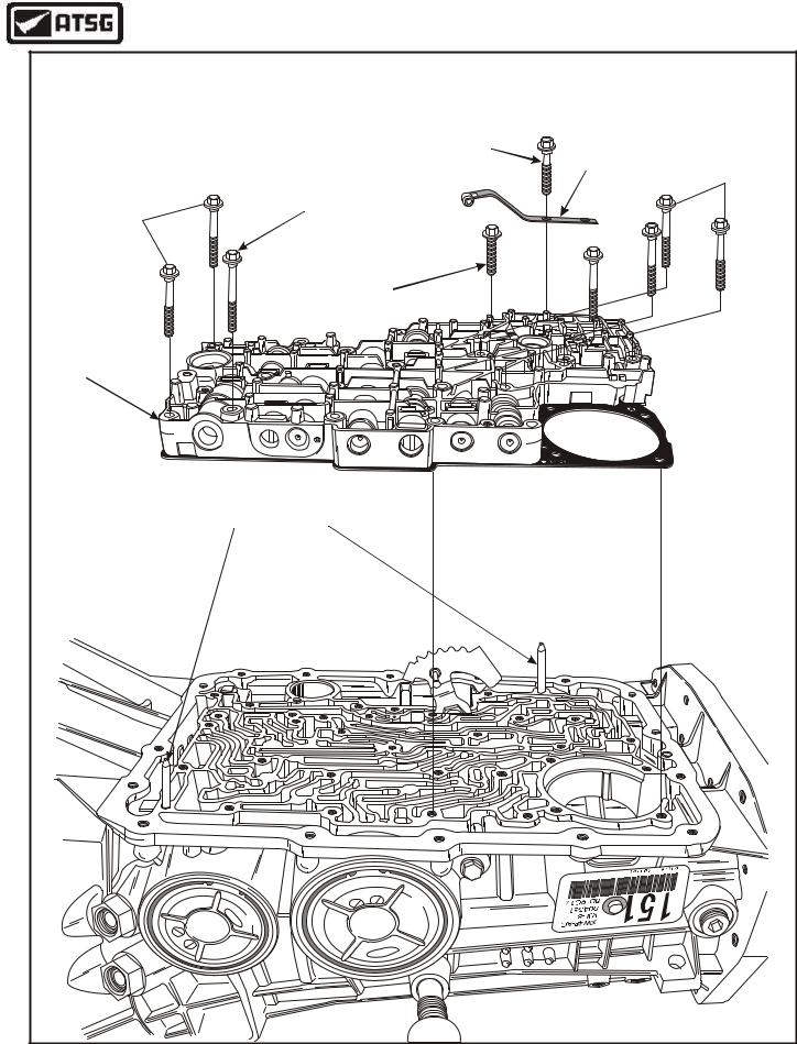
INTERNAL COMPONENTS (Cont'd)
67.Install the two valve body alignment dowels in the locations shown in Figure 171.
68.Install the pre-assembled valve body and spacer plate, as shown in Figure 171.
Caution: Ensure that manual valve is engaged on the inside detent lever properly.
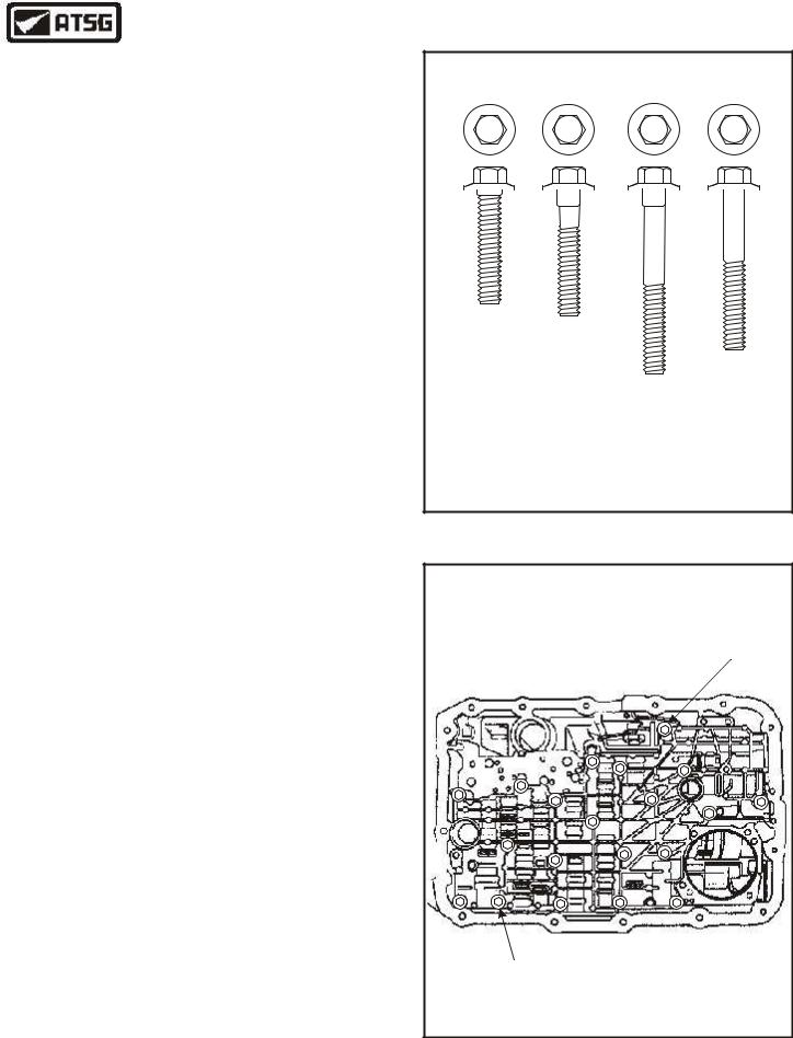
69.There are four different lengths of valve body bolts, as shown in Figure 172.
70.Install the 27mm length bolt finger tight only, in the location shown in Figure 173.
71.Install the 45mm length bolt finger tight only, in the location shown in Figure 173.
72.Install the remaining 18, 40mm length valve body bolts, in locations shown in Figure 173, and finger tighten only at this time.
73.Install the detent spring assembly, as shown in Figure 171, using the only 30mm length bolt, and finger tighten only at this time.
Continued on Page 99
VALVE BODY BOLT IDENTIFICATION
8 mm |
8 mm |
|
8 mm |
8 mm |
||||||||||||
|
|
|
|
|
|
|
|
|
|
|
|
|
|
|
|
|
|
|
|
|
|
|
|
|
|
|
|
|
|
|
|
|
|
|
|
|
|
|
|
|
|
|
|
|
|
|
|
|
|
|
|
|
|
|
|
|
|
|
|
|
|
|
|
|
|
|
|
|
|
|
|
|
|
|
|
|
|
|
|
|
|
|
|
|
|
|
|
|
|
|
|
|
|
|
|
|
|
|
|
|
|
|
|
|
|
|
|
|
|
|
|
|
|
|
|
|
|
|
Valve |
Detent |
|
Body |
||
Spring |
||
(1) |
(1) |
|
(27mm) |
(30mm) |
|
|
Valve |
|
|
Body |
|
|
Valve |
|
|
(1) |
|
Shown |
Body |
|
(45mm) |
||
Actual Size |
(18) |
|
(40mm) |
||
|
||
|
Copyright © 2004 ATSG |
Figure 172
VALVE BODY
RETAINING BOLT "1" REQUIRED (27mm LENGTH)
VALVE BODY
RETAINING BOLT
"1" REQUIRED
(45mm LENGTH)
THE REMAINING 18 VALVE BODY BOLTS ARE 40mm LENGTH
Figure 173
AUTOMATIC TRANSMISSION SERVICE GROUP |
97 |
|
Technical Service Information
|
|
|
|
|
|
|
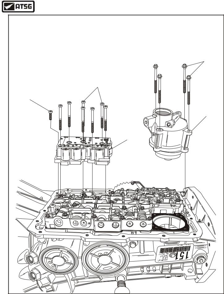
LOW/REVERSE SERVO |
|
|
|
|
|
|
|
RETAINING BOLTS |
|
|
|
|
|
|
|
(70mm LENGTH) |
|
|
|
|
SOLENOID BODY |
|
||
|
|
|
|
RETAINING BOLTS |
|
||
|
|
|
|
(63mm LENGTH) |
|
||
SOLENOID BODY |
|
|
|
|
|
|
|
RETAINING BOLT |
|
|
|
|
|
|
|
(25mm LENGTH) |
|
|
|
|
|
|
|
|
|
|
|
|
|
|
LOW/REVERSE |
|
|
|
|
|
|
|
SERVO ASSEMBLY |
|
|
|
|
|
|
|
SOLENOID BODY |
|
|
|
|
|
|
|
ASSEMBLY |
|
|
|
|
|
|
|
6 |
|
|
|
|
|
|
|
2 |
|
|
|
|
|
|
|
- |
|
|
|
|
|
|
|
1 |
8 |
|
|
|
|
|
|
|
A |
|
|
|
|
|
|
|
G |
F |
|
|
|
|
CA |
|
|
|
o |
|
|
|
||
|
|
|
rd |
R |
653 |
|
0 |
|
|
|
|
3 |
|
|
|
|
|
|
|
T9 |
8 |
|
|
|
|
|
|
|
|
|
|
|
|
0 |
|
A |
|
|
|
|
4 |
A |
|
|
|
|
|
|
5 |
|
|
|
|
|
|
|
6 |
9 |
|
|
F |
|
|
|
|
1 |
|
|
|
|
|
|
3 |
|
|
o |
|
||
|
R |
|
|
|
dr |
|
|
|
|
|
|
|
|
|
Copyright © 2004 ATSG |
Figure 174
98 |
AUTOMATIC TRANSMISSION SERVICE GROUP |
|