

5R55W
.pdfTechnical Service Information
REAR PLANETARY |
RING GEAR THRUST |
BEARING (NO. 10) |
REVERSE DRUM |
AND LOW SPRAG |
ASSEMBLY |
LOW/REVERSE |
BAND ASSEMBLY |
Copyright © 2004 ATSG |
Figure 140
INTERNAL COMPONENTS (Cont'd)
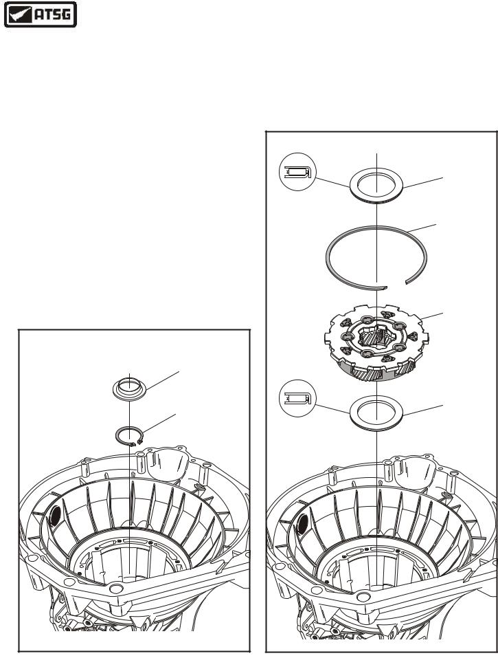
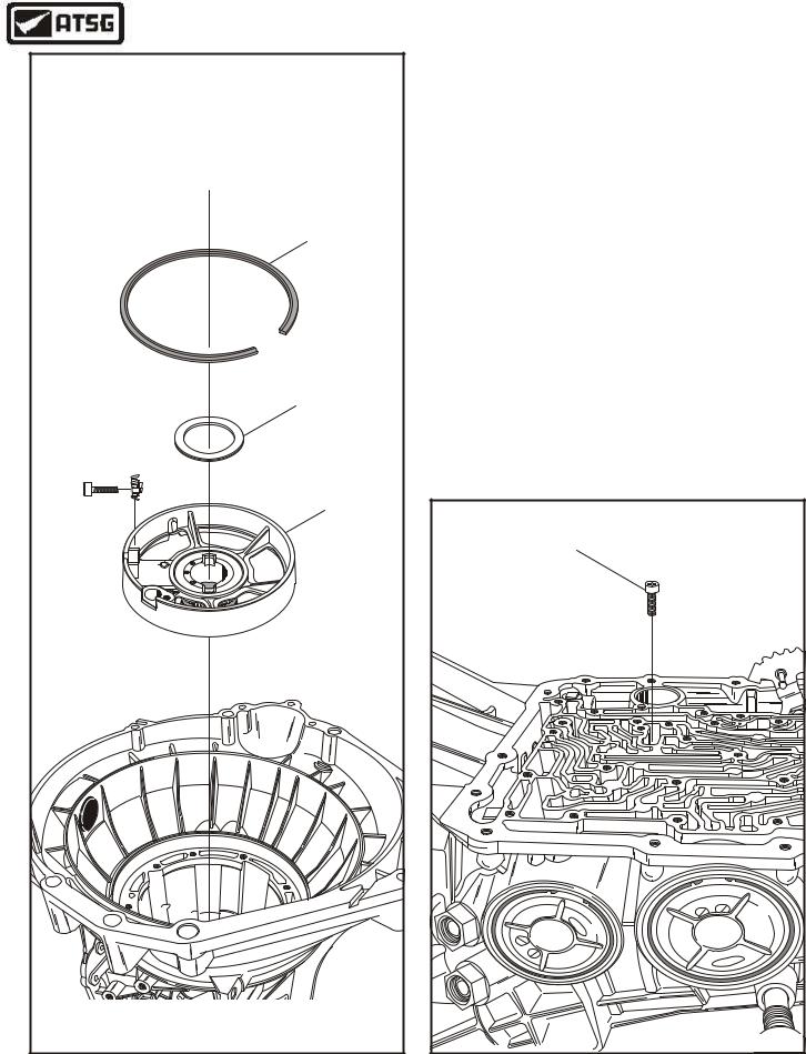
8.Rotate transmission in fixture so that front of case is facing up, as shown in Figure 140.
9.Install the reverse band into transmission, as shown in Figure 140, ensuring that it engages on the band anchor lugs in the case.
10.Compress the reverse band enough to engage the reverse band laver into the notches in the reverse band.
11.Install reverse drum and low sprag assembly into the reverse band, as shown in Figure 140, by rotating in a clock-wise direction untill it falls into position.
12.Install rear planetary ring gear thrust bearing (No. 10) into the case in the direction that is shown in Figure 140.
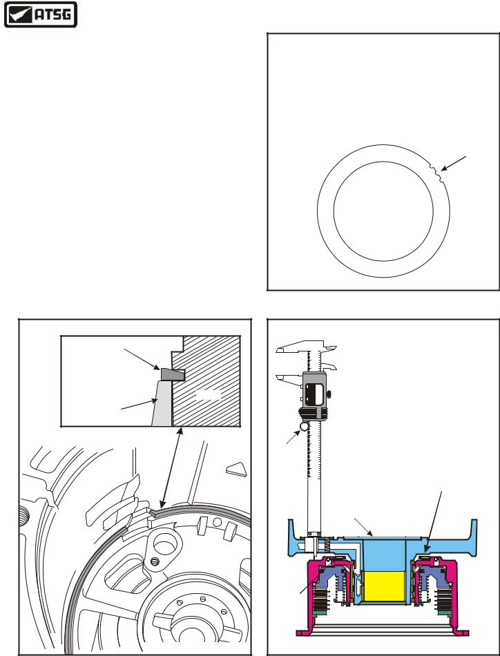
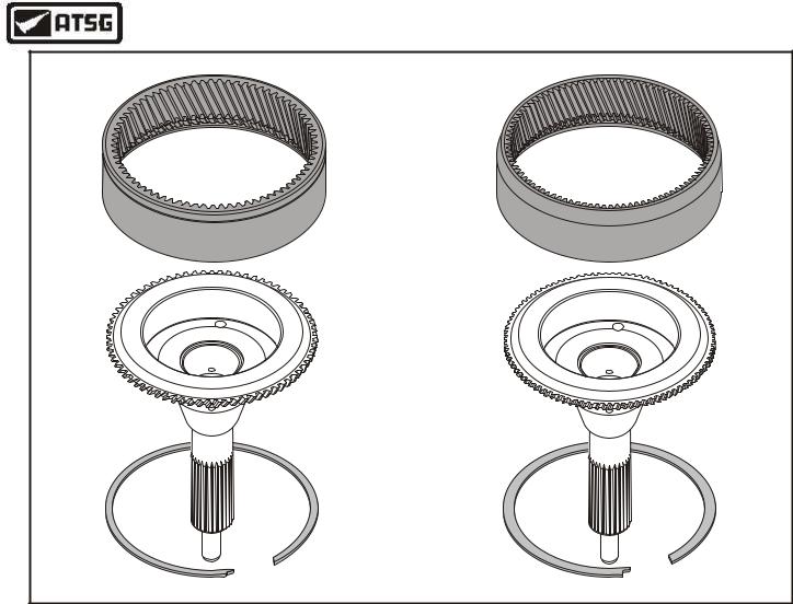
13.Install the pre-assembled rear planetary ring gear that has the seal ring with the notches in it, as shown in Figure 141, and ensure that it is fully seated against bearing.
Continued on Page 82
REAR PLANETARY |
RING GEAR |
Copyright © 2004 ATSG |
Figure 141
AUTOMATIC TRANSMISSION SERVICE GROUP |
81 |
|
Technical Service Information
INTERNAL COMPONENTS (Cont'd)
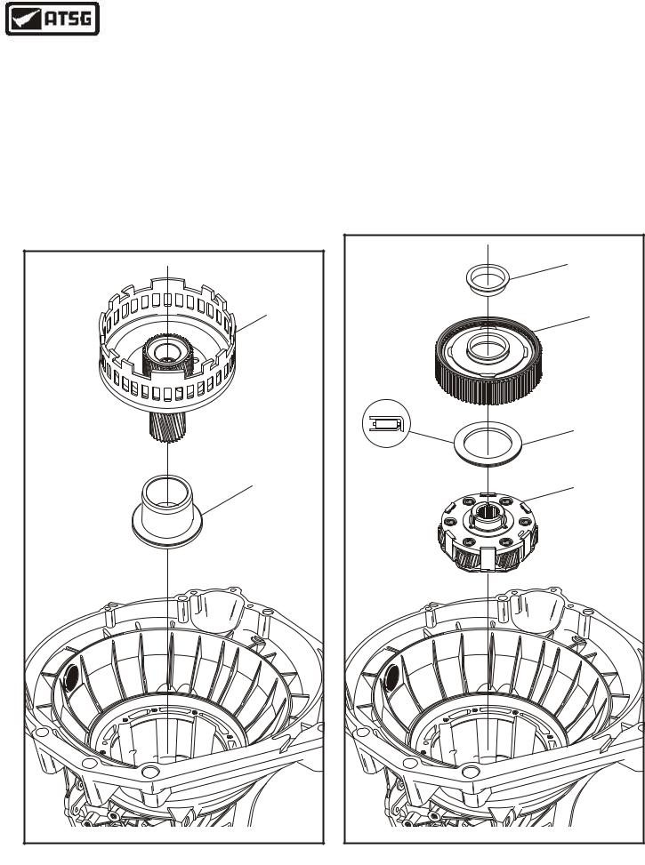
14.Install a new output shaft snap ring onto output shaft, as shown in Figure 142, and ensure that it is fully seated.
Note: Ford Motor Company recommends a new snap ring in this location "every time", and after this ring is installed you may now remove the temporary strap.
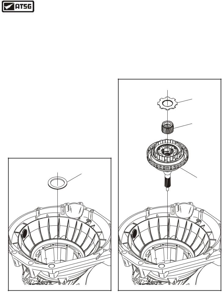
15.Install the plastic rear lube dam into the ring gear in the direction shown in Figure 142.
16.Install the rear planetary thrust bearing (No. 9) on top of rear ring, in the direction shown in Figure 143, and retain with small amount of Trans-Jel®.
17.Install the rear planetary carrier assembly, as shown in Figure 143, by rotating into position until fully seated.
18.Install the rear planetary carrier snap ring into groove in the reverse drum and ensure that it is fully seated (See Figure 143).
Note: Reverse drum must be lifted up to install the snap ring.
REAR LUBE DAM |
OUTPUT SHAFT |
SNAP RING |
Copyright © 2004 ATSG |
Figure 142
19.Install the rear planetary thrust bearing (No. 8) on top of the rear planetary carrier, in direction shown in Figure 143, and retain with a small amount of Trans-Jel®.
Continued on Page 83
REAR PLANETARY |
THRUST BEARING |
(NO. 8) |
REAR PLANETARY |
SNAP RING |
REAR PLANETARY |
ASSEMBLY |
REAR PLANETARY |
THRUST BEARING |
(NO. 9) |
Copyright © 2004 ATSG |
Figure 143
82 |
AUTOMATIC TRANSMISSION SERVICE GROUP |
|
Technical Service Information
INTERNAL COMPONENTS (Cont'd)
20.Install the "Tall" low/reverse spacer on top of the No. 8 thrust bearing, in the direction shown in Figure 144.
21.Install the input sun gear and shell assembly, as shown in Figure 144.
22.Install the forward planetary carrier with the No. 6 thrust washer, as shown in Figure 145, by rotating into position.
Caution: Ensure that snapped in thrust washer is still in position.
INPUT SUN SHELL |
AND SUN GEAR |
"TALL" |
LOW/REVERSE |
SPACER |
Copyright © 2004 ATSG |
Figure 144
23.Install forward planetary carrier thrust bearing (No. 7) in the direction shown in Figure 145, and retain with small amount of Trans-Jel®.
24.Install the forward ring gear and hub, as shown in Figure 145, by rotating into position.
25.Install forward clutch thrust washer (No. 6B), as shown in Figure 145.
Continued on Page 84
|
|
FORWARD CLUTCH |
|
|
THRUST WASHER |
|
|
(NO. 6B) |
|
|
FORWARD RING |
|
|
GEAR AND HUB |
|
|
FORWARD PLANET |
|
|
THRUST BEARING |
|
|
(NO. 7) |
|
|
FORWARD PLANET |
D1 E4A |
|
ASSEMBLY |
A |
|
|
C |
|
o F |
-5 |
|
|
5 |
d r |
|
0 |
|
|
D |
|
|
P4 WXFR |
|
|
|
Copyright © 2004 ATSG |
|
Figure 145
AUTOMATIC TRANSMISSION SERVICE GROUP |
83 |
|
Technical Service Information
INTERNAL COMPONENTS (Cont'd)
26.Install forward clutch thrust bearing (No 6A) onto the back side of pre-assembled forward clutch drum, in direction shown in Figure 146, and retain with a small amount of Trans-Jel®.
27.Install forward clutch thrust bearing (No 5) on front side of forward clutch drum, in direction shown in Figure 146, and retain with a small amount of Trans-Jel®.
28.Install forward clutch housing, with bearings, as an assembly, as shown in Figure 146.
29.Caution: The thrust bearing (No 4) that goes between direct clutch drum and center support is "Selective" and a measurement must be made before installation.
FORWARD CLUTCH |
THRUST BEARING |
(NO. 5) |
FORWARD CLUTCH |
DRUM ASSEMBLY |
FORWARD CLUTCH |
THRUST BEARING |
(NO. 6A) |
Copyright © 2004 ATSG |
Figure 146
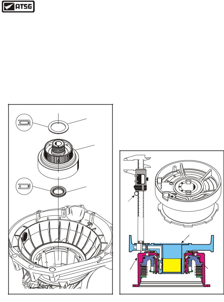
30.Assemble the selective bearing, direct clutch housing and center support, on the bench, as shown in Figure 147.
31.Measure with a dial caliper through the speed sensor hole down to the surface of the direct clutch housing, as shown in Figure 147, and record this as dimension "A".
32.After you have recorded the first measurment, install the pre-assembled direct clutch housing, as shown in Figure 148.
33.Install the number 4 thrust bearing in position on the direct clutch drum, in the direction that is shown in Figure 148.
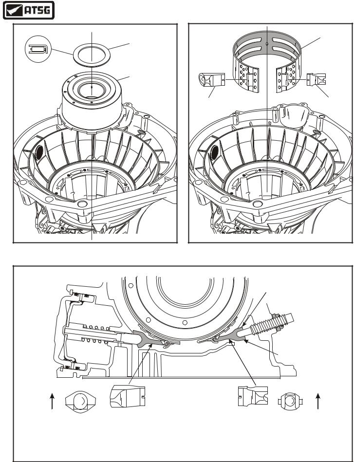
34.Install the intermediate band into transmission and around the direct clutch housing, as shown in Figure 149.
35.Install the intermediate band struts on each side of the band exactly as shown in Figure 150.
Continued on Page 86
|
|
0 |
1 |
|
|
|
|
|
|
|
|
|
2 |
|
|
10 |
|
4 3 |
|
|
|
|
5 |
|
|
|
|
6 |
|
|
20 |
|
8 7 |
|
|
|
|
9 |
|
|
30 |
|
1 |
|
|
|
2 1 |
|
|
|
|
|
3 |
|
|
40 |
|
4 |
|
|
|
6 5 |
|
|
0 mm/in |
60 50 |
OFF -POWER AUTO |
2009 8 7IN |
|
47253 1 . |
|
|||
|
|
|
5 |
96 |
|
|
|
6 |
|
|
70 |
|
8 7 |
M 07 |
|
|
1624 |
||
|
|
|
9 |
|
|
80 |
|
3 |
|
|
|
2 1 |
|
|
|
|
|
3 |
|
|
90 |
|
4 |
|
|
|
5 |
|
|
|
|
|
6 |
|
|
100 |
|
7 |
|
|
|
4 9 8 |
|
|
|
110 |
|
1 |
|
|
|
3 2 |
|
|
DIAL |
120 |
|
7 6 5 4 |
|
CALIPER |
130 |
|
2 1 5 9 8 |
|
|
140 |
|
5 4 3 |
|
|
|
|
6 |
|
|
150 |
|
9 8 7 |
|
mm |
|
|
6 |
|
|
|
in |
|
|
|
|
DIGITAL |
ELECTRONIC |
CENTER |
|
|
C |
|
|
|
|
ALIPER |
|
|
|
|
|
SUPPORT |
|
|
|
|
|
NO. 4 |
DIRECT |
|
|
|
SELECTIVE |
CLUTCH |
|
|
|
THRUST |
HOUSING |
|
|
|
BEARING |
|
|
|
|
Copyright © 2004 ATSG |
Figure 147
84 |
AUTOMATIC TRANSMISSION SERVICE GROUP |
|
Technical Service Information
DIRECT CLUTCH |
"SELECTIVE" |
THRUST BEARING |
(NO. 4) |
"Selective" |
DIRECT CLUTCH |
DRUM ASSEMBLY |
Copyright © 2004 ATSG |
Figure 148
|
INTERMEDIATE |
|
BAND |
BAND STRUT |
BAND STRUT |
SERVO SIDE |
ADJUST SIDE |
|
Copyright © 2004 ATSG |
Figure 149
CORRECT INTERMEDIATE BAND STRUT INSTALLATION
Small Notch
 Facing Up
Large Notch
Facing Down
End View |
End View |
Faces Up |
Faces Up |
Caution: The apply or servo side must have the strut installed that is illustrated above, and installed in the direction shown above.
Caution: The adjustment side must have the strut installed that is illustrated above, and installed in the direction shown above.
Figure 150
AUTOMATIC TRANSMISSION SERVICE GROUP |
85 |
|
Technical Service Information
CENTER SUPPORT |
"TAPERED" |
SNAP RING |
CENTER SHAFT |
THRUST BEARING |
(NO. 3) |
CENTER SUPPORT |
ASSEMBLY |
96 |
M 07 |
1624 |
Copyright © 2004 ATSG |
INTERNAL COMPONENTS (Cont'd)
36.Install the center support assembly, ensuring that you align the hole for the center support with the proper passage (See Figure 151).
37.Loosely install the center support retaining bolt as shown in Figure 152.
Continued on Page 87
CENTER SUPPORT |
|
|
|
|
|
|
RETAINING BOLT |
|
|
|
|
|
|
(20mm LENGTH) |
|
|
|
|
|
|
8 |
|
|
|
|
|
|
A |
|
|
|
|
|
|
G |
F |
|
|
|
C |
|
|
|
or |
|
|
A |
|
|
|
|
d |
6 |
|
0 |
|
|
|
R |
|
||
|
|
|
3 |
5 |
|
|
|
|
|
T |
38 |
|
|
|
|
|
9 |
|
|
|
|
|
0 |
A |
|
|
|
|
4 |
A |
|
|
|
|
|
5 |
|
|
|
|
|
|
6 |
9 |
|
|
F |
|
|
|
1 |
|
|
|
|
|
3 |
|
|
o |
||
|
R |
|
|
|
dr |
|
|
|
|
Copyright © 2004 ATSG |
|||
Figure 151 |
Figure 152 |
86 |
AUTOMATIC TRANSMISSION SERVICE GROUP |
|
Technical Service Information
INTERNAL COMPONENTS (Cont'd)
38.Install the center support snap ring with the opening in the snap ring to the opening in the center support, as shown in Figure 153.
39.Now we must once again measure with the dial caliper through the speed sensor hole down to the surface of the direct clutch housing with all of the parts installed in the case, as shown in Figure 155, and record this as dimension "B".
40.Subtract previously recorded dimension "A" from now recorded dimension "B", and this will give you the rear end clearance.
Example: Dimension "B" = .735"
Dimension "A" = .725"
Difference |
= .010" |
41.Rear end clearance should be .008" to .012". Change the selective No. 4 thrust bearing using the chart in Figure 154, as necessary to arrive at the proper end play.
Continued on Page 88
SELECTIVE NO. 4 THRUST BEARING CHART
THICKNESS |
PART NO. |
I.D. NOTCHES |
.104" - .110" |
XW4Z-7D014-CA |
None |
.111" - .117" |
XW4Z-7D014-DA |
One |
.118" - .125" |
XW4Z-7D014-EA |
Two |
.126" - .132" |
XW4Z-7D014-FA |
Three |
I.D. NOTCHES
Figure 154
"TAPERED" |
SNAP RING |
CASE |
CENTER SUPPORT |
ASSEMBLY |
Copyright © 2004 ATSG |
Figure 153
|
|
|
|
MEASURING DIMENSION "B" |
|
|
0 |
1 |
|
|
|
|
|
|
|
|
|
2 |
|
|
10 |
|
4 3 |
|
|
|
|
5 |
|
|
|
|
6 |
|
|
20 |
|
8 7 |
|
|
|
|
9 |
|
|
30 |
|
1 |
|
|
|
2 1 |
|
|
|
|
|
3 |
|
|
40 |
|
4 |
|
|
|
6 5 |
|
|
0 mm/in |
60 50 |
OFF -POWER AUTO |
2009 8 7IN |
|
47353 2 1 . |
|
|||
|
|
|
5 |
|
|
70 |
|
6 |
|
|
|
7 |
|
|
|
|
|
8 |
|
|
|
|
9 |
|
|
80 |
|
3 |
|
|
|
2 1 |
|
|
|
|
|
3 |
|
|
90 |
|
4 |
|
|
|
5 |
|
|
|
|
|
6 |
|
|
100 |
|
7 |
|
|
|
4 9 8 |
|
|
|
110 |
|
1 |
|
|
|
3 2 |
|
|
DIAL |
120 |
|
7 6 5 4 |
|
CALIPER |
130 |
|
2 1 5 9 8 |
|
|
150 140 |
|
6 9 8 7 6 5 4 3 |
Checking For End |
mm |
|
|
in |
Clearance Here |
|
|
|
ELECTRONIC |
|
|
|
DIGITAL |
CENTER |
|
|
|
C |
|
SUPPORT |
|
|
ALIPER |
|
|
|
|
|
|
|
NO. 4 |
|
|
|
|
SELECTIVE |
|
|
|
|
THRUST |
|
|
|
|
BEARING |
|
|
|
|
|
|
|
|
Copyright © 2004 ATSG |
Figure 155
AUTOMATIC TRANSMISSION SERVICE GROUP |
87 |
|
Technical Service Information
INTERNAL COMPONENTS (Cont'd)
42.Install the center shaft to center support thrust bearing (No. 3) onto the center support, as shown in Figure 156.
43.Install the pre-assembled overdrive carrier and center shaft assembly, as shown in Figure 157, ensuring that it is splined into the forward clutch housing and fully seated.
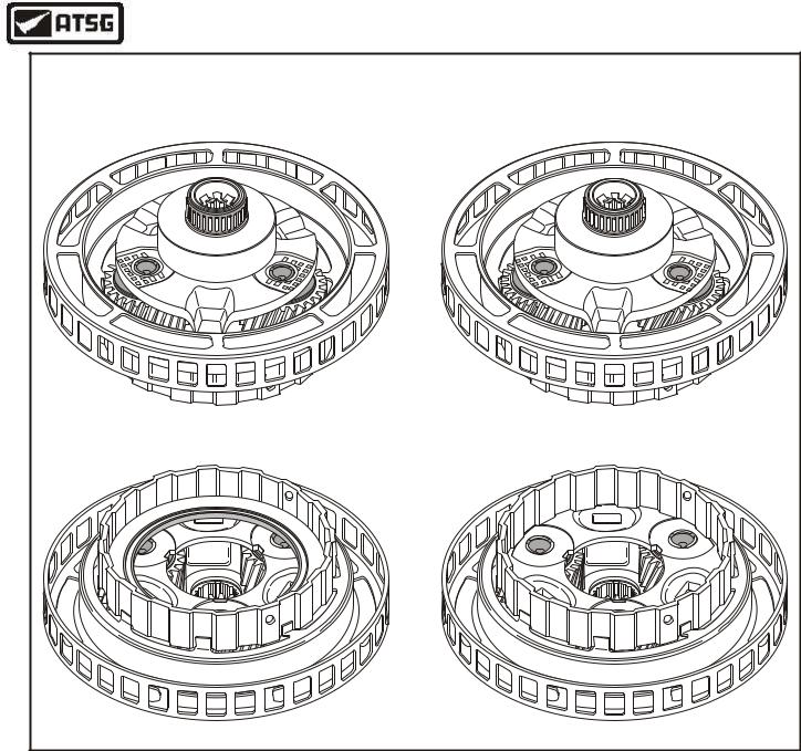
Caution: There are two different overdrive ratios for this unit, 0.75 and 0.71. This will affect the overdrive carrier, overdrive ring gear, overdrive sun gear, overdrive sun gear adapter plate and the coast clutch housing.
For overdrive planetary carrier identification refer to Figure 158.
For overdrive planetary ring gear identification refer to Figure 159.
For overdrive sun gear and sun gear adapter plate identification refer to Figure 160.
For the coast clutch housing identification refer to Figure 161.
NONE OF THE PARTS LISTED ABOVE ARE COMPATABLE WITH ONE ANOTHER
CENTER SHAFT |
THRUST BEARING |
(NO. 3) |
Copyright © 2004 ATSG |
Figure 156
44.Install the overdrive sun gear into overdrive carrier, as shown in Figure 157, by rotating into position.
45.Install the coast clutch housing adapter plate on overdrive sun gear, as shown in Figure 157, and ensure that it is fully seated.
Continued on Page 92
|
|
|
|
COAST CLUTCH |
|
X |
|
|
DRUM ADAPTER |
A |
W |
|||
|
4 |
|||
|
|
P |
||
4 |
|
|
-7 |
|
X |
|
|
6 |
|
4 |
|
|
6 |
|
B |
|
|
0 |
|
|
A |
A |
- |
|
|
|
|
||
|
|
|
|
OVERDRIVE |
|
|
|
|
SUN GEAR |
|
|
|
|
OVERDRIVE CARRIER |
|
|
|
|
AND CENTER SHAFT |
|
|
|
|
ASSEMBLY |
|
|
|
|
Copyright © 2004 ATSG |
Figure 157
88 |
AUTOMATIC TRANSMISSION SERVICE GROUP |
|
Technical Service Information
OVERDRIVE PLANETARY CARRIER |
|
0.75 Ratio Overdrive Carrier |
0.71 Ratio Overdrive Carrier |
25 Tooth Pinion Gears |
28 Tooth Pinion Gears |
|
Copyright © 2004 ATSG |
Figure 158
AUTOMATIC TRANSMISSION SERVICE GROUP |
89 |
|
Technical Service Information
OVERDRIVE INTERNAL RING GEAR
0.75 Ring Gear |
0.71 Ring Gear |
72 Teeth |
94 Teeth |
Snap Ring
Snap Ring
Thickness = .060"
Thickness = .050"
Width = .155"
Width = .194"
Copyright © 2004 ATSG
Figure 159
90 |
AUTOMATIC TRANSMISSION SERVICE GROUP |
|