

5R55W
.pdfTechnical Service Information
OIL PUMP ASSEMBLY (Cont'd)
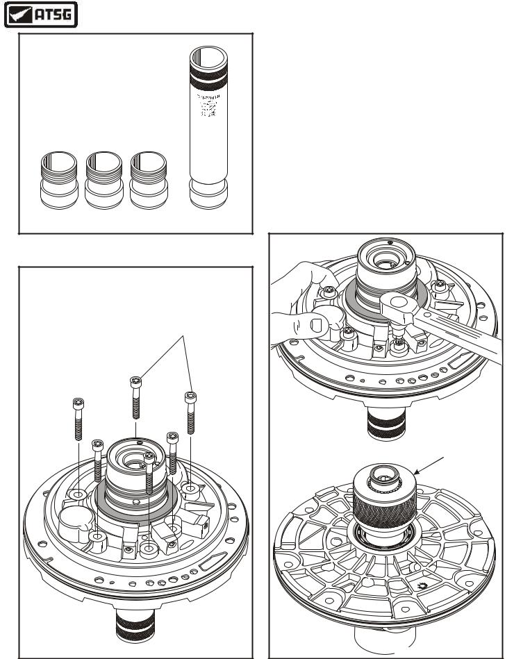
11.Install a new converter seal into the oil pump cover using the proper seal driver, as shown in Figure 61.
12.Install a new "D" ring seal into outer groove of the oil pump cover, as shown in Figure 61.
13.Lubricate both seals and bushing with a small amount of Trans-Jel®.
14.Place pump body and stator shaft assembly on bench with shaft facing up (See Figure 62).
Note: Ensure that the "O" ring seal is still in place on the relief valve (See Figure 62).
15.Install oil pump spacer plate and pump cover onto pump body, as shown in Figure 62.
Continued on Page 42
OIL PUMP |
|
CONVERTER |
|
HUB SEAL |
|
OIL PUMP |
|
COVER |
|
8 |
9 |
|
|
OIL PUMP |
|
"D" RING |
|
SEAL |
|
Copyright © 2004 ATSG |
|
|
OIL PUMP |
|
COVER |
|
ASSEMBLY |
8 |
9 |
|
|
|
OIL PUMP |
|
SPACER |
|
PUMP BODY |
|
ASSEMBLY |
|
Ensure "O" Ring |
|
Is In Place On |
|
Relief Valve |
Copyright © 2004 ATSG |
|
Figure 61 |
Figure 62 |
AUTOMATIC TRANSMISSION SERVICE GROUP |
41 |
|
Technical Service Information
Ford Motor Company
Pump Alignment Tool
(1) 307-S309
(1) 307-431
(1) 307-432
D C B A
Copyright © 2004 ATSG
Figure 63
|
|
|
|
|
|
|
|
|
|
|
|
|
PUMP BODY TO |
||
|
|
|
|
|
|
|
|
|
|
|
|
|
COVER BOLTS |
||
|
|
|
|
|
|
|
|
|
|
|
|
|
(6 REQUIRED) |
||
|
|
|
|
|
|
|
|
|
4 |
WX |
|
|
|
|
|
|
|
|
|
|
|
|
|
- |
P |
|
|
|
|
|
|
|
|
|
|
|
|
|
|
7 |
|
D |
|
|
|
|
|
|
|
|
|
|
|
|
|
D |
|
0 4 Y |
M |
|
|
|
|
|
|
|
|
|
|
|
0 |
|
|
A |
A 1 |
|
|
||
|
|
|
|
|
|
4 |
|
|
|
|
|
|
|
|
|
|
|
|
|
|
|
3 |
d |
|
|
|
|
|
|
|
|
|
|
|
|
|
|
r |
|
|
|
|
|
|
|
||
|
|
|
|
|
|
o |
|
|
|
|
|
|
|
|
|
|
|
|
|
|
G |
F |
|
|
|
|
|
|
|
|
|
|
|
F |
5 |
|
|
|
|
|
|
|
|
|
|
||
|
P |
|
|
|
|
|
|
|
|
|
|
|
|||
C |
|
|
|
|
|
|
|
|
|
|
|
|
|
||
|
|
|
|
|
|
|
|
|
|
|
|
|
|
||
|
|
|
|
|
|
|
|
|
|
|
|
|
|
|
|
|
|
|
|
|
|
|
|
|
|
|
|
|
|
|
d |
|
|
|
|
|
|
|
|
|
|
|
|
|
|
r |
|
|
|
|
|
|
|
|
|
|
|
|
|
|
o |
|
|
|
|
|
|
|
|
|
|
|
|
|
|
|
F |
|
|
A |
A- |
|
|
|
|
|
|
|
|
|
|
|
|
||
|
|
|
5 |
23 |
|
|
|
|
|
|
|
|
|
|
|
|
|
|
|
|
B |
|
|
|
|
|
|
|
|
|
|
|
|
|
|
|
|
7- |
|
|
|
|
|
|
|
|
|
|
|
|
|
|
|
P |
|
|
|
|
|
|
|
|
|
|
|
|
|
|
|
4 |
WX |
|
|
|
|
|
|
|
|
|
|
|
|
|
|
|
F |
|
|
|
|
|
|
|
|
|
|
|
|
|
|
|
|
R |
|
|
|
|
|
|
|
|
|
|
|
|
|
|
|
|
|
|
|
Copyright © 2004 ATSG |
|||
Figure 64
OIL PUMP ASSEMBLY (Cont'd)
16.Install the appropriate size sleeve into handle of Ford Motor Co.Pump Alignment Tools, shown in Figure 63, and install into pump.
17.Turn the assembly over and install the six bolts that retain the body to the cover, as shown in Figure 64.
18.With the alignment tool in place, torque all six bolts in a star pattern to 18 ft.lb. as shown in Figure 65.
19.Remove the alignment tool and ensure that the pump gears will turn after they are torqued, as shown in Figure 65.
20.Set the completed pump assembly aside for the final assembly process.
|
|
|
|
|
|
|
|
|
4 |
WX |
|
|
|
|
|
|
|
|
|
|
|
|
|
|
- |
P |
|
|
|
|
|
|
|
|
|
|
|
|
|
|
|
7 |
|
D |
|
|
|
|
|
|
|
|
|
|
|
|
|
|
D |
|
0 4 Y |
M |
|
|
|
|
|
|
|
|
|
|
|
|
0 |
|
|
A |
A 1 |
|
|
|
||
|
|
|
|
|
|
4 |
|
|
|
|
|
|
|
|
|
|
|
|
|
|
|
|
3 |
d |
|
|
|
|
|
|
|
|
|
|
|
|
|
|
|
r |
|
|
|
|
|
|
|
|
||
|
|
|
|
|
|
o |
|
|
|
|
|
|
|
|
|
|
|
|
|
|
|
G |
F |
|
|
|
|
|
|
|
|
|
|
|
|
F |
5 |
|
|
|
|
|
|
|
|
|
|
|
||
|
P |
|
|
|
|
|
|
|
|
|
|
|
|
|||
C |
|
|
|
|
|
|
|
|
|
|
|
|
|
|
||
|
|
|
|
|
|
|
|
|
|
|
|
|
|
|
||
|
|
|
|
|
|
|
|
|
|
|
|
|
|
|
|
|
|
|
|
|
|
|
|
|
|
|
|
|
|
|
|
|
d |
|
|
|
|
|
|
|
|
|
|
|
|
|
|
|
r |
|
|
|
|
|
|
|
|
|
|
|
|
|
|
|
o |
|
|
|
|
|
|
|
|
|
|
|
|
|
|
|
|
F |
|
|
A |
A- |
|
|
|
|
|
|
|
|
|
|
|
|
|
||
|
|
|
|
|
|
|
|
|
|
|
|
|
|
|||
|
|
|
5 |
23 |
|
|
|
|
|
|
|
|
|
|
|
|
|
|
|
|
|
B |
|
|
|
|
|
|
|
|
|
|
|
|
|
|
|
|
|
7- |
|
|
|
|
|
|
|
|
|
|
|
|
|
|
|
|
P |
|
|
|
|
|
|
|
|
|
|
|
|
|
|
|
|
4 |
WX |
|
|
|
|
|
|
|
|
|
|
|
|
|
|
|
|
F |
|
|
|
|
|
|
|
|
|
|
|
|
|
|
|
|
|
R |
|
|
|
|
|
|
|
|
|
|
|
|
|
|
|
|
|
|
|
|
ENSURE THAT GEARS |
||||
|
|
|
|
|
|
|
|
|
|
|
|
TURN AFTER TORQUE |
||||
|
|
|
|
|
|
|
|
|
|
|
|
|
8 |
9 |
|
|
|
|
|
|
|
|
|
|
|
|
|
|
|
|
|
|
|
|
|
|
|
|
|
|
|
|
|
|
Copyright © 2004 ATSG |
|||||
Figure 65
42 |
AUTOMATIC TRANSMISSION SERVICE GROUP |
|
Technical Service Information
COAST CLUTCH ASSEMBLY
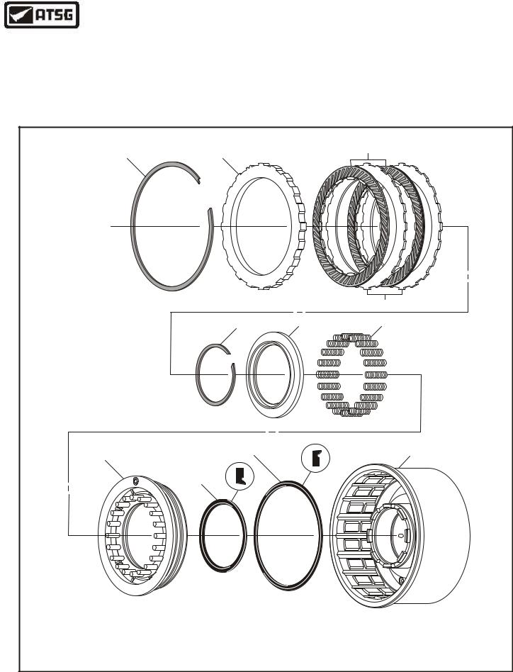
1.Disassemble the coast clutch assembly using the illustrations in Figure 66 as a guide.
2.Remove and discard the coast clutch lip seals, as shown in Figure 66.
3.Inspect all coast clutch parts thoroughly for any wear and/or damage.
4.Clean all coast clutch parts thoroughly and dry with compressed air.
Continued on Page 44
|
|
COAST CLUTCH EXPLODED VIEW |
|
|
|
1 |
2 |
3 |
|
|
|
|
||
|
Thickness = .065" |
|
|
|
|
Width = .155" |
|
|
|
|
|
|
|
4 |
|
|
5 |
6 |
7 |
|
8 |
10 |
|
11 |
|
|
|
|
|
|
8 |
9 |
|
|
|
|
|
|
|
1. |
COAST CLUTCH BACKING PLATE SNAP RING. |
|
7. COAST CLUTCH RETURN SPRINGS (20 REQUIRED). |
|
2. |
COAST CLUTCH BACKING PLATE. |
|
8. COAST CLUTCH PISTON. |
|
3. |
COAST CLUTCH FRICTION PLATES. |
|
9. COAST CLUTCH INNER LIP SEAL. |
|
4. |
COAST CLUTCH STEEL PLATES. |
|
10. COAST CLUTCH OUTER LIP SEAL. |
|
5. |
COAST CLUTCH SPRING RETAINER SNAP RING. |
|
11. COAST CLUTCH HOUSING. |
Copyright © 2004 ATSG |
6. |
COAST CLUTCH RETURN SPRING RETAINER. |
|
|
|
Figure 66
AUTOMATIC TRANSMISSION SERVICE GROUP |
43 |
|
Technical Service Information
COAST CLUTCH ASSEMBLY (Cont'd)
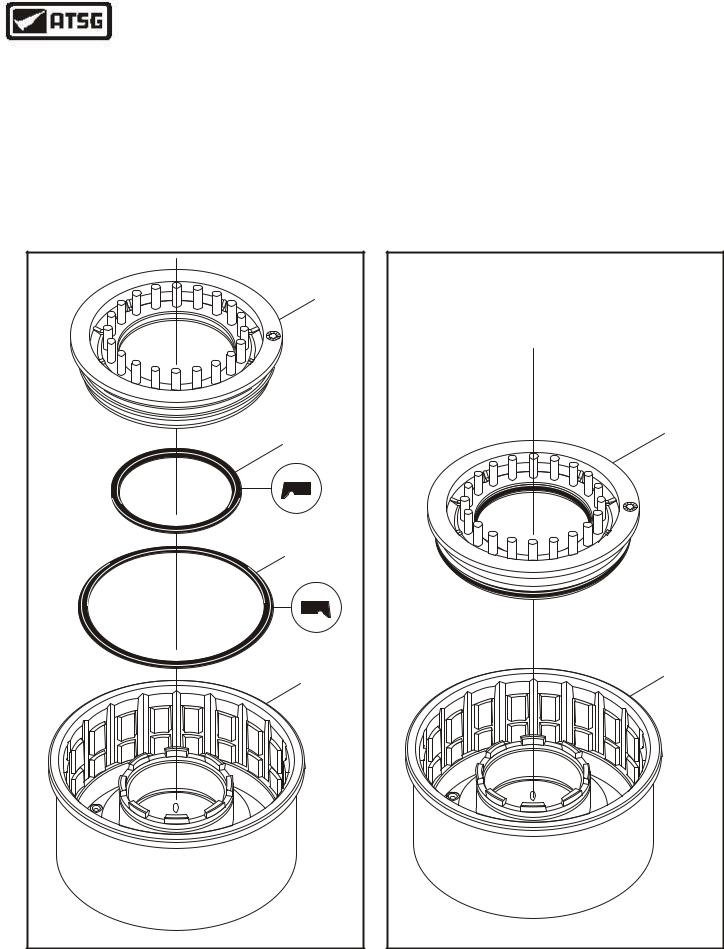
5.Install a new inner lip seal into the groove in the coast clutch piston, with the lip facing down, as shown in Figure 67.
6.Install a new outer lip seal into the groove in the coast clutch piston, with the lip facing down, as shown in Figure 67.
7.Lubricate both inner and outer lip seals with a small amount of Trans-Jel®.
8.Lubricate both the inner and outer seal surfaces in coast clutch housing with a small amount of Trans-Jel®.
9.Install the completed coast clutch piston into the overrun clutch housing with twisting motion, as shown in Figure 68.
Continued on Page 45
COAST |
CLUTCH |
PISTON |
8 |
COAST CLUTCH |
PISTON INNER |
LIP SEAL |
COAST CLUTCH |
PISTON OUTER |
LIP SEAL |
COAST CLUTCH |
HOUSING |
Copyright © 2004 ATSG |
Figure 67
COAST CLUTCH |
PISTON ASSEMBLY |
8 |
COAST CLUTCH |
HOUSING |
Copyright © 2004 ATSG |
Figure 68
44 |
AUTOMATIC TRANSMISSION SERVICE GROUP |
|

Technical Service Information
COAST CLUTCH
RETURN SPRING
RETAINER SNAP RING
COAST CLUTCH RETURN SPRING  RETAINER
COAST CLUTCH
PISTON RETURN  SPRINGS (20)
COAST CLUTCH ASSEMBLY (Cont'd)
10.Install the coast clutch piston return springs on the coast clutch piston, as shown in Figure 69.
11.Install the coast clutch return spring retainer on top of return springs, as shown in Figure 69.
12.Carefully compress the retainer and the return springs and install the retaining snap ring, as shown in Figure 69.
13.Remove the spring compressor and ensure that everything is fully seated.
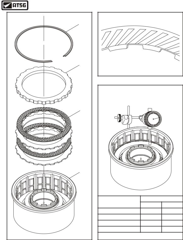
14.Install the friction and steel coast clutch plates into the coast clutch drum, beginning with a steel plate and alternating with a friction plate, until you have installed two of each, as shown in Figure 70.
CAUTION: Coast Clutch friction plates are directional and must be installed with the grooves facing clockwise, as shown in Figures 70 and 71. Friction plates should be soaked in Mercon® V for at least 30 minutes before installation.
15.Install the coast clutch backing plate, as shown in Figure 70.
16.Install the coast clutch backing plate snap ring, as shown in Figure 70 and ensure that it is fully seated in the groove (See Figure 70).
17.Install dial indicator on top of backing plate, as shown in Figure 72, and check the coast clutch clearance. Should be 1.3-2.0mm (.051"-.079"), as shown in Figure 72.
18.Change the selective backing plate snap ring as necessary, using the chart in Figure 72, to get the proper clutch clearance.
19.Set the completed coast clutch housing aside for the final assembly process.
8
Copyright © 2004 ATSG
Figure 69
AUTOMATIC TRANSMISSION SERVICE GROUP |
45 |
|
Technical Service Information
COAST CLUTCH |
BACKING PLATE |
SNAP RING |
"Selective" Snap Ring |
COAST CLUTCH |
BACKING PLATE |
COAST CLUTCH |
LINED AND STEEL |
COAST CLUTCH |
HOUSING |
8 |
Copyright © 2004 ATSG |
COAST CLUTCH
PATTERN DIRECTION
CAUTION: Coast Clutch friction plates are directional and must be installed with the grooves facing clockwise, as shown above.
Figure 71
CHECKING COAST CLUTCH CLEARANCE |
|||
CLEARANCE SHOULD BE 1.3 - 2.0mm (.051"-.079") |
|||
|
10 |
0 |
10 |
|
|
||
|
20 |
|
20 |
|
30 |
|
30 |
|
40 |
|
40 |
|
50 |
0 |
50 |
|
|
|
8 |
|
|
Thickness |
|
Part Number |
mm |
in |
|
E860126-S |
1.37 |
.054" |
|
E860127-S |
1.73 |
.068" |
|
E860128-S |
2.08 |
.082" |
|
E860129-S |
2.44 |
.096" |
|
|
Copyright © 2004 ATSG |
||
Figure 70 |
Figure 72 |
46 |
AUTOMATIC TRANSMISSION SERVICE GROUP |
|
Technical Service Information
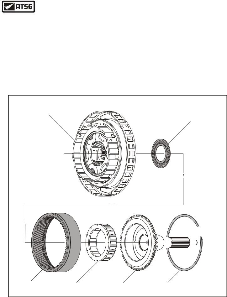
OVERDRIVE CARRIER AND SPRAG ASSEMBLY
1.Disassemble the overdrive carrier from center shaft using Figure 73 as a guide.
2.Inspect all of the overdrive carrier parts shown in Figure 73 for any wear and/or damage.
3.Clean all overdrive carrier parts thoroughly and dry with compressed air.
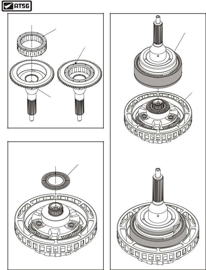
4.Install the overdrive sprag assembly into the overdrive center shaft, in the direction shown in Figure 74, until fully seated.
5.Install thrust bearing onto overdrive carrier, as shown in Figure 75, and retain with a small amount of Trans-Jel®.
6.Install completed overdrive center shaft onto the overdrive carrier by rotating shaft counter clockwise as you install (See Figure 76).
7.Verify proper overdrive sprag rotation, using Figure 76, and then set the overdrive planetary carrier assembly aside for final assembly.
Continued on Page 48
|
OVERDRIVE CARRIER/SPRAG EXPLODED VIEW |
|||
OVERDRIVE PLANETARY |
|
OVERDRIVE PLANETARY |
||
CARRIER ASSEMBLY |
|
|
||
|
|
CARRIER TO CENTER SHAFT |
||
|
|
|
||
|
|
|
THRUST BEARING |
|
OVERDRIVE |
OVERDRIVE |
OVERDRIVE |
CENTER SHAFT TO |
|
RING GEAR |
||||
SPRAG ASSEMBLY |
CENTER SHAFT |
RING GEAR SNAP RING |
||
|
||||
|
|
|
Copyright © 2004 ATSG |
|
Figure 73
AUTOMATIC TRANSMISSION SERVICE GROUP |
47 |
|
Technical Service Information
OVERDRIVE SPRAG |
ASSEMBLY |
ENSURE THAT SPRAG |
IS FULLY SEATED |
OVERDRIVE |
CENTER SHAFT |
Copyright © 2004 ATSG |
Figure 74
CENTER SHAFT TO |
CARRIER THRUST BEARING |
Copyright © 2004 ATSG |
COMPLETED CENTER |
SHAFT AND RING |
GEAR ASSEMBLY |
OVERDRIVE CARRIER |
ASSEMBLY |
VIEWED FROM CENTER SHAFT SIDE |
Center Shaft Must Freewheel |
"Counter-Clockwise" While Holding |
The Overdrive Carrier |
FREEWHEEL |
Copyright © 2004 ATSG |
Figure 75 |
Figure 76 |
48 |
AUTOMATIC TRANSMISSION SERVICE GROUP |
|
Technical Service Information
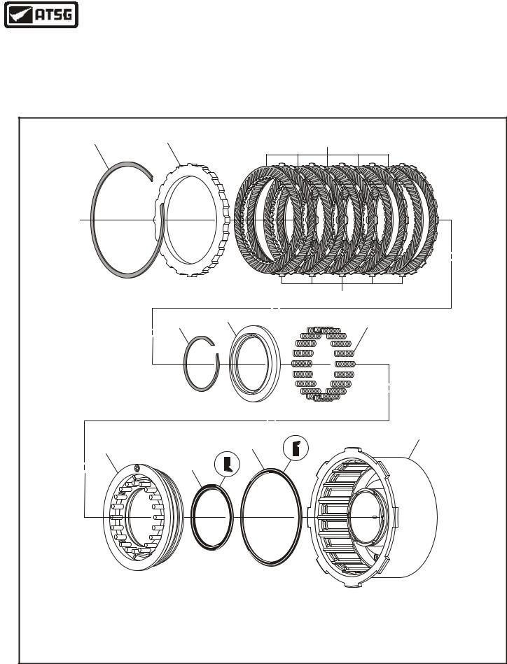
DIRECT CLUTCH ASSEMBLY
1.Disassemble the direct clutch assembly using the illustrations in Figure 77 as a guide.
2.Remove and discard the direct clutch lip seals, as shown in Figure 77.
3.Inspect all direct clutch parts thoroughly for any wear and/or damage.
4.Clean all direct clutch parts thoroughly and dry with compressed air.
Continued on Page 50
|
|
DIRECT CLUTCH EXPLODED VIEW |
|
|
1 |
2 |
3 |
|
|
|
4 |
|
|
5 |
6 |
|
|
7 |
|
|
|
|
11 |
|
8 |
|
10 |
|
|
|
|
|
8 |
9 |
|
1. |
DIRECT CLUTCH BACKING PLATE "SELECTIVE" SNAP RING. |
7. DIRECT CLUTCH RETURN SPRINGS (20 REQUIRED). |
|
2. |
DIRECT CLUTCH BACKING PLATE. |
|
8. DIRECT CLUTCH PISTON. |
3. |
DIRECT CLUTCH "SINGLE SIDED" INSIDE SPLINE PLATES. |
9. DIRECT CLUTCH INNER LIP SEAL. |
|
4. |
DIRECT CLUTCH "SINGLE SIDED" OUTSIDE SPLINE PLATES. |
10. DIRECT CLUTCH OUTER LIP SEAL. |
|
5. |
DIRECT CLUTCH SPRING RETAINER SNAP RING. |
11. DIRECT CLUTCH HOUSING. |
|
6. |
DIRECT CLUTCH RETURN SPRING RETAINER. |
Copyright © 2004 ATSG |
|
Figure 77
AUTOMATIC TRANSMISSION SERVICE GROUP |
49 |
|
Technical Service Information
DIRECT CLUTCH ASSEMBLY (Cont'd)
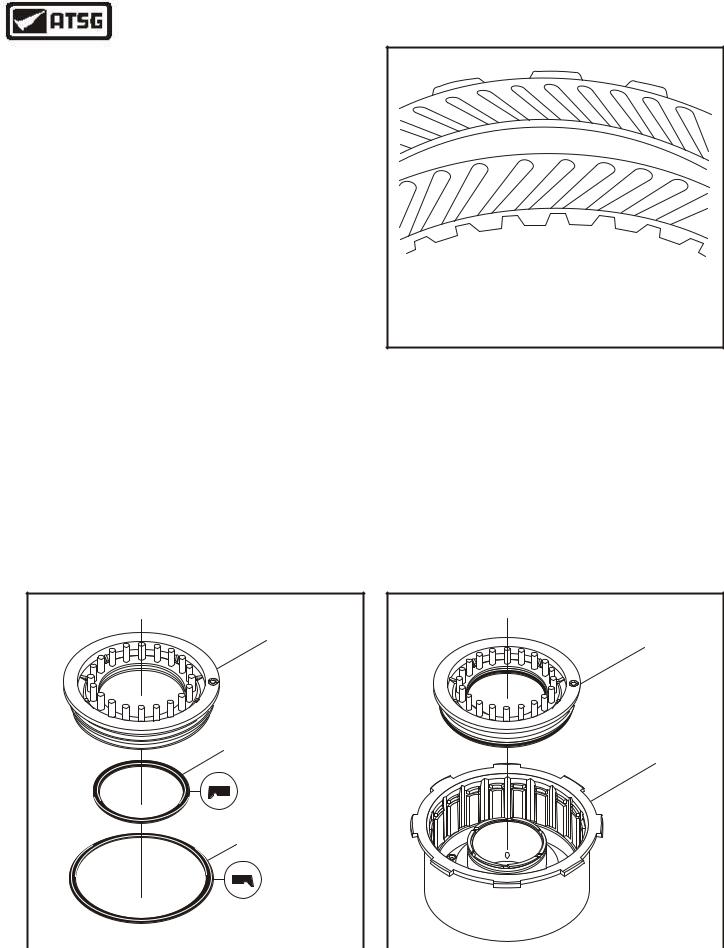
5.Install a new inner lip seal into the groove in the direct clutch piston, with the lip facing down, as shown in Figure 78.
6.Install a new outer lip seal into the groove in the direct clutch piston, with the lip facing down, as shown in Figure 78.
7.Lubricate both inner and outer lip seals with a small amount of Trans-Jel®.
8.Lubricate both the inner and outer seal surfaces in direct clutch housing with a small amount of Trans-Jel®.
9.Install the completed direct clutch piston into
the direct clutch housing with twisting motion, as shown in Figure 80.
10.Install the direct clutch piston return springs on the direct clutch piston, as shown in Figure 81.
11.Install the direct clutch return spring retainer on top of return springs, as shown in Figure 81.
12.Carefully compress the retainer and the return springs and install the retaining snap ring, as shown in Figure 81.
13.Remove the spring compressor and ensure that everything is fully seated.
CAUTION: Direct Clutch friction plates are directional and must be installed with the internal tooth plate grooves facing clockwise, and the external tooth plates grooves facing counterclockwise, as shown in Figure 79.
DIRECT CLUTCH PATTERN DIRECTION |
CAUTION: Direct Clutch friction plates are |
directional and must be installed with the internal |
tooth plate grooves facing clockwise, and the |
e x t e r n a l t o o t h p l a t e s g r o o v e s f a c i n g |
counterclockwise, as shown above. |
Figure 79
14.Install the direct clutches beginning with an outside spline plate and alternating with inside spline plates, until you have installed 5 of each, as shown in Figure 82.
Caution: Friction plates should be soaked in Mercon® V, 3o minutes before installing.
Continued on Page 51
DIRECT CLUTCH
DIRECT CLUTCH
PISTON
PISTON ASSEMBLY
8
8
DIRECT CLUTCH PISTON
DIRECT CLUTCH
INNER LIP SEAL
HOUSING
DIRECT CLUTCH PISTON
OUTER LIP SEAL
Copyright © 2004 ATSG |
|
Copyright © 2004 ATSG |
Figure 78 |
|
Figure 80 |
50 |
AUTOMATIC TRANSMISSION SERVICE GROUP |
|