

5R55W
.pdfTechnical Service Information
INTERNAL COMPONENTS (Cont'd)
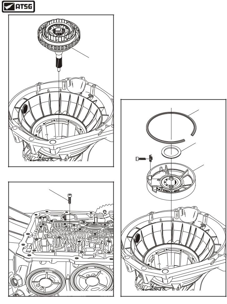
29.Using the special pump rmoval tool and your slide hammer, remove the oil pump assembly, as shown in Figure 36.
30.Set the oil pump assembly aside for component rebuild section in this manual.
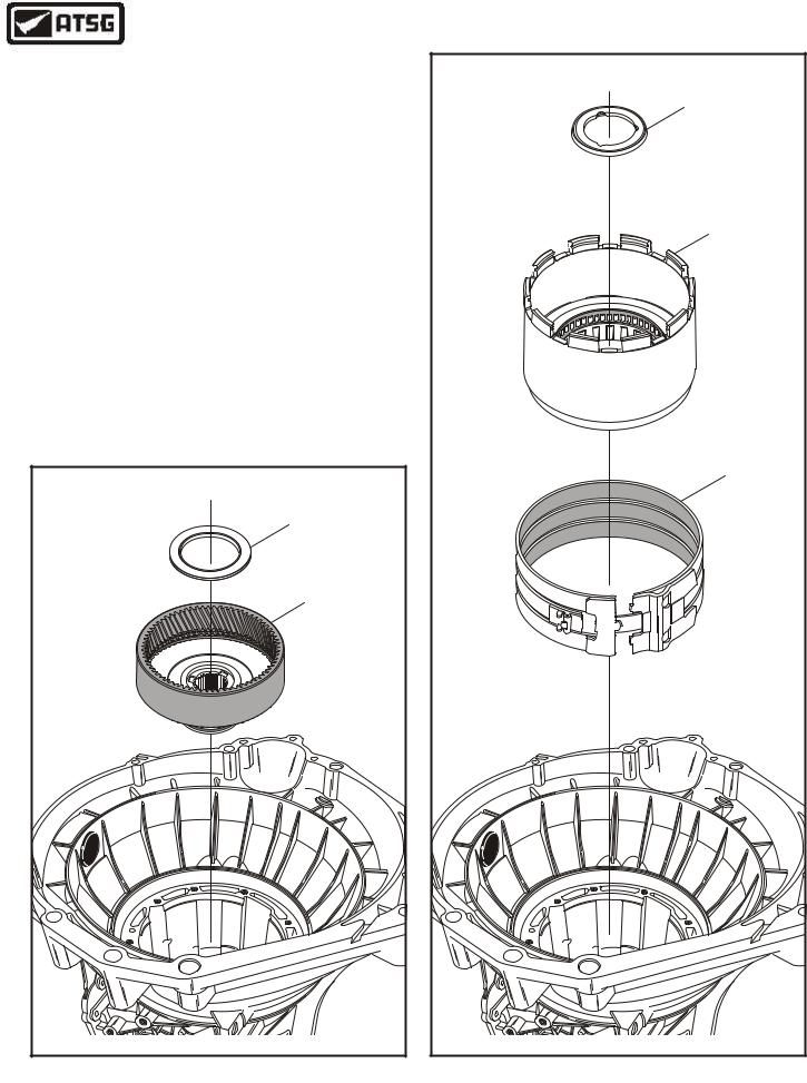
31.Remove the OD/Coast clutch drum assembly, as shown in Figure 37, and set drum aside for the component rebuild section.
32.Remove the overdrive band assembly and both band struts, as shown in Figure 38.
Note: Notice the difference in the band struts and which side they are located, as shown in Figure 38.
33.Remove the coast clutch drum adapter and the overdrive sun gear from the overdrive carrier, as shown in Figure 39.
Continued on Page 32
COAST CLUTCH |
DRUM ASSEMBLY |
9 |
9 |
/ |
1 |
0 |
/ |
9 |
0 |
B |
A |
- |
9 |
6 |
6 |
L |
7 |
P- |
4 |
W |
X |
Copyright © 2004 ATSG |
Figure 37
|
OVERDRIVE |
|
BAND |
BAND STRUT |
BAND STRUT |
SERVO SIDE |
ADJUST SIDE |
|
Copyright © 2004 ATSG |


 Figure 38

|
|
|
|
COAST CLUTCH |
|
X |
|
|
DRUM ADAPTER |
A |
W |
|||
|
4 |
|||
|
|
P |
||
4 |
|
|
- |
|
|
|
7 |
||
X |
|
|
6 |
|
4 |
|
|
6 |
|
B |
|
|
0 |
|
|
A |
A |
- |
|
|
|
|
||
|
|
|
|
OVERDRIVE |
|
|
|
|
SUN GEAR |
|
|
|
|
Copyright © 2004 ATSG |
Figure 39
AUTOMATIC TRANSMISSION SERVICE GROUP |
31 |
|
Technical Service Information
OVERDRIVE CARRIER |
AND CENTER SHAFT |
ASSEMBLY |
Copyright © 2004 ATSG |
Figure 40
CENTER SUPPORT |
|
|
|
|
|
|
|
|
|
RETAINING BOLT |
|
|
|
|
|
|
|
|
|
(20mm LENGTH) |
|
|
|
|
|
|
|
|
|
S |
F |
|
|
|
|
|
DA |
||
A |
|
|
o |
|
|
|
|
||
|
|
|
r |
|
|
|
|||
G |
|
|
|
|
d |
R3 |
|
||
|
|
|
|
|
|
|
6 |
8 |
|
|
|
|
|
|
|
|
T |
538 |
|
|
|
|
|
|
|
|
9 |
|
|
|
|
|
0 |
|
A |
A |
|
|
|
|
|
4 |
|
|
|
|
|
||
|
5 |
|
9 |
|
|
F |
|||
|
6 |
|
|
|
|
|
|||
|
|
|
1 |
|
|
|
|||
|
|
3 |
|
|
|
|
|
dro |
|
|
R |
|
|
|
|
Copyright © 2004 ATSG |
|||
|
|
|
|
|
|
|
|||
Figure 41
INTERNAL COMPONENTS (Cont'd)
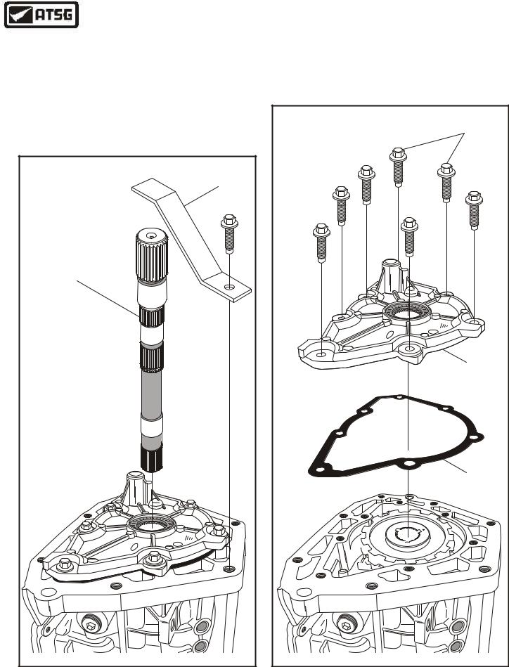
34.Remove the overdrive carrier and center shaft assembly, as shown in Figure 40.
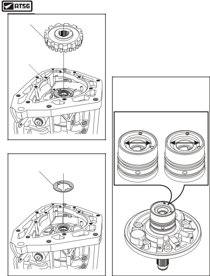
35.Now, remove the center support retaining bolt from the case, as shown in Figure 41, and also remove the locknut, as shown in Figure 42, to prevent it from falling into the assembly.
36.Remove the center support retaining snap ring from the case, as shown in Figure 42.
37.Remove center shaft thrust bearing (No. 3) from the center support, as shown in Figure 42 and tag it for I.D. and location.
Continued on Page 33
CENTER SUPPORT |
"TAPERED" |
SNAP RING |
CENTER SHAFT |
THRUST BEARING |
(NO. 3) |
CENTER SUPPORT |
ASSEMBLY |
96 |
M 07 |
1624 |
Copyright © 2004 ATSG |
Figure 42
32 |
AUTOMATIC TRANSMISSION SERVICE GROUP |
|
Technical Service Information
INTERNAL COMPONENTS (Cont'd)
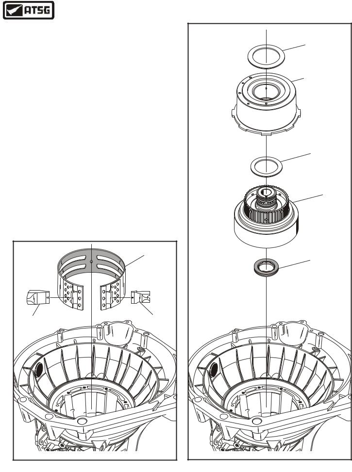
38.Remove the center support and set aside for component rebuild, as shown in Figure 43.
39.Remove the intermediate band assembly and both band struts, as shown in Figure 43.
Note: Notice the difference in the band struts and which side they are located, as shown in Figure 43.
40.Remove and tag for I.D. direct clutch (No. 4) selective thrust bearing, as shown in Figure 44.
41.Remove the direct clutch housing assembly and set aside for component rebuild, as shown in Figure 44.
42.Remove and tag for I.D. forward clutch (No. 5) thrust bearing, as shown in Figure 44.
43.Remove the forward clutch housing assembly and set aside for component rebuild, as shown Figure 44.
44.Remove and tag for I.D. the forward clutch (No. 6A) thrust bearing (See Figure 44).
Note: This bearing may stick to the forward clutch housing during removal.
Continued on Page 34
|
INTERMEDIATE |
|
BAND |
BAND STRUT |
BAND STRUT |
SERVO SIDE |
ADJUST SIDE |
|
Copyright © 2004 ATSG |
Figure 43
DIRECT CLUTCH |
"SELECTIVE" |
THRUST BEARING |
(NO. 4) |
DIRECT CLUTCH |
DRUM ASSEMBLY |
FORWARD CLUTCH |
THRUST BEARING |
(NO. 5) |
FORWARD CLUTCH |
DRUM ASSEMBLY |
FORWARD CLUTCH |
THRUST BEARING |
(NO. 6A) |
Copyright © 2004 ATSG |
Figure 44
AUTOMATIC TRANSMISSION SERVICE GROUP |
33 |
|
Technical Service Information
INTERNAL COMPONENTS (Cont'd)
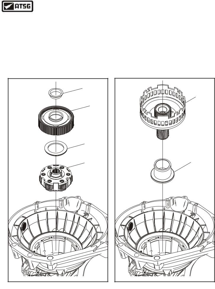
45.Remove forward ring gear and hub assembly along with the forward clutch (No. 6B) thrust washer, as shown in Figure 45.
46.Remove and tag for I.D. the forward planet (No. 7) thrust bearing (See Figure 45).
Note: Bearing may come out with the forward ring gear and hub assembly.
47.Remove the forward planetary carrier assembly as shown in Figure 45, and set aside for the component rebuild section.
48.Remove the input sun gear and shell assembly, as shown in Figure 46.
49.Remove the low/reverse bearing spacer from transmission case, as shown in Figure 46.
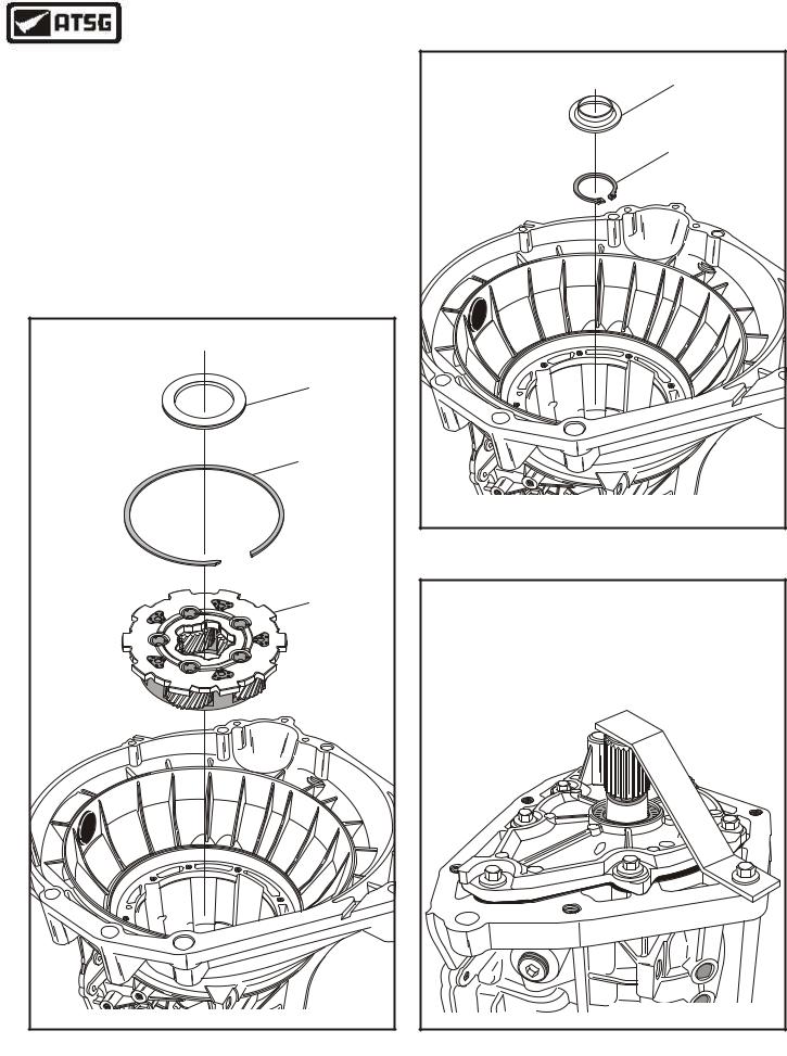
50.Remove and tag for I.D. the rear planetary thrust bearing (No. 8), as shown in Figure 47.
51.Remove the rear planetary retaining snap ring from reverse drum, as shown in Figure 47.
Continued on Page 35
|
|
FORWARD CLUTCH |
|
|
THRUST WASHER |
|
|
(NO. 6B) |
|
|
FORWARD RING |
|
|
GEAR AND HUB |
|
|
FORWARD PLANET |
|
|
THRUST BEARING |
|
|
(NO. 7) |
|
|
FORWARD PLANET |
D1 E4A |
|
ASSEMBLY |
A |
|
|
C |
|
o F |
-5 |
|
|
5 |
d r |
|
0 |
|
|
D |
|
|
P4 WXFR |
|
|
|
Copyright © 2004 ATSG |
|
Figure 45
INPUT SUN SHELL |
AND SUN GEAR |
"TALL" |
LOW/REVERSE |
SPACER |
Copyright © 2004 ATSG |
Figure 46
34 |
AUTOMATIC TRANSMISSION SERVICE GROUP |
|
Technical Service Information
INTERNAL COMPONENTS (Cont'd)
52.Remove the rear planetary carrier from the reverse drum, as shown in Figure 47.
53.Remove the plastic lube dam from the rear planetary ring gear, as shown in Figure 48.
54.Remove the output shaft retaining snap ring from the output shaft, as shown in Figure 48.
Caution: Install temporary strap on back of case, as shown in Figure 49, to retain the output shaft from falling out, "before" you remove the snap ring.
Continued on Page 36
REAR PLANETARY |
THRUST BEARING |
(NO. 8) |
REAR PLANETARY |
SNAP RING |
REAR PLANETARY |
ASSEMBLY |
Copyright © 2004 ATSG |
Figure 47
REAR LUBE DAM |
OUTPUT SHAFT |
SNAP RING |
Copyright © 2004 ATSG |
Figure 48
CAUTION: INSTALL TEMPORARY |
||||||||||||||
HOLDING STRAP AS SHOWN TO |
||||||||||||||
RETAIN OUTPUT SHAFT. |
||||||||||||||
|
|
|
|
|
|
|
|
P |
2 |
L |
1 |
|
|
F |
|
|
|
|
|
|
7 |
- |
|
|
o |
||||
|
|
|
|
|
A |
|
|
r |
||||||
|
|
|
|
0 |
|
|
d |
|||||||
|
|
- 9 |
3 |
|
|
|
|
|
|
|||||
|
|
|
|
|
|
|
|
|
|
|||||
|
B |
|
|
|
|
|
|
|
|
|
|
|||
A |
|
|
|
|
|
|
|
|
|
|
|
|||
|
|
|
|
|
|
|
|
|
|
|
|
|||
|
|
|
|
|
|
|
|
|
|
|
|
|
||
|
|
|
|
|
|
|
|
|
|
|
|
|
|
|
|
|
|
|
|
|
|
|
|
|
|
|
|
|
Copyright © 2004 ATSG |
Figure 49
AUTOMATIC TRANSMISSION SERVICE GROUP |
35 |
|
Technical Service Information
INTERNAL COMPONENTS (Cont'd)
55.Remove and tag for identification, the rear ring gear (No. 9) thrust bearing (See Figure 50).
56.Remove the rear planetary ring gear from the transmission, as shown in Figure 50.
57.Remove reverse drum and low sprag assembly by rotating and lifting drum out, as shown in Figure 51.
58.Remove and tag for I.D. the rear planetary gear thrust bearing (No. 10), as shown in Figure 51.
59.Remove the low/reverse band assembly from the case, as shown in Figure 51.
60.Rotate the transmission so that output shaft is facing up, as shown in Figure 52.
Continued on Page 37
REAR PLANETARY |
RING GEAR THRUST |
BEARING (NO. 9) |
REAR PLANETARY |
RING GEAR |
Copyright © 2004 ATSG |
Figure 50
REAR PLANETARY |
RING GEAR THRUST |
BEARING (NO. 10) |
REVERSE DRUM |
AND LOW SPRAG |
ASSEMBLY |
LOW/REVERSE |
BAND ASSEMBLY |
Copyright © 2004 ATSG |
Figure 51
36 |
AUTOMATIC TRANSMISSION SERVICE GROUP |
|
Technical Service Information
INTERNAL COMPONENTS (Cont'd)
61.Remove the temporary retaining bracket and the output shaft, as shown in Figure 52.
62.Remove the seven retaining bolts from 4WD adapter, as shown in Figure 53.
63.Remove the 4WD adapter housing, as shown in Figure 53, and set aside for the component rebuild section.
|
|
|
|
|
|
|
|
|
|
|
|
|
|
TEMPORARY |
|
|
|
|
|
|
|
|
|
|
|
|
|
|
BRACKET |
OUTPUT SHAFT |
|
|
|
|
|
|
|
|
|
|
|
|
|
|
(4WD VERSION SHOWN) |
|
|
|
|
|
|
|
|
|
|
|
|
|
|
|
|
|
|
|
|
|
|
P |
2 |
L |
1 |
|
|
F |
|
|
|
|
|
|
7 |
- |
|
|
o |
||||
|
|
|
|
|
A |
|
|
r |
||||||
|
|
|
|
0 |
|
|
d |
|||||||
|
|
|
|
|
|
|
||||||||
|
|
- 9 |
3 |
|
|
|
|
|
|
|||||
|
|
|
|
|
|
|
|
|
|
|||||
|
B |
|
|
|
|
|
|
|
|
|
|
|||
A |
|
|
|
|
|
|
|
|
|
|
|
|||
|
|
|
|
|
|
|
|
|
|
|
|
|||
|
|
|
|
|
|
|
|
|
|
|
|
|
||
|
|
|
|
|
|
|
|
|
|
|
|
|
|
|
|
|
|
|
|
|
|
|
|
|
|
|
|
|
Copyright © 2004 ATSG |
Figure 52
64.Remove and discard the 4WD adapter housing gasket, as shown in Figure 53.
Continued on Page 38
|
|
|
|
|
|
|
|
|
|
|
|
|
|
RETAINING BOLTS |
|
|
|
|
|
|
|
|
|
|
|
|
|
|
(7 REQUIRED) |
|
|
|
|
|
|
|
|
P |
2 |
L |
1 |
|
|
F |
|
|
|
|
|
|
7 |
- |
|
|
o |
||||
|
|
|
|
|
A |
|
|
r |
||||||
|
|
|
|
0 |
|
|
d |
|||||||
|
|
|
|
|
|
|
||||||||
|
|
- 9 |
3 |
|
|
|
|
|
|
|||||
|
|
|
|
|
|
|
|
|
|
|||||
|
B |
|
|
|
|
|
|
|
|
|
|
|||
A |
|
|
|
|
|
|
|
|
|
|
|
|||
|
|
|
|
|
|
|
|
|
|
|
|
|||
|
|
|
|
|
|
|
|
|
|
|
|
|
||
|
|
|
|
|
|
|
|
|
|
|
|
|
|
|
|
|
|
|
|
|
|
|
|
|
|
|
|
|
4WD ADAPTER |
|
|
|
|
|
|
|
|
|
|
|
|
|
|
HOUSING |
|
|
|
|
|
|
|
|
|
|
|
|
|
|
EXTENSION |
|
|
|
|
|
|
|
|
|
|
|
|
|
|
GASKET |
|
|
|
|
|
|
|
|
|
|
|
|
|
|
Copyright © 2004 ATSG |
Figure 53
AUTOMATIC TRANSMISSION SERVICE GROUP |
37 |
|
Technical Service Information
PARK GEAR |
NUMBER ELEVEN |
THRUST WASHER |
Copyright © 2004 ATSG |
Figure 54
INTERNAL COMPONENTS (Cont'd)
65.Remove the park gear, as shown in Figure 54.
66.Remove and tag for I.D. the park gear thrust washer (No. 11), as shown in Figure 55.
67.This completes transmission disassembly.
If replacement of the pump support assembly becomes necessary, ensure that replacement part has correct diameter recess for clearance of the different diameter O.D. sun gears, as shown below.
38 MM |
46 MM |
(0.75 Ratio) |
(0.71 Ratio) |
NUMBER ELEVEN
THRUST WASHER
C
Copyright © 2004 ATSG
|
4 |
WX |
- |
P |
|
7 |
|
|
D |
|
|
0 |
|
|
4 |
|
|
3 |
|
|
|
F |
5 |
G |
P |
|
||
|
|
||
|
|
|
|
|
d |
|
r |
|
o |
|
|
F |
|
|
Copyright © 2004 ATSG
Figure 55 |
Figure 56 |
38 |
AUTOMATIC TRANSMISSION SERVICE GROUP |
|
Technical Service Information
COMPONENT REBUILD SECTION
OIL PUMP ASSEMBLY
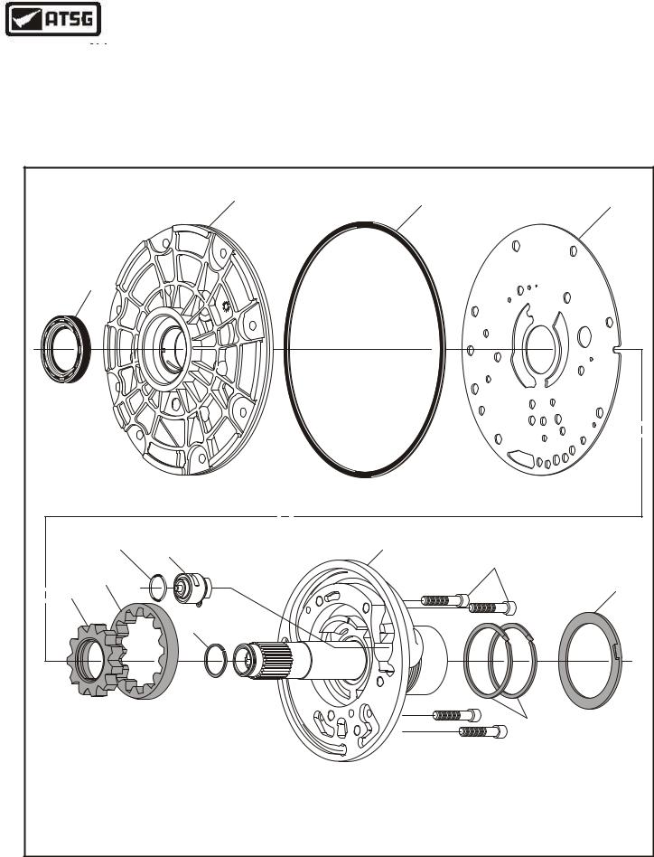
1.Disassemble the oil pump assembly using the illustrations in Figure 57 as a guide.
2.Remove and discard the converter seal and all sealing rings (See Figure 57).
3.Inspect all oil pump parts thoroughly for any wear and/or damage. Note: If replacement of pump support is necessary, see Figure 56.
4.Clean all oil pump and cover parts throughly and dry with compressed air
Continued on Page 40
OIL PUMP ASSEMBLY EXPLODED VIEW
2 |
3 |
4 |
|
1
9  8
8
Relief Valve |
|
"O" Ring |
9 |
7
10
6
12
5
8
11
1. |
FRONT PUMP OIL SEAL. |
7. |
LINE PRESSURE RELIEF VALVE ASSEMBLY. |
2. |
FRONT PUMP COVER. |
8. |
FRONT PUMP STATOR SHAFT SEAL RING (BUTT-CUT). |
3. |
FRONT PUMP COVER "D" RING SEAL. |
9. |
FRONT PUMP BODY AND STATOR ASSEMBLY. |
4. |
FRONT PUMP SPACER PLATE. |
10. |
FRONT PUMP BODY TO COVER BOLTS (6 REQUIRED). |
5. |
FRONT PUMP INNER GEAR. |
11. |
OVERRUN CLUTCH SEAL RINGS. |
6. |
FRONT PUMP OUTER GEAR. |
12. |
SELECTIVE THRUST WASHER (FRONT CLEARANCE) |
Figure 57
AUTOMATIC TRANSMISSION SERVICE GROUP |
39 |
|
Technical Service Information
OIL PUMP ASSEMBLY (Cont'd)
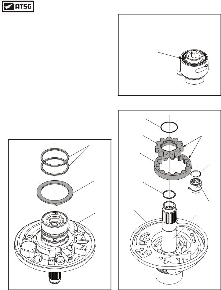
5.Install selective thrust washer that came with the unit and retain with Trans-Jel®, as shown in Figure 58.
6.Install the two overrun clutch seal rings into their grooves and insure that the scarf cuts are assembled properly (See Figure 58).
7.Install a new "O" ring on the inside diameter of the inner pump gear and ensure that it is fully seated in the groove (See Figure 60). Lube with a small amount of Trans-Jel®.
8.Dip the pump gears into transmission fluid and install them with the "Dots" facing down, as shown in Figure 60.
Caution: The pump gears must be installed with the "Dots" facing down (See Figure 60).
9.Install a new "Solid" seal ring in the groove
in the stator shaft, as shown in Figure 60.
10.Install the line pressure relief valve into the cavity in the pump, as shown in Figure 60.
Caution: See Note In Figure 59.
|
|
|
|
|
|
|
|
SEAL RINGS |
|
|
|
|
|
|
|
|
SELECTIVE |
|
|
|
|
|
|
|
|
THRUST WASHER |
|
|
|
|
|
|
|
|
PUMP BODY |
|
|
|
|
|
4 |
WX |
|
|
|
|
|
|
- |
P |
|
|
|
|
|
|
|
7 |
|
|
|
|
|
|
|
|
D |
|
|
|
|
|
|
|
|
0 |
|
|
|
|
|
|
|
|
4 |
|
|
|
|
|
|
|
|
3 |
|
|
|
|
|
|
F |
5 |
G |
|
|
|
|
|
P |
|
|
|
|
|
||
C |
|
|
|
|
|
|
||
|
|
|
|
|
|
|
||
|
|
|
|
|
|
|
|
|
|
|
|
|
|
|
|
|
d |
|
|
|
|
|
|
|
r |
|
|
|
|
|
|
|
o |
|
|
|
|
|
|
|
|
F |
|
|
|
|
|
|
|
|
Copyright © 2004 ATSG |
||
Figure 58
CAUTION: The Pump Relief Valve
Assembly "Must" Have The "O" Ring
In Place As Shown Below
"O" RING IN PLACE ON RELIEF VALVE 
Copyright © 2004 ATSG
Figure 59
INNER PUMP |
|
GEAR "O" RING |
CAUTION: |
|
|
|
Install Pump Gears |
INNER PUMP |
With "Dots" Facing |
Down |
|
GEAR |
|
OUTER PUMP |
|
GEAR |
|
|
RELIEF VALVE |
|
"O" RING |
"SOLID" |
|
SEAL RING |
|
FOR TCC |
|
|
LINE PRESSURE |
PUMP BODY |
RELIEF VALVE |
|
ASSEMBLY |
|
Copyright © 2004 ATSG |
Figure 60
40 |
AUTOMATIC TRANSMISSION SERVICE GROUP |
|