

5R55W
.pdfTechnical Service Information
|
|
SFT |
1 |
|
|
8.8 |
|
|
|
|
|
|
|
SFT |
|
|
|
8.8 |
|
SFT |
|
|
|
8.8 |
|
|
|
|
|
|
SFT |
|
|
|
8.8 |
SFT |
|
|
|
8.8 |
|
|
|
|
|
SFT |
|
|
|
8.8 |
|
SFT |
|
|
|
8.8 |
|
|
|
|
1 |
|
|
|
L |
|
|
® |
2 |
|
|
P |
rdFo |
|
|
- |
|
||
|
7 |
|
|
|
A |
|
|
|
0 |
|
|
|
3 |
|
|
|
8 |
|
|
|
- |
|
|
|
A |
|
|
|
B |
|
|
2 |
|
|
|
3 |
|
|
|
1. EXTENSION HOUSING BOLTS (7 REQUIRED). |
|
||
2. 2WD EXTENSION HOUSING. |
|
||
3. EXTENSION HOUSING GASKET. |
|
||
|
|
Copyright © 2004 ATSG |
|
10 mm |
10 mm |
Shown
Actual Size
4WD Adapter
Housing
(7)
(29mm) 2WD Extn
Housing
(7)
(44mm)
Copyright © 2004 ATSG
Figure 180
|
|
|
SFT |
|
|
|
8.8 |
SFT |
|
|
|
8.8 |
|
|
|
|
1 |
|
|
|
L |
|
SFT |
® |
2 |
dFor |
8.8 |
P |
|
||
- |
|
||
|
7 |
|
|
|
A |
|
|
|
0 |
|
|
|
3 |
|
|
|
8 |
|
|
|
- |
|
|
SFT |
A |
|
|
8.8 |
B |
|
|
|
|
|
Copyright © 2004 ATSG |
Figure 179 |
Figure 181 |
AUTOMATIC TRANSMISSION SERVICE GROUP |
101 |
|
Technical Service Information
|
|
|
|
|
N |
|
|
|
|
|
UE |
|
|
|
|
|
RT |
|
|
|
|
|
LA |
|
|
|
|
A |
|
|
|
|
|
A |
|
|
|
|
|
- |
|
|
|
|
|
3 |
|
|
|
|
|
9 |
F |
|
|
|
|
2 |
|
|
|
|
|
F |
dro |
|
|
|
|
7 |
|
|
|
|
|
- |
|
|
|
|
|
P |
|
|
|
|
|
T |
|
|
|
|
|
7 |
|
|
|
|
|
F |
|
|
|
|
|
Manual |
Most DTR Sensors |
|
or |
d |
|
Lever |
Have Neutral Marks |
F |
|
Manual |
|
||
|
|
|
|||
|
|
|
|
||
|
|
|
|
|
|
|
|
|
|
Lever Nut |
|
|
|
|
|
Ford |
|
|
|
|
|
AA-392F721PL- |
|
|
|
|
|
AL |
|
|
|
|
1600 |
UTR |
|
|
|
|
NE |
|
|
|
|
|
|
|
|
Digital Transmission |
|
|
|
||
Range Sensor |
|
|
Retaining |
||
|
|
|
|
|
|
|
|
|
|
|
Bolts |
|
|
|
|
Copyright © 2004 ATSG |
|
Figure 182
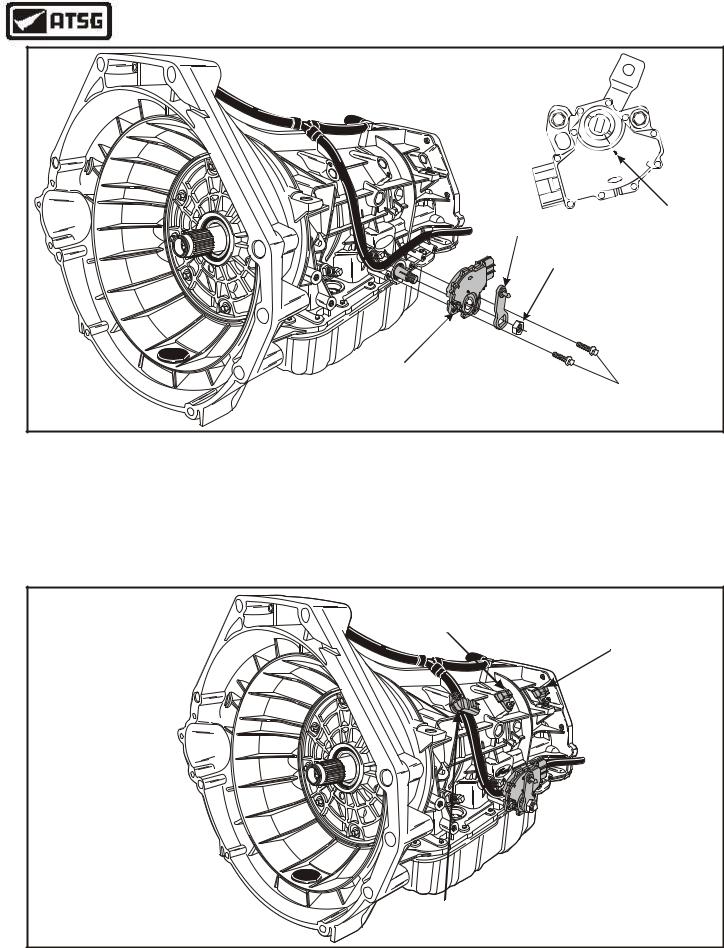
EXTERNAL COMPONENTS
1.Place the manual lever in the neutral position and install the Digital Transmission Range sensor, as shown in Figure 182.
2.Install the two DTR retaining bolts finger tight at this time (See Figure 182).
3.Install the adjustment gage and tighten the two DTR bolts by alternating from side to side, and torque to 10 Nm (89 in.lb.).
Continued on Page 103
Intermediate Shaft
Speed Sensor Output Shaft
Speed Sensor
AA-392F7-P2L1 |
|
L |
1600 |
TRA |
NEU |
Turbine Shaft
Speed Sensor
Copyright © 2004 ATSG
Figure 183
102 |
AUTOMATIC TRANSMISSION SERVICE GROUP |
|
Technical Service Information
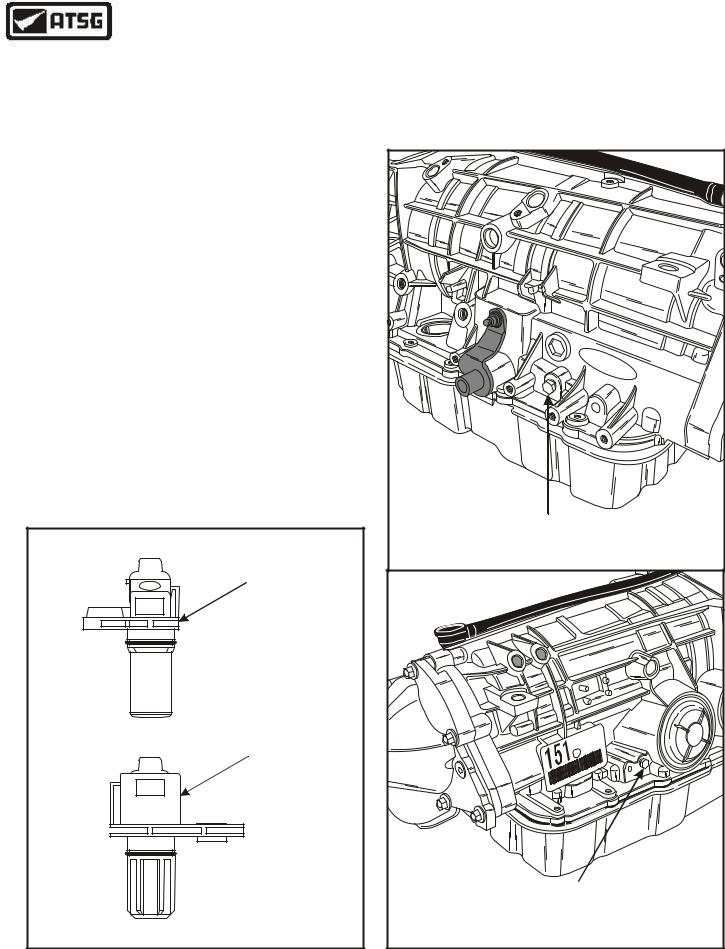
EXTERNAL COMPONENTS (Cont'd)
4.Install the outer manual control lever and nut, torque nut to 48 N•m ( 35 ft.lb.).
5.Install a new "O" ring on turbine speed sensor and install into case in the location, as shown in Figure 183.
Note: Use Figure 184 to identify the three speed sensor assemblies, and use the chart on Page 17 for proper Ohms readings.
6.Install a new "O" ring on the intermediate shaft speed sensor and install into case in the location shown in Figure 183.
Note: Use Figure 184 to identify the three speed sensor assemblies, and use the chart on Page 17 for proper Ohms readings.
7.Install a new "O" ring on output shaft speed sensor and install in case in the location shown in Figure 183.
Note: Use Figure 184 to identify the three speed sensor assemblies, and use the chart on Page 17 for proper Ohms readings.
8.Torque all three speed sensor retaining bolts
to 10 Nm (89 in.lb.).
Turbine And Output
Shaft Speed Sensor
Ford
XW4P-7H 103 AA
Intermediate Shaft
Speed Sensor
XW4P-7M 103 AA
Figure 184
9.Check and ensure that both oil pressure plugs are tight, as shown in Figure 185.
Continued on Page 104
|
|
|
|
F |
|
|
|
|
|
|
ord |
Line Pressure Tap |
|||||
(Pressure Control Solenoids "A" And "B") |
|||||
|
|
|
|
|
C |
|
|
|
|
-A |
|
|
|
|
|
4P |
|
|
|
|
|
XW |
|
|
|
|
|
-B |
|
|
|
|
|
JL |
61 |
|
|
|
|
R |
|
|
|
|
|
43 |
|
|
|
|
|
00 |
17 |
|
|
|
|
|
C |
|
|
|
|
-9 |
|
|
|
|
|
BD |
|
|
|
00 |
43 |
61 |
|
R J |
L- |
B |
|
|
|
|
|
|
|
|
|
Pressure Control Solenoid "C" |
|||||
Pressure Tap |
|
||||
|
|
|
|
Copyright © 2004 ATSG |
|
Figure 185
AUTOMATIC TRANSMISSION SERVICE GROUP |
103 |
|
Technical Service Information
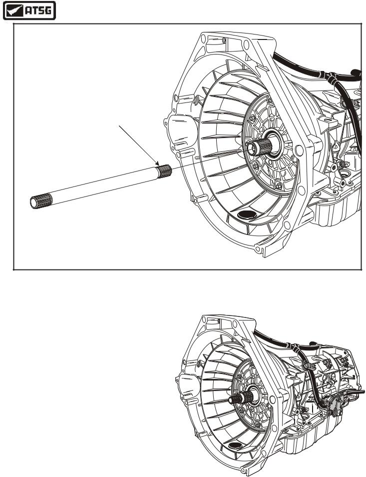
Short Spline End |
Into Transmission |
Copyright © 2004 ATSG |
Figure 186
EXTERNAL COMPONENTS
9.Install the input shaft into the transmission, as shown in Figure 186.
Caution: The splines on input shaft are not the same length on both ends. The end with the shorter splines goes into transmission, as shown in Figure 186.
10.Remove form bench fixture and remove the universal transmission fixture.
CONGRATULATIONS!
YOU ARE FINISHED.
SPECIAL NOTE:
THIS UNIT REQUIRES MERCON® V.
AA-392F7-P2L1 |
|
L |
1600 |
TRA |
NEU |
104 |
AUTOMATIC TRANSMISSION SERVICE GROUP |
|
Technical Service Information
|
|
|
|
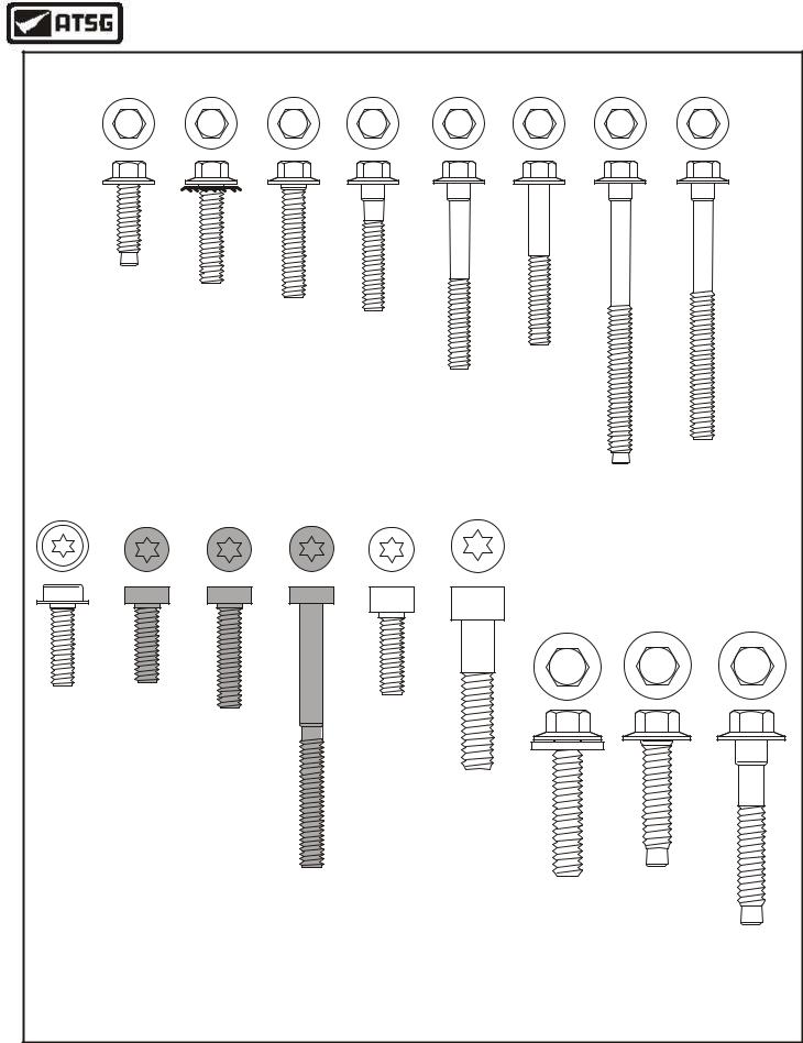
BOLT CHART |
|
|
|
|
|
|
8 mm |
8 mm |
8 mm |
8 mm |
8 mm |
8 mm |
8 mm |
|
8 mm |
|
Pan |
DTR |
Valve |
Detent |
|
|
|
|
|
|
Bolts |
Sensor |
|
|
|
|
|
||
|
Body |
|
|
|
|
|
|||
|
(16) |
(2) |
Spring |
|
|
|
|
|
|
|
(1) |
|
|
|
|
|
|||
|
(19mm) |
(25mm) |
(1) |
|
|
|
|
|
|
|
(27mm) |
|
|
|
|
|
|||
|
|
|
(30mm) |
Valve |
|
|
|
|
|
|
|
|
|
|
|
|
|
||
|
|
|
|
|
|
|
|
|
|
|
|
|
|
|
Body |
Valve |
|
|
|
|
|
|
|
|
(1) |
|
|
|
|
|
|
|
|
|
Body |
|
|
|
|
|
|
|
|
|
(45mm) |
|
|
|
|
|
|
|
|
|
(18) |
|
|
Filter |
|
|
|
|
|
|
|
(40mm) |
|
|
|
|
|
|
|
|
|
|
|
(2) |
|
|
|
|
|
|
|
Rev Servo |
|
||
|
|
|
|
|
|
(60mm) |
|||
30 Torx |
30 Torx |
30 Torx |
30 Torx |
30 Torx |
40 Torx |
|
(4) |
||
|
|
|
|||||||
|
|
|
|
|
|
(68mm) |
|
|
|
|
|
|
|
|
|
10 mm |
10 mm |
10 mm |
|
Speed |
Spacer |
|
|
Center |
|
|
|
|
|
Sensors |
Plate |
Solenoid |
|
|
|
|
|
|
|
|
Support |
|
|
|
|
|
|||
(3) |
(3) |
Body |
|
(1) |
|
|
|
|
|
(19mm) |
(20mm) |
(1) |
|
(20mm) |
|
|
|
|
|
|
|
(25mm) |
|
|
Stator To |
|
|
|
|
|
|
|
|
|
Pump Body |
|
|
|
|
|
|
|
|
|
(6) |
|
|
|
|
|
|
|
|
|
(35mm) |
|
|
|
|
|
|
|
Solenoid |
|
|
Pump to |
4WD Adapter |
||
|
|
|
Body |
|
|
Housing |
|||
|
|
|
(7 Req.) |
|
|
Case |
(7) |
|
|
|
|
|
(63mm) |
|
|
(8) |
(29mm) |
2WD Extn |
|
|
|
|
|
|
|
(32mm) |
|
|
Housing |
|
|
|
|
|
|
|
|
|
(7) |
|
|
|
|
|
|
|
|
|
(44mm) |
|
|
|
|
|
|
|
Copyright © 2004 ATSG |
||
Figure 187
AUTOMATIC TRANSMISSION SERVICE GROUP |
105 |
|
Technical Service Information
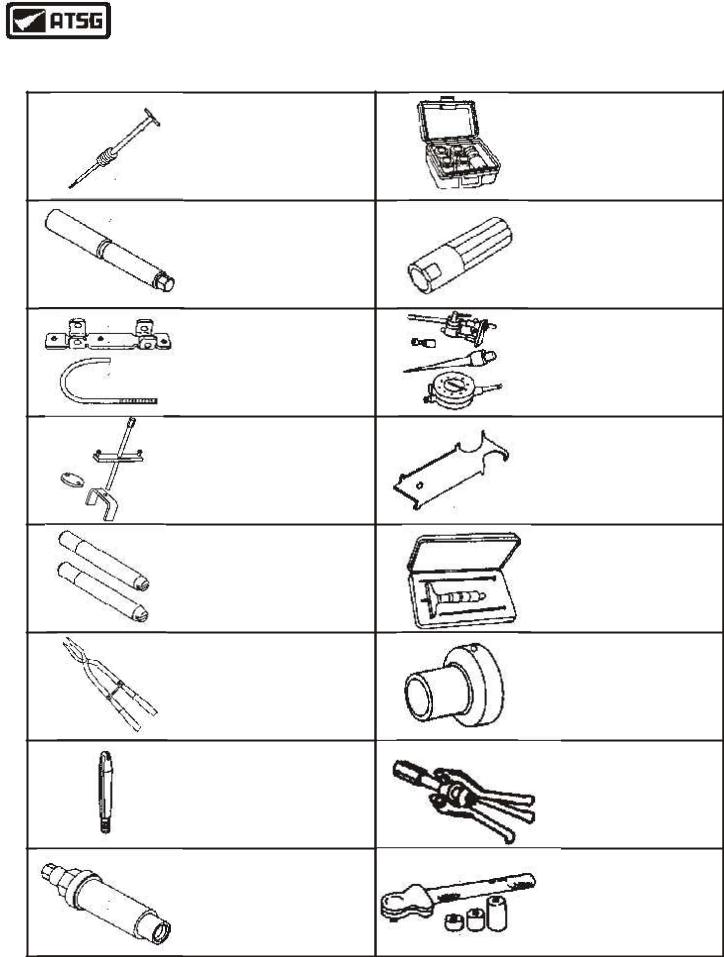
SPECIAL SERVICE TOOLS
FORD OR "ROTUNDA" PART NUMBERS ARE REFERENCED
IMPACT SLIDE HAMMER |
OIL PUMP ALIGNMENT TOOL |
100-001 (T50T-100-A) |
307-S039 (T74P-77103-X) |
OUTPUT SHAFT FLANGE INSTALLER |
PUMP GEAR "O" RING SIZER |
307-404 |
307-338 (T95L-700-10-G) |
SERVO COVER COMPRESSOR |
DIAL INDICATOR |
307-402 |
100-002 (TOOL-4201-C) |
INT CUSHION SPRING COMPRESSOR |
TRS ALIGNMENT TOOL |
307-401 |
307-351 (T97L-70010-A) |
DEPTH MICROMETER
OIL PUMP ALIGNMENT DOWELS
303-D206 (D8OP-4201-A)
307-399
RETAINING RING PLIERS |
OUTPUT SHAFT BEARING INSTALLER |
307-343 (T95P-77001-AHR) |
307-348 (T97T-77110-A) |
VALVE BODY GUIDE PIN (.248")
BEARING REMOVER
307-334 (T95L-70010-C)
308-047 (T77F-1102-A)
(2 REQUIRED)
OUTPUT FLANGE INSTALLER |
BAND ADJUSTMENT TOOL |
205-479 |
307-S022 (T71P-77370-A) |
Copyright © 2004 ATSG
Figure 188
106 |
AUTOMATIC TRANSMISSION SERVICE GROUP |
|
Technical Service Information
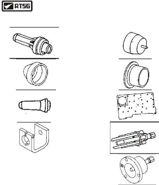
SPECIAL SERVICE TOOLS
FORD OR "ROTUNDA" PART NUMBERS ARE REFERENCED
EXTENSION HOUSING SEAL INSTALLER |
FORWARD CLUTCH |
|
307-038 (T74P-77052-A) |
INNER LIP SEAL PROTECTOR |
|
|
307-051 (T74P-77548-A) |
|
|
|
|
COAST AND DIRECT CLUTCH |
FORWARD CLUTCH |
|
INNER LIP SEAL PROTECTOR |
||
OUTER LIP SEAL PROTECTOR |
||
307-049 (T74P-77404-A) |
||
307-052 (T74P-77548-B) |
||
|
||
|
|
|
FRONT PUMP |
AIR TEST PLATE |
|
SEAL INSTALLER |
307-405 |
|
307-349 (T97T-77000-A) |
|
|
|
|
|
FRONT PUMP |
UNIVERSAL PULLER |
|
REMOVAL TOOL |
307-001 (TOOL-1175-AC) |
|
307-397 |
|
|
|
|
|
A very acceptable alternative for this tool is |
OUTPUT FLANGE |
|
REMOVAL TOOL |
||
available from Trans-Tool in San Antonio and is |
||
307-408 |
||
universal so it works on many other models. Their |
|
|
part number is T-0033. |
|
|
|
|
|
|
|
|
|
|
|
|
Copyright © 2004 ATSG |
|
|
|
Figure 189
AUTOMATIC TRANSMISSION SERVICE GROUP |
107 |
|

Technical Service Information
TORQUE SPECIFICATIONS
Description |
Nm |
In.Lb. |
Ft.Lb. |
Pump Stator To Pump Cover ................................................................... |
25 |
|
18 |
Spacer Plate Retaining Bolts ................................................................... |
10 |
89 |
|
Inside Detent Lever Nut ........................................................................... |
48 |
|
35 |
Oil Pump To Case Bolts ........................................................................... |
25 |
|
18 |
Center Support Bolt ................................................................................ |
11 |
100 |
|
Valve Body Bolts ..................................................................................... |
10 |
89 |
|
Valve Body Cover Bolts ........................................................................... |
10 |
89 |
|
Solenoid Body Bolts ............................................................................... |
8 |
71 |
|
Reverse Servo Bolts ................................................................................ |
10 |
89 |
|
Filter Bolts .............................................................................................. |
10 |
89 |
|
Bottom Pan Bolts .................................................................................... |
11 |
100 |
|
Extension Housing Bolts ......................................................................... |
39 |
|
29 |
Output Flange Retaining Nut .................................................................. |
131 |
|
97 |
Transmission Range Sensor .................................................................... |
10 |
89 |
|
Outer Manual Shift Lever Nut ................................................................. |
48 |
|
35 |
Speed Sensors ......................................................................................... |
10 |
89 |
|
Figure 190
FORD 5R55N VERSUS 5R55W
TRANSMISSION DIFFERENCES
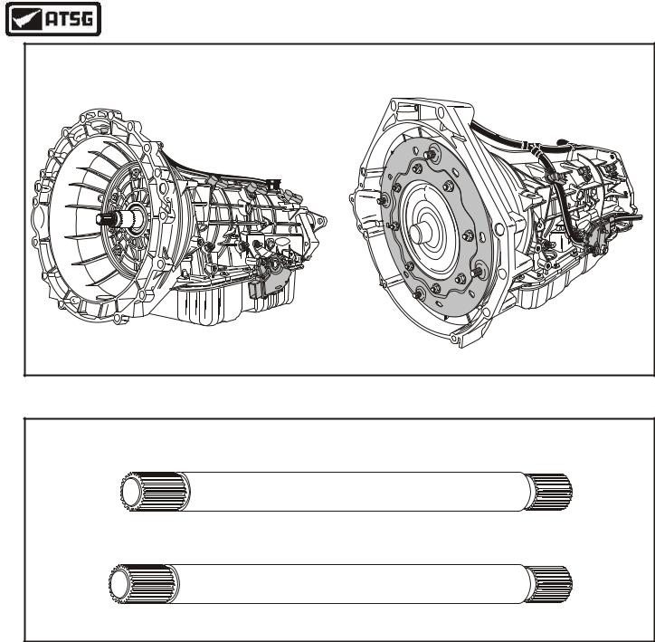
The Ford Motor Companys 5R55N (Non Sync.) transmission first appeared in the 2000 Lincoln "LS" and some of the Jaguar Models, which we are already somewhat familiar with. Beginning at the start of production for model year 2002, Ford has introduced the 5R55W (Wide Ratio) transmission into the some 4WD models of the Ranger and Explorer, and the 5R55S (Sync) transmission into some of the 2WD Ranger/Explorer and the 2004 Thunderbird. The internal parts look almost identical, but will not interchange with their look alikes in the 5R55N transmission. The information in this bulletin will help you in getting the proper replacement parts back into the proper unit. Externally these transmissions are easy to identify and we have provided illustrations of both transmissions in Figure 191.
Figure 192 is an illustration of the two different turbine shafts. They are identical in every respect except for the overall length.
Figures 193 and 194 show you the differences in the overdrive sun gear and drive plate. Notice the differences in the tooth count on the sun gear.
Figures 195 and 196 are illustrations of the two different coast clutch housings. Notice that the slots to accept the tabs on the adapter plate are narrower and angled to the left at a very slight angle. This means that it will engage into the coast clutch housing in only one direction.
Continued on next Page 109 |
Copyright © 2004 ATSG |
108 |
AUTOMATIC TRANSMISSION SERVICE GROUP |
|

Technical Service Information
Figure 197 illustrates the internal components of the forward clutch housing for the 5R55N. Figure 198 illustrates the internal components of the forward clutch housing for the 5R55W/S. The only difference in the empty forward clutch housings is the champfer in the 5R55W/S is wider.
Figure 199 is illustrations of the two different, completed forward clutch housing assemblies. Notice that the only visible difference is the piston and the return spring retainer.
Figure 200 and 201 are illustrations of the two different forward planetary carriers and the two different forward planetary internal ring gears. Notice the different tooth count on the planetary carrier pinions and the different tooth counts on the forward internal ring gear.
Figure 202 and 203 are illustrations of the two different sun gear and shell assemblies. Notice that the 5R55N uses an intermediate sprag and the 5R55W/S does not. This required a taller spacer as shown in Figure 203. Notice also the difference in tooth count of the forward sun gear, but the rear sun gear remains the same.
Figure 204 shows 3 dimensional illustrations of the two different valve body assemblies. The most noticeable difference is the 5R55W/S does not use a cover plate. The bolt pattern however, is exactly the same as the 5R55N transmission.
Figure 205 shows illustrations of the two different valve body assemblies in the worm track area, different amount of checkballs and the locations, and the retainer locations for both valve bodies.
Figure 206 is illustrations of the two different valve body spacer plates. One hole location for the spacer plate retaining bolts has changed to help prevent you from a mis-match.
Figure 207 and 208 are illustrations of the two different reverse servo housings. Notice that the 5R55W/S transmission has two feed holes in the housing, has a larger diameter for the inner piston seal, and has a different reverse servo check valve.
Figure 209 is illustrations of the two different reverse servo return springs. Notice the difference in the spring dimensions.
Figure 210 is illustrations of the two different of the two different reverse servo pistons. Notice the difference in the outside diameter of the body, to accommodate the larger diameter in the housing.
Figures 211 and 212 are illustrations of the two different intermediate servo covers and the intermediate servo pistons.
CAUTION:
NONE OF THE COMPONENTS LISTED ABOVE WILL
INTERCHANGE BETWEEN THESE TWO SIMILAR TRANSMISSIONS
AUTOMATIC TRANSMISSION SERVICE GROUP |
109 |
|
Technical Service Information
5R55N |
5R55W/S |
|
|
|
(4WD Version Shown) |
|
|
|
F |
ord |
|
|
|
Ford |
|
|
|
|
AA-392721PFL- |
Ford |
|
|
L |
|
1600 |
TRA |
|
|
NEU |
||
|
|
||
F |
|
|
|
dro |
|
|
|
|
Copyright © 2004 ATSG |
||
Figure 191
TURBINE SHAFT DIFFERENCES
"5R55N" Turbine Shaft
"5R55W/S" Turbine Shaft .200" Longer
Copyright © 2004 ATSG
Figure 192
110 |
AUTOMATIC TRANSMISSION SERVICE GROUP |
|