

5R55W
.pdfTechnical Service Information
A VERY HEARTY "THANK YOU" TO LEON AUTRY OF
A & REDS TRANSMISSION PARTS
FOR SUPPLYING US WITH THE TRANSMISSION THAT MADE
A & REDS TRANSMISSION PARTS
PLEASE FEEL FREE TO CALL TODAY
1 800 835-1007
WE HAVE WHAT YOU NEED FOR "ALL" YOUR TRANSMISSION NEEDS!
Ford
Ford
A & REDS
TRANSMISSION
PARTS
 WICHITA, KANSAS
APR KAN |
SAS 2001 |
IM-EASY |
|
Copyright © 2004 ATSG
AUTOMATIC TRANSMISSION SERVICE GROUP |
71 |
|
Technical Service Information
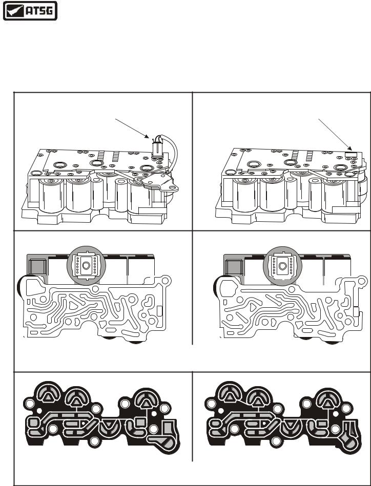
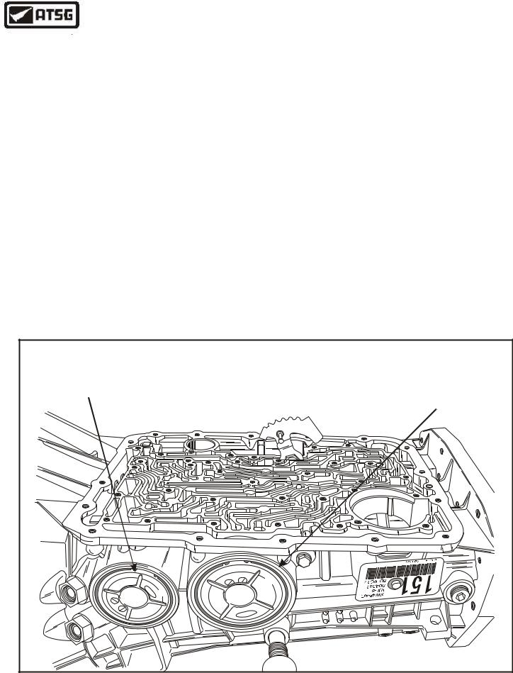
SOLENOID BODY ASSEMBLY "DIFFERNCES"
The solenoid bodies are different between the 5R55W/S and the 5R55N transmissions, and they
"Will Not" interchange. The solenoid body differences and how to identify between the two, are shown in Figure 119 below.
Extra care here when selecting replacement parts, including the solenoid body gasket, will eliminate some of the troublesome problems that may be encountered after installation.
Continued in Page 73
"5R55N" SOLENOID BODY |
|
"5R55W/S" SOLENOID BODY |
||
"USES" REVERSE PRESSURE |
"DOES NOT" USE REVERSE |
|||
|
SWITCH |
|
PRESSURE SWITCH |
|
11 |
1 |
|
11 |
1 |
16 |
6 |
|
16 |
6 |
|
"5R55N" |
"NOTICE" DIFFERENCE IN |
"5R55W/S" |
|
|
|
WORM TRACKS |
|
|
|
|
"NOTICE" DIFFERENCE IN |
|
|
|
"5R55N" |
GASKETS |
"5R55W/S" |
|
Figure 119
72 |
AUTOMATIC TRANSMISSION SERVICE GROUP |
|

Technical Service Information
SOLENOID BODY ASSEMBLY
1.The solenoid body is serviced as a complete assembly only, from Ford Motor Company, however the aftermarket gasket sets do come with a new gasket and "O" rings.
2.Remove the worm track plate by prying back the locking tabs (See Figure 121).
3.Remove and discard the solenoid body to worm track plate gasket (See Figure 121).
4.Remove and discard the two solenoid body to case "O" rings, as shown in Figure 121.
5.Ensure that you have the proper gasket for the 5R55W/S, as shown in Figure 120. Refer to Figure 119 for the differences.
6.Install the new solenoid body to worm track plate gasket over the dowels on the solenoid body, as shown in Figure 121.
7.Install the worm track plate over the dowels on the solenoid body, as shown in Figure 121, and snap into position.
8.Install two new solenoid body to case "O" ring seals, as shown in Figure 121.
9.Set the completed solenoid body aside for the final assembly process (See Figure 122).
|
SOLENOID BODY ASSEMBLY |
|
|
|
1 |
|
|
12394 |
|
2 |
3 |
|
4 |
|
1. |
SOLENOID BODY WORM TRACK PLATE |
|
2. |
SOLENOID BODY TO WORM TRACK PLATE GASKET |
|
3. |
SOLENOID BODY TO CASE "O" RINGS (2 REQUIRED) |
|
4. |
SOLENOID BODY ASSEMBLY |
|
|
Copyright © 2004 ATSG |
|
Figure 121
5R55W/S SOLENOID BODY GASKET |
Copyright © 2004 ATSG |
Figure 120
COMPLETED SOLENOID BODY ASSEMBLY |
12394 |
Copyright © 2004 ATSG |
Figure 122
AUTOMATIC TRANSMISSION SERVICE GROUP |
73 |
|
Technical Service Information
|
|
EXTENSION |
|
|
HOUSING SEAL |
EXTENSION |
|
|
HOUSING |
|
|
BUSHING |
|
|
|
|
EXTENSION |
|
|
HOUSING |
|
|
2WD MODELS |
|
1 |
|
|
L |
|
® |
2 |
|
P |
rdoF |
|
- |
||
|
7 |
|
|
A |
|
|
0 |
|
|
3 |
|
|
8 |
|
|
- |
|
|
A |
|
|
B |
|
|
|
Copyright © 2004 ATSG |
Figure 123
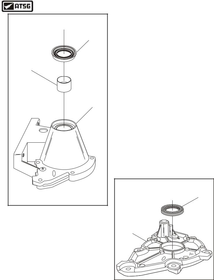
EXTENSION/4WD ADAPTER HOUSING
1.Inspect the 2WD extension housing bushing for any wear and/or damage.
2.Replace the 2WD extension housing bushing as necessary, using the appropriate puller and bushing driver. Use Figure 123 as a guide.
3.Install a new extension housing yoke seal, as shown in Figure 123, using the appropriate seal driver.
4.If you have a 4WD, install new adapter housing seal, as shown in Figure 124, using the proper seal driver.
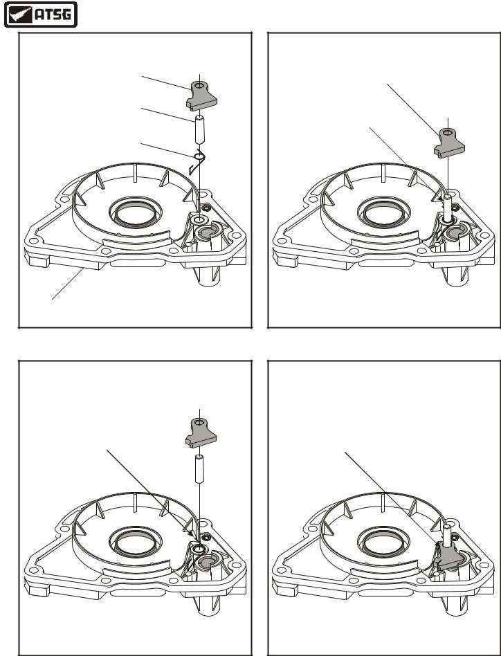
5.Turn the 2WD extension housing or the 4WD adapter housing over to install the park pawl components, as shown in Figure 125, as the procedure is the same for either model.
6.Install the parking pawl return spring onto the adapter housing, with the leg of the return spring in front of housing shoulder, as shown in Figure 126.
7.Install the parking pawl pivot pin through the center of return spring, as shown in Figure 127.
8.Install the parking pawl over the pivot pin and hook the return spring on the parking pawl, as shown in Figure 128.
9.Set the completed extension housing aside for the final assembly process.
|
|
|
|
|
|
|
|
|
|
|
|
|
|
|
4WD ADAPTER |
|
|
|
|
|
|
|
|
|
|
|
|
|
|
|
HOUSING SEAL |
4WD ADAPTER |
|
|
|
|
|
|
|
|
|
|
|
|
|
|
|
HOUSING |
|
|
|
|
|
|
|
|
|
|
|
|
|
|
|
|
|
|
|
|
|
|
|
|
P |
2 |
L |
1 |
|
|
F |
|
|
|
|
|
|
|
7 |
- |
|
|
o |
||||
|
|
|
|
|
|
A |
|
|
r |
||||||
|
|
|
|
|
0 |
|
|
d |
|||||||
|
|
|
|
3 |
|
|
|
|
|
||||||
|
|
|
9 |
|
|
|
|
|
|
||||||
|
|
- |
|
|
|
|
|
|
|
|
|||||
|
B |
|
|
|
|
|
|
|
|
|
|
||||
A |
|
|
|
|
|
|
|
|
|
|
|
||||
|
|
|
|
|
|
|
|
|
|
|
|
|
|||
|
|
|
|
|
|
|
|
|
|
|
|
|
|
||
|
|
|
|
|
|
|
|
|
|
|
|
|
|
|
|
|
|
|
|
|
|
|
|
|
|
|
|
|
|
|
Copyright © 2004 ATSG |
Figure 124
74 |
AUTOMATIC TRANSMISSION SERVICE GROUP |
|
Technical Service Information
|
PARKING PAWL |
|
PARKING PAWL |
|
PIVOT PIN |
|
PARKING PAWL |
|
RETURN SPRING |
|
6 |
4WD ADAPTER |
|
HOUSING |
Copyright © 2004 ATSG |
PARKING PAWL |
INSTALL PARKING PAWL |
PIVOT PIN AS SHOWN |
THROUGH CENTER |
OF SPRING |
6 |
Copyright © 2004 ATSG |
Figure 125 |
Figure 127 |
INSTALL PARKING PAWL |
RETURN SPRING AS SHOWN |
WITH SPRING LEG IN FRONT |
OF HOUSING SHOULDER |
6 |
Copyright © 2004 ATSG |
COMPLETED EXTENSION HOUSING |
INSTALL PARKING PAWL |
RETURN SPRING AS SHOWN |
WITH SRING HOOKED ON |
PARKING PAWL |
6 |
Copyright © 2004 ATSG |
Figure 126 |
Figure 128 |
AUTOMATIC TRANSMISSION SERVICE GROUP |
75 |
|
Technical Service Information
TRANSMISSION CASE ASSEMBLY
1.Inspect the transmission case thoroughly for wear, damaged surfaces, or stripped threads.
2.Inspect the rear case caged needle bearing and replace as necessary using the appropriate tools to remove and install (See Figure 131).
Note: If replacement is necessary ensure that the sealing ring end of the bearing faces rear, as shown in Figure 131.
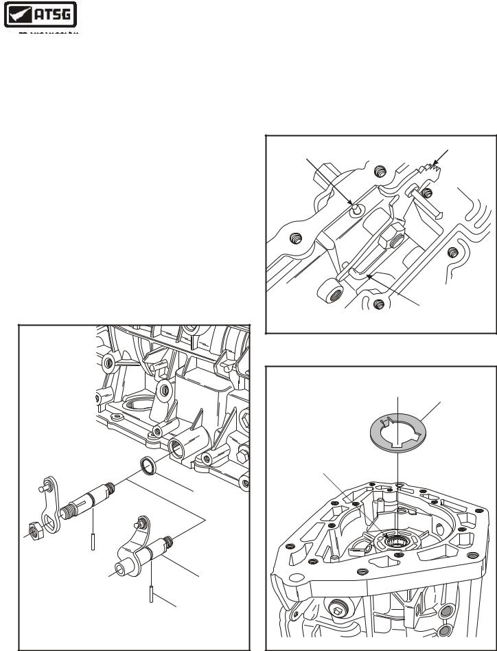
3.Install new manual lever seal into case using the appropriate seal driver (See Figure 129).
4.There are two different styles of manual lever design, as shown in Figure 129.
5.Install the manual lever, inside detent lever and park rod assembly, manual lever retaining pin and torque nut to 48Nm (35 ft.lb.). Refer to Figure 130.
Note: Do Not allow the wrench to strike the manual valve inner detent lever pin.
MANUAL |
LINKAGE |
SEAL |
MANUAL |
LINKAGE |
MANUAL LINKAGE |
RETAINING PIN |
Copyright © 2004 ATSG |
6.Install the number 11 thrust washer into rear of case, as shown in Figure 131, and retain with a small amount of Trans-Jel®.
Continued on Page 78
MANUAL LEVER |
INSIDE DETENT |
RETAINING PIN |
LEVER |
|
PARK ROD |
|
Copyright © 2004 ATSG |
Figure 130
NUMBER ELEVEN |
THRUST WASHER |
If Bearing Replacement |
Is Necessary, Ensure |
Sealing Ring Faces Rear |
Copyright © 2004 ATSG |
Figure 129 |
Figure 131 |
76 |
AUTOMATIC TRANSMISSION SERVICE GROUP |
|

Technical Service Information
OVERDRIVE SERVO COMPONENTS |
INTERMEDIATE SERVO COMPONENTS |
INTERMEDIATE SERVO
RETURN SPRING
OVERDRIVE SERVO
RETURN SPRING
INTERMEDIATE SERVO
PISTON ASSEMBLY
OVERDRIVE SERVO
PISTON ASSEMBLY
INTERMEDIATE SERVO
COVER "O" RING SEAL
OVERDRIVE SERVO
COVER "O" RING SEALS
INTERMEDIATE SERVO
COVER
OVERDRIVE SERVO
COVER
INTERMEDIATE SERVO
COVER SNAP RING
OVERDRIVE SERVO
COVER SNAP RING
|
Copyright © 2004 ATSG |
|
|
Copyright © 2004 ATSG |
|
|
|
||
|
|
|
||
|
|
|||
|
Figure 132 |
|
|
Figure 133 |
AUTOMATIC TRANSMISSION SERVICE GROUP |
77 |
|
Technical Service Information
TRANSMISSION CASE ASSEMBLY (Cont'd)
7.Install the transmission case into the fixture and rotate so that pan surface is facing up, as shown in Figure 134.
8.Install new "O" ring seals into the overdrive servo cover grooves, as shown in Figure 132, and lubricate with small amount of Trans-Jel®.
9.Inspect the molded lip seal on the overdrive servo piston for any wear and/or damage and replace piston assembly as necessary.
10.Lubricate molded seal and the overdrive servo case bore with a small amount of Trans-Jel®, and install return spring on back side, as shown in Figure 132.
11.Install the overdrive servo cover assembly into the case bore, compress the return spring and install the snap ring (See Figure 134).
12.Install new "O" ring seals into the intermediate servo cover grooves, as shown in Figure 133, and lubricate with small amount of Trans-Jel®.
13.Inspect the molded lip seals on the intermediate servo piston for any wear and/or damage and replace piston assembly as necessary.
14.Lubricate molded seals and both intermediate servo cover bores with a small amount of Trans-Jel®.
15.Install the intermediate servo piston into the cover with a twisting motion, until it is fully seated (See Figure 133).
16.Install the servo return spring over the pin on the back side as shown in Figure 133.
17.Install the intermediate servo assembly into the case bore, compress the return spring and install the snap ring (See Figure 134).
18.With these two servo assemblies installed, you are now ready for the final assembly process.
|
|
SERVOS INSTALLED IN TRANSMISSION CASE |
|||
OVERDRIVE SERVO |
|
|
|
|
INTERMEDIATE SERVO |
|
|
|
|
|
|
|
|
|
|
|
62 |
|
|
|
|
|
- |
|
|
|
|
|
1 |
8 |
|
|
|
|
|
A |
|
|
|
|
|
G |
F |
|
|
|
CA |
|
o |
|
|
||
|
|
rd |
|
|
0 |
|
|
R |
65 |
|
|
|
|
3 |
|
|
|
|
|
T9 |
3 |
|
|
|
|
8 |
|
|
|
|
0 |
A |
|
|
|
|
4 |
A |
|
|
|
5 |
|
|
|
||
6 |
9 |
|
|
F |
|
|
1 |
|
|
|
|
3 |
|
|
o |
||
R |
|
|
dr |
|
|
|
|
|
|
|
Copyright © 2004 ATSG |
Figure 134
78 |
AUTOMATIC TRANSMISSION SERVICE GROUP |
|
Technical Service Information
OUTPUT SHAFT |
(4WD VERSION SHOWN) |
PARK GEAR |
NUMBER ELEVEN |
THRUST WASHER |
Copyright © 2004 ATSG |
FINAL TRANSMISSION ASSEMBLY
INTERNAL COMPONENTS
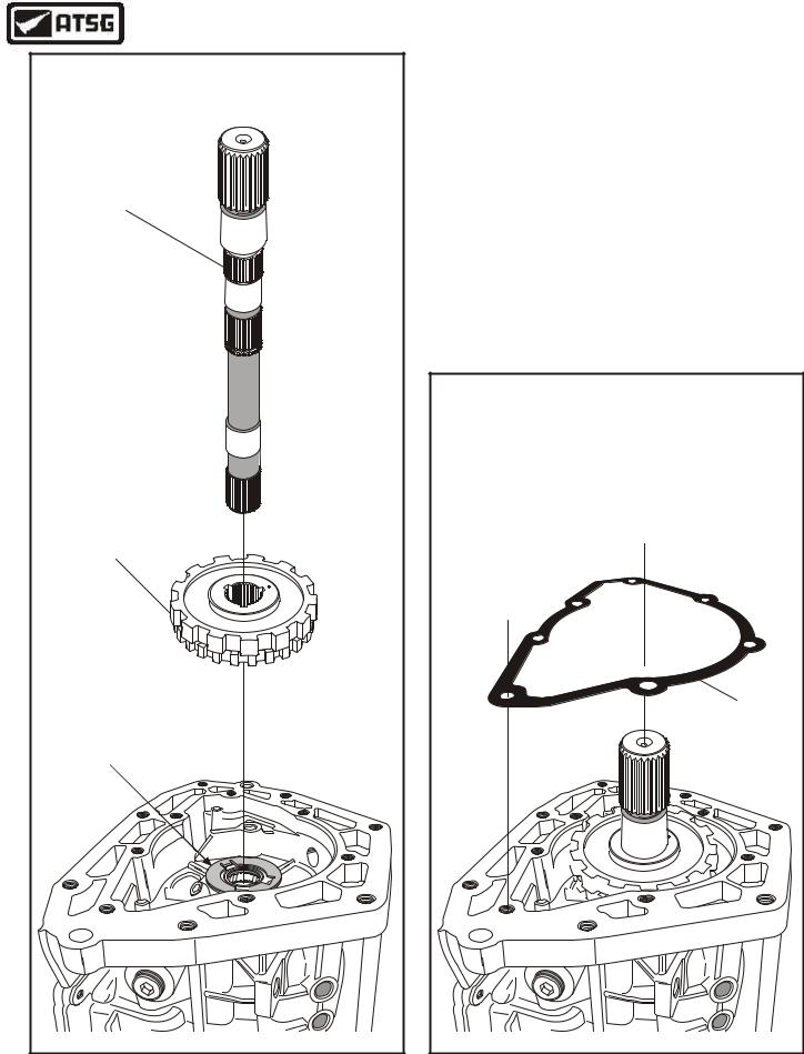
1.Rotate transmission in fixture so that rear of the case is facing up, as shown in Figure 135.
2.Ensure that the number 11 thrust washer is still in place, as shown in Figure 135.
3.Install the park gear and output shaft, as shown in Figure 135.
4.Install the extension housing gasket, as shown in Figure 136, and retain with a small amount of Trans-Jel®.
Continued on Page 80
EXTENSION |
GASKET |
Copyright © 2004 ATSG |
Figure 135 |
Figure 136 |
AUTOMATIC TRANSMISSION SERVICE GROUP |
79 |
|
Technical Service Information
INTERNAL COMPONENTS (Cont'd)
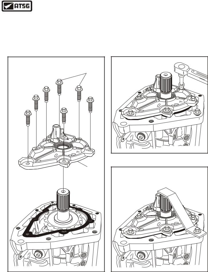
5.Install the preassembled 4WD adapter housing ensuring that the parking pawl is engaged on the park rod properly (See Figure 137).
6.Install the seven 4WD adapter housing bolts and torque bolts to 39 N•m (29 ft.lb.), as shown in Figure 138.
|
|
|
|
|
|
|
|
|
|
|
|
|
|
RETAINING BOLTS |
|
|
|
|
|
|
|
|
|
|
|
|
|
|
(7 REQUIRED) |
|
|
|
|
|
|
|
|
P |
2 |
L |
1 |
|
|
F |
|
|
|
|
|
|
7 |
- |
|
|
o |
||||
|
|
|
|
|
A |
|
|
r |
||||||
|
|
|
|
0 |
|
|
d |
|||||||
|
|
|
|
|
|
|
||||||||
|
|
- 9 |
3 |
|
|
|
|
|
|
|||||
|
|
|
|
|
|
|
|
|
|
|||||
|
B |
|
|
|
|
|
|
|
|
|
|
|||
A |
|
|
|
|
|
|
|
|
|
|
|
|||
|
|
|
|
|
|
|
|
|
|
|
|
|||
|
|
|
|
|
|
|
|
|
|
|
|
|
||
|
|
|
|
|
|
|
|
|
|
|
|
|
|
|
|
|
|
|
|
|
|
|
|
|
|
|
|
|
4WD ADAPTER |
|
|
|
|
|
|
|
|
|
|
|
|
|
|
HOUSING |
|
|
|
|
|
|
|
|
|
|
|
|
|
|
Copyright © 2004 ATSG |
Figure 137
7.Install the temporary holding strap, as shown in Figure 139, to retain the output shaft in the transmission intill snap ring is installed.
Continued on Page 81
|
|
|
|
|
|
|
|
P |
2 |
L |
1 |
|
|
F |
|
|
|
|
|
A |
7 |
- |
|
|
r |
o |
|||
|
|
|
|
0 |
|
|
d |
|||||||
|
|
- 9 |
3 |
|
|
|
|
|
|
|||||
|
|
|
|
|
|
|
|
|
|
|||||
|
B |
|
|
|
|
|
|
|
|
|
|
|||
A |
|
|
|
|
|
|
|
|
|
|
|
|||
|
|
|
|
|
|
|
|
|
|
|
|
|||
|
|
|
|
|
|
|
|
|
|
|
|
|
||
|
|
|
|
|
|
|
|
|
|
|
|
|
|
|
|
|
|
|
|
|
|
|
|
|
|
|
|
|
Copyright © 2004 ATSG |
Figure 138
CAUTION: INSTALL TEMPORARY |
||||||||||||||
HOLDING STRAP AS SHOWN TO |
||||||||||||||
RETAIN OUTPUT SHAFT. |
||||||||||||||
|
|
|
|
|
|
|
|
P |
2 |
L |
1 |
|
|
F |
|
|
|
|
|
|
7 |
- |
|
|
o |
||||
|
|
|
|
|
A |
|
|
r |
||||||
|
|
|
|
0 |
|
|
d |
|||||||
|
|
|
3 |
|
|
|
|
|
||||||
|
|
- 9 |
|
|
|
|
|
|
||||||
|
B |
|
|
|
|
|
|
|
|
|
|
|||
A |
|
|
|
|
|
|
|
|
|
|
|
|||
|
|
|
|
|
|
|
|
|
|
|
|
|||
|
|
|
|
|
|
|
|
|
|
|
|
|
||
|
|
|
|
|
|
|
|
|
|
|
|
|
|
|
|
|
|
|
|
|
|
|
|
|
|
|
|
|
Copyright © 2004 ATSG |
Figure 139
80 |
AUTOMATIC TRANSMISSION SERVICE GROUP |
|