

5R55W
.pdfTechnical Service Information
DIGITAL TRANSMISSION RANGEScanner(DTR)Data SENSOR DIAGNOSISScanner Data
SELECTOR POSITION |
PID:TR |
|
PID:TR_D |
|
PID:TR_V |
||
TR4 |
TR3A |
TR2 |
|
TR1 |
TR3A (175B pin 9 to sigrtn) |
||
|
|
|
|||||
PARK |
P/N |
0 |
0 |
0 |
|
0 |
0.0 Volts |
REVERSE |
REV |
1 |
1 |
0 |
|
0 |
1.3 to 1.8 Volts |
NEUTRAL |
NTRL |
0 |
1 |
1 |
|
0 |
1.3 to 1.8 Volts |
OVERDRIVE |
OD* |
1 |
1 |
1 |
|
1 |
1.3 to 1.8 Volts |
MANUAL 3 |
MAN 3 |
1 |
0 |
1 |
|
0 |
0.0 Volts |
MANUAL 2 |
MAN 2 |
1 |
0 |
0 |
|
1 |
0.0 Volts |
MANUAL 1 |
MAN 1 |
0 |
0 |
1 |
|
1 |
0.0 Volts |
* Will read "Drive" if OD is canceled.
1.TR_V is the voltage at PCM connector 175B, pin 9 (TR3ACircuit) to Signal Return.
2."In-Between" reading may be caused by shift cable or DTR sensor misalignment or a DTR circuit failure of TR1, TR2, TR3A, TR4.
3.TR_D: 1 = Open DTR Switch
0 = Closed DTR Switch
4.Breakout Box readings are taken from PCM signal pins for TR1, TR2, TR3A, TR4 to Signal Return.
Voltages for TR1, TR2, TR4: 0 = 0.0 Volts (Shorted to Ground)
1 = 9.0 to 14.0 Volts (Open Circuit) Voltages for TR3A: 0 = 0.0 Volts (Circuit Shorted to Ground)
1 = 1.3 to 5.0 Volts (Open Circuit)
1.8 to 5.0 Volts is an invalid reading and is usually an open in wires or bad resistor in DTR sensor.
|
|
|
|
|
|
|
|
1 |
|
|
|
|
|
|
|
|
|
|
|
|
|
2 |
|
|
|
29 in |
Box |
|
|
|
|
|
|
Yellow/Black |
4 |
N D 3/ |
4 |
|
|
||
|
PCM "Center" |
|
|
|
5 |
123/DNRP P R |
4 |
Sensor(DTR) |
fromVoltageFuse |
JunctionCentral |
|||
|
|
|
|
|
|
|
|
|
|
|
|||
|
Connector |
|
|
|
|
|
|
|
|
|
|
||
|
No. 175B |
|
|
Lt Blue/Black |
|
|
|
|
|
|
|
||
|
|
|
|
|
|
|
|
|
|
|
|
|
|
|
TR1 |
22 |
Yellow/Black |
|
|
Gray/Red |
2 |
|
|
Range |
|
|
|
|
|
21 |
|
Splice |
|
|
21 |
|
|
|
|||
|
|
|
|
|
|
|
|
|
|
|
|
||
MODULE |
|
|
Lt Blue/Black |
|
|
3 |
DNRP3/ |
4 |
Transmission |
G102 |
|
||
TR2 |
18 |
S101 |
|
Lt Blue/Yellow |
|
||||||||
|
|
|
|
|
|
|
|
|
|||||
|
|
|
|
|
|
|
|
|
|
|
|||
|
|
|
Gray/Red |
|
|
|
|
|
|
|
|
|
|
|
|
17 |
|
|
|
|
|
|
|
|
|
|
|
|
|
|
|
|
|
|
|
|
|
|
|
|
|
POWERTRAINCONTROL |
|
13 |
|
|
|
|
8 6 |
123/DNRP P R N D 3/ 2 1 |
4 4 |
|
|
|
Red/LtBlue |
|
3 |
|
|
11 |
|
12 |
|
7 |
|||||
|
|
12 |
|
|
|
|
|
|
|
Digital |
Blue |
|
|
|
TR3A |
9 |
Lt Blue/Yellow |
|
|
White/Black |
|
|
|
|
|||
|
TR4 |
10 |
White/Black |
|
|
|
|
|
|
|
|
|
|
|
|
7 |
|
|
|
|
|
|
|
|
|
Black/Lt |
|
|
|
|
|
|
|
|
|
|
|
|
|
|
|
|
|
5 |
|
4WD |
|
Red/White |
|
|
|
|
|
|
|
|
|
|
|
|
|
|
|
|
|
|
|
||
|
|
4 |
|
CONTROL |
|
|
|
|
|
|
|
|
|
|
|
|
|
|
|
|
|
|
|
|
|
||
|
|
|
MODULE |
|
|
|
|
|
|
|
|
|
|
|
|
2 |
Voltage from Fuse 27 in |
|
|
Orange |
|
|
|
3/ |
4 |
|
|
|
|
|
|
9 |
|
|
D |
|
|
|
|||
|
|
Central Junction Box |
|
|
|
|
|
|
|
|
|||
|
|
1 |
|
|
|
|
1 |
|
R N |
|
12 |
|
|
|
|
|
|
|
|
|
|
|
|
||||
|
|
|
|
Starter Relay |
|
|
2 |
|
P |
|
|
|
|
|
|
|
|
White/Pink |
|
3/ |
4 |
|
|
|
|
||
|
|
|
|
Located in Auxilliary |
10 |
ND |
|
|
|
|
|
||
|
|
|
|
|
|
|
|
|
|
||||
|
|
|
Reverse |
Junction Box (Underhood) |
|
|
R |
|
|
|
11 |
|
|
|
|
|
Lamps |
|
|
|
|
|
|
|
|
||
|
|
|
|
|
|
|
P |
|
|
|
|
|
|
Copyright © 2004 ATSG |
|
|
Black/Pink |
|
|
|
|
|
|
|
|||
|
|
|
|
|
|
|
|
|
|
||||
|
|
|
|
Figure 7 |
|
|
|
|
|
|
|
|
|
|
|
|
AUTOMATIC TRANSMISSION SERVICE GROUP |
|
|
|
|
|
|
11 |
|||
Technical Service Information
|
|
|
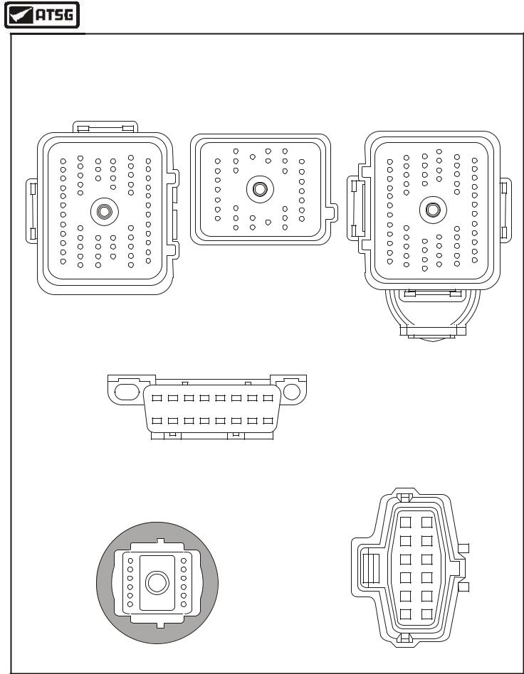
VARIOUS CONNECTOR AND PIN IDENTIFICATION |
|
|
||||
|
(All Connector Views Are Looking Into Connectors With Connector Removed) |
||||||||
PCM Connector |
PCM Connector |
PCM Connector |
|||||||
Number 175A |
|
Number 175B |
Number 175C |
||||||
|
|
|
|
8 |
17 |
20 |
|
31 |
|
13 |
23 |
30 |
37 |
1 |
14 |
26 |
13 |
23 |
39 |
1 |
47 |
|
1 |
|
49 |
||||
|
|
|
|
10 |
|
22 |
|
|
|
|
25 |
|
|
|
|
|
|
34 |
|
|
|
33 |
|
|
|
|
|
26 |
|
17 |
|
41 |
|
|
|
17 |
|
43 |
|
|
|
|
|
|
|
||||
|
|
|
|
11 |
|
23 |
|
|
|
|
|
|
|
7 |
19 |
32 |
|
|
|
|
|
|
|
|
25 |
|
|
|
|
18 |
|
|
42 |
13 |
16 |
18 |
|
44 |
|
|
26 |
34 |
|
|
|
|
|
35 |
|
|
|
|
|
|
|
|
|
27 |
|
12 |
|
36 |
58 |
|
|
|
12 |
|
60 |
29 |
|
|
|
|
38 |
||||
22 |
|
46 |
|
|
|
22 |
48 |
||
|
|
|
|
|
|
|
|
30 |
|
|
|
|
|
(PCM LOCATION, ENGINE COMPARTMENT - RH SIDE) |
|
|
|||
|
|
|
|
Data Link |
|
|
|
|
|
|
|
|
|
Connector |
|
|
|
|
|
|
|
|
|
1 |
|
8 |
|
|
|
|
|
|
|
9 |
|
16 |
|
|
|
|
|
|
|
|
|
|
Digital Transmission |
||
|
|
|
|
|
|
|
Range Sensor Connector |
||
|
|
|
Solenoid Body |
|
|
|
|
|
|
|
|
|
Connector |
|
|
|
|
|
|
|
|
|
|
|
|
|
1 |
7 |
|
|
|
|
|
|
|
|
2 |
8 |
|
|
|
11 |
|
1 |
|
|
3 |
9 |
|
|
|
|
|
|
|
|
4 |
10 |
|
|
|
16 |
|
6 |
|
|
5 |
11 |
|
|
|
|
|
|
|
|
|
||
|
|
|
|
|
|
|
6 |
12 |
|
|
|
|
|
|
|
|
|
Copyright © 2004 ATSG |
|
Figure 8
12 |
AUTOMATIC TRANSMISSION SERVICE GROUP |
|
Technical Service Information
PCM |
|
|
|
|
|
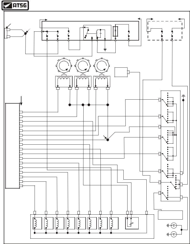
WIRING SCHEMATIC FOR EXPLORER/MOUNTAINEER |
|
HOT IN START |
HOT IN START |
|
||||||||||||||||||||||
Connector |
|
|
|
|
|
|
|
|
|
|
|
|
|
|
|
|
|
|
|
HOT IN START OR RUN |
|
|
||||||||||
|
|
|
|
|
HOT AT ALL TIMES |
|
|
|
|
|
|
|
|
|
|
|
|
OR RUN |
|
|
ONLY |
|
|
|||||||||
No. 175A |
|
|
|
|
|
|
|
|
|
|
|
|
|
|
|
|
|
|
|
|
|
|
|
|
|
|
|
|
||||
|
Splice |
|
|
|
|
|
BATTERY JUNCTION BOX (UNDERHOOD) |
|
|
|
|
|
|
|
|
|
CENTRAL JUNCTION BOX |
|
|
|||||||||||||
|
|
|
|
|
|
|
|
|
|
|
|
|
PCM POWER |
|
|
|
|
|
|
|
|
|
|
|
|
|
|
|
|
|||
|
Violet |
|
S130 |
|
|
|
|
|
|
|
|
|
|
|
|
|
|
|
|
|
|
|
|
|
|
|
|
|
|
|||
32 |
|
|
|
|
|
|
|
|
|
|
|
|
|
RELAY |
|
|
|
|
PCM |
|
|
|
|
|
|
|
|
|
|
|
||
|
|
|
|
|
|
|
|
|
|
|
|
|
|
|
|
|
|
|
|
|
|
|
|
|
|
FUSE |
|
FUSE |
|
|
||
|
|
|
|
|
|
|
FUSE |
|
FUSE |
|
FUSE |
|
|
|
|
|
|
|
|
|
DIODE |
|
FUSE |
|
|
|
|
|
|
|||
|
|
|
|
|
|
|
|
|
Dk Green/Orange |
|
|
|
|
|
|
|
|
|
|
|
|
F27 (7.5A) |
F29 (10A) |
|
||||||||
|
Violet |
|
|
|
|
|
F-37 |
|
F-40 |
|
F-11 |
|
|
|
|
|
|
|
|
|
|
F-41 |
|
|
|
|
|
|||||
33 |
|
|
|
|
|
|
|
|
|
|
|
|
|
|
|
|
|
|
|
|
|
|
|
|
|
|
||||||
|
|
|
|
|
|
15A |
|
15A |
|
40A |
|
|
|
|
|
|
|
|
|
|
15A |
|
|
|
|
|
|
|
|
|
||
|
|
Violet |
Red |
|
|
Violet/Yellow |
|
Violet |
|
|
|
|
Red |
|
|
Black |
|
|
Tan/Black |
|
|
|
|
|
|
|
|
|
|
|
|
|
|
|
|
|
|
|
|
|
|
|
|
|
|
|
|
|
|
|
|
|
|
4WD |
|
|
|
|
|
Orange |
|
Red/Lt Blue |
|
|
|
|
|
|
|
|
|
|
|
|
|
|
|
|
|
|
|
|
|
|
|
|
|
Red/White |
|
|
|
|
|
|
|
|
||
|
|
|
|
|
|
|
|
|
|
|
|
|
|
|
|
|
|
|
|
|
CONTROL |
11 |
|
|
|
|
|
|
|
|
||
|
|
|
|
|
|
|
|
|
|
|
|
|
|
|
|
|
|
|
|
|
|
|
|
|
|
|
|
|
|
|
||
|
|
|
|
|
|
|
|
|
|
|
|
|
|
|
|
|
|
|
|
|
MODULE |
|
|
|
|
|
|
|
|
|
|
|
|
|
|
|
|
|
|
|
|
Turbine |
|
|
|
Output |
|
|
Intermediate |
|
|
|
|
|
|
|
|
|
|
|
|
|
|
||
|
|
|
|
|
|
|
|
|
Speed |
|
|
|
Speed |
|
|
Speed |
|
|
|
|
|
|
|
|
|
|
|
|
Red/Lt Blue |
|||
|
PCM "Center" |
|
|
|
|
|
Sensor |
|
|
|
Sensor |
|
|
Sensor |
|
|
|
|
|
|
|
|
|
|
|
|
||||||
|
|
|
|
|
|
|
|
|
|
|
|
|
|
|
|
|
|
|
|
|
|
|
|
|
|
|||||||
|
|
|
|
|
1 |
|
|
2 |
1 |
|
2 |
1 |
|
|
|
2 |
|
|
|
|
|
|
|
|
|
|
|
|
|
|||
|
Connector |
|
|
|
|
|
|
|
|
|
|
|
|
|
|
|
|
|
|
|
|
|
|
|
||||||||
|
|
|
|
|
Dk Green/White |
|
Gray/Red |
|
Dk Blue/Yellow |
|
Gray/Red |
Yellow/Lt Green |
|
|
Gray/Red |
|
|
|
|
|
|
|
|
|
R N D 3/ 2 1 |
|
|
|
|
|||
|
No. 175B |
|
|
|
|
|
|
|
|
|
|
|
|
|
|
|
|
|
|
4 |
|
|
|
|||||||||
|
|
|
|
|
|
|
|
|
|
|
|
|
|
|
|
|
|
|
|
Yellow/Black |
4 |
|
|
G102 |
||||||||
|
|
|
|
|
|
|
|
|
|
|
|
|
|
|
|
|
|
|
|
|
|
|
||||||||||
PCM |
|
|
|
|
|
|
|
|
|
|
|
|
|
|
Gray/Red |
|
|
|
|
|
|
|
|
|
|
P |
|
|
|
|
||
|
|
|
|
|
|
|
|
|
|
|
Gray/Red |
|
|
|
|
|
|
|
|
|
|
|
|
|
|
|
|
|
||||
|
Dk Green/White |
|
|
|
|
|
|
|
|
|
|
|
|
|
|
|
|
|
|
|
|
|
|
D 3/ 2 1 |
|
|
|
|
||||
|
TSS |
27 |
|
|
|
|
|
|
|
|
|
|
|
|
|
|
|
|
|
|
|
|
|
|
|
|
|
|
||||
|
|
|
|
|
|
|
|
|
|
|
|
|
|
|
|
|
|
|
|
|
|
|
|
|
4 |
|
|
|
||||
|
OSS |
26 |
Dk Blue/Yellow |
|
|
|
|
|
|
|
|
|
|
|
|
|
|
|
|
|
|
|
|
Lt Blue/Black |
5 |
|
|
|
||||
|
Orange/Black |
|
|
|
|
|
|
|
|
|
|
|
|
|
|
|
|
|
|
|
|
|
|
|
N |
|
|
|
|
|||
CONTROL MODULE |
|
23 |
|
|
|
|
|
|
|
|
|
|
|
|
|
|
|
|
|
|
|
|
|
|
|
R |
|
|
|
|
||
|
|
|
|
|
|
|
|
|
|
|
|
|
|
|
|
|
|
|
|
|
|
|
|
2 1 P R N D 3/ 2 1 P |
|
|
|
|
||||
|
|
|
|
|
|
|
|
|
|
|
|
|
|
|
|
|
|
|
|
|
|
|
|
|
|
|
|
|
|
|||
TR1 |
22 |
Yellow/Black |
|
|
|
|
|
|
|
|
|
|
|
|
|
|
|
|
|
|
|
|
|
Gray/Red |
3 2 |
|
|
|
|
|||
|
|
|
|
|
|
|
|
|
|
|
|
|
|
|
|
|
|
|
|
|
|
|
|
|
|
|
||||||
ISS |
21 |
Yellow/Lt Green |
|
|
|
|
|
|
|
|
|
|
|
Splice |
|
|
|
|
|
|
|
|
|
|
|
|
||||||
|
|
|
|
|
|
|
|
|
|
|
|
|
|
|
|
|
|
|
|
|
|
|
|
|
||||||||
|
|
Lt Blue/Black |
|
|
|
|
|
|
|
|
|
|
|
|
|
|
|
|
|
|
|
|
|
|
|
|||||||
TR2 |
18 |
|
|
|
|
|
|
|
|
|
|
|
S101 |
|
|
|
|
|
|
|
Lt Blue/Yellow |
4 |
|
|
|
|||||||
|
|
|
|
|
|
|
|
|
|
|
|
|
|
|
|
|
|
|
|
|
|
|
|
|
||||||||
|
|
Gray/Red |
|
|
|
|
|
|
|
|
|
|
|
|
|
|
|
|
|
|
|
|
|
|
|
|
||||||
|
17 |
|
|
|
|
|
|
|
|
|
|
|
|
|
|
|
|
|
|
|
|
|
|
|
|
|
|
|||||
|
|
|
|
|
|
|
|
|
|
|
|
|
|
|
|
|
|
|
|
|
|
|
|
|
|
|
|
|||||
|
13 |
Lt Blue/Pink |
|
|
|
|
|
|
|
|
|
|
|
|
|
|
|
|
|
|
|
|
|
|
|
|
|
|||||
|
|
|
|
|
|
|
|
|
|
|
|
|
|
|
|
|
|
|
|
|
|
|
|
|
|
|
|
|||||
|
12 |
White |
|
|
|
|
|
|
|
|
|
|
|
|
|
|
|
|
|
|
|
|
|
|
|
|
|
|
||||
POWERTRAIN |
|
|
|
|
|
|
|
|
|
|
|
|
|
|
|
|
|
|
|
|
|
|
|
|
|
|
3/ 2 1 P R N D 3/ |
4 4 |
|
|
|
|
TR4 |
10 |
White/Black |
|
|
|
|
|
|
|
|
|
|
|
|
|
|
|
|
|
|
|
|
White/Black |
6 |
|
|
|
|||||
|
|
|
|
|
|
|
|
|
|
|
|
|
|
|
|
|
|
|
|
|
|
|
|
|
Black/Lt Blue |
|
||||||
TR3A |
9 |
Lt Blue/Yellow |
|
|
|
|
|
|
|
|
|
|
|
|
|
|
|
|
|
|
|
|
|
|
|
Red/Lt Blue |
||||||
|
|
|
|
|
|
|
|
|
|
|
|
|
|
|
|
|
|
|
|
|
|
|
|
|
||||||||
|
7 |
White/Yellow |
|
|
|
|
|
|
|
|
|
|
|
|
|
|
|
|
|
|
|
|
|
|
|
|||||||
|
|
|
|
|
|
|
|
|
|
|
|
|
|
|
|
|
|
|
|
|
|
|
|
|
|
|||||||
|
5 |
Violet/Yellow |
|
|
|
|
|
|
|
|
|
|
|
|
|
|
|
|
|
|
|
|
|
|
|
|||||||
|
|
|
|
|
|
|
|
|
|
|
|
|
|
|
|
|
|
|
|
|
|
|
|
Red/White |
|
|||||||
|
|
|
|
|
|
|
|
|
|
|
|
|
|
|
|
|
|
|
|
|
|
|
|
|
|
|||||||
|
|
4 |
Brown/Orange |
|
|
|
|
|
|
|
|
|
|
|
|
|
|
|
|
|
|
|
|
|
8 |
D |
|
|
|
|
||
|
|
|
|
|
|
|
|
|
|
|
|
|
|
|
|
|
|
|
|
|
|
|
|
|
N |
|
|
7 |
|
|||
|
|
|
|
|
|
|
|
|
|
|
|
|
|
|
|
|
|
|
|
|
|
|
|
|
|
|
|
|
|
|||
|
|
3 |
Pink/Black |
|
|
|
|
|
|
|
|
|
|
|
|
|
|
|
|
|
|
|
|
|
|
|
P R |
|
2 1 |
|
|
|
|
|
2 |
Violet/Orange |
|
|
|
|
|
|
|
|
|
|
|
|
|
|
|
|
|
|
|
|
|
Orange |
|
|
|
3/ |
4 |
|
|
PCM |
|
|
|
|
|
|
|
|
|
|
|
|
|
|
|
|
|
|
|
|
|
9 |
|
|
D |
|
|
|||||
|
|
|
|
|
|
|
|
|
|
|
|
|
|
|
|
|
|
|
|
|
|
|
|
|
|
|
||||||
|
|
|
|
|
|
|
|
|
|
|
|
|
|
|
|
|
|
|
|
|
|
|
|
|
|
|
|
|||||
Orange/Yellow |
|
|
|
|
|
|
|
|
|
|
|
|
|
|
|
|
|
|
|
|
|
|
|
|
1 |
|
R N |
12 |
|
|||
1 |
|
|
|
|
|
|
|
|
|
|
|
|
|
|
|
|
|
|
|
|
|
|
|
|
|
|
|
|||||
|
|
|
|
|
|
|
|
|
|
|
|
|
|
|
|
|
|
|
|
|
|
|
|
|
|
|
|
2 |
|
P |
|
|
|
|
|
|
|
|
|
|
|
|
|
|
|
|
|
|
|
|
|
|
|
|
|
|
|
|
|
|
3/ |
4 |
|
|
|
|
|
|
|
|
|
|
|
|
Brown/Orange |
|
|
White/Yellow |
|
|
|
|
|
|
|
|
|
|
|
|
|
White/Pink |
10 |
N D |
|
|
|
|
|
|
|
Orange/Yellow |
|
|
Violet/Orange |
|
Pink/Black |
|
|
|
Lt Blue/Pink |
|
|
|
|
Violet/Yellow |
|
|
|
Orange/Black |
|
Violet/Yellow |
|
R |
|
|
11 |
|
|||
|
|
|
|
|
|
|
|
|
|
White |
|
|
|
|
Gray/Red |
|
|
P |
|
|
|
|
||||||||||
|
|
|
|
|
|
|
|
|
|
|
|
|
|
|
Digital Transmission |
|
||||||||||||||||
|
|
|
|
|
|
|
|
|
|
|
|
|
|
|
Range (DTR) Sensor |
|
||||||||||||||||
|
|
|
|
|
|
|
|
|
|
|
|
|
|
|
|
|
|
|
|
|
||||||||||||
|
|
|
16 |
|
|
15 |
|
6 |
|
5 |
|
11 |
|
1 |
|
4 |
|
|
14 |
|
|
12 |
2 |
|
|
3 |
|
Starter Relay |
|
Black/Pink |
||
|
|
|
|
|
|
|
|
|
|
|
|
|
|
|
|
|
Located in Battery |
|
||||||||||||||
|
|
|
|
Solenoid "A" |
Shift Solenoid "B" |
Shift Solenoid "C" |
Shift Solenoid "D" |
Pressure Control "A" |
Pressure Control "B" |
|
Control "C" |
|
|
|
|
Junction Box (Underhood) |
||||||||||||||||
|
|
|
Shift |
Pressure |
TCC |
Solenoid |
TFT Sensor |
|
Reverse |
|
|
|
||||||||||||||||||||
|
|
|
|
|
|
|
|
|
|
|
|
|
|
|
|
|
|
|
|
|
|
|
|
|
|
|
|
|
|
|
||
|
|
|
|
|
|
|
|
|
|
|
|
|
|
|
|
|
|
|
|
|
|
|
|
|
|
|
|
Lamps |
|
|
|
|
|
|
|
|
|
|
|
|
|
|
|
|
AUTOMATIC TRANSMISSION |
|
|
|
|
Copyright © 2004 ATSG |
|
||||||||||||||
|
|
|
|
|
|
|
|
|
|
|
|
|
|
|
|
|
|
|
|
|
|
|
|
|
|
|
||||||
Figure 9
AUTOMATIC TRANSMISSION SERVICE GROUP |
13 |
|
Technical Service Information
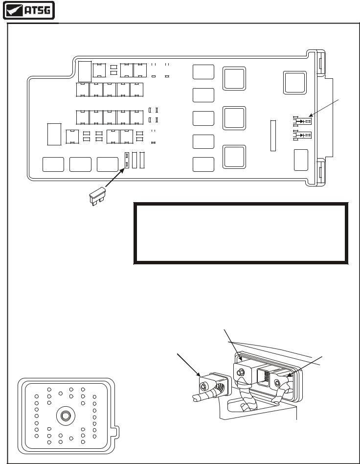
PCM Connector
Number 175B
8 |
14 |
17 |
20 |
|
1 |
|
26 |
||
|
|
|||
10 |
|
|
22 |
|
11 |
|
|
23 |
|
7 |
|
19 |
32 |
|
13 |
16 |
25 |
||
|
Solenoid Body
Connector
11 |
1 |
16 |
6 |
Digital Transmission
Range Sensor Connector
1 7
2 8
3 9
4 10
5 11
6 12
PCM CONNECTOR NUMBER 175B
PIN NO. |
TRANSMISSION CIRCUIT FUNCTION ONLY |
1Shift Solenoid "A" (SSA) ground signal from PCM
2Shift Solenoid "B" (SSB) ground signal from PCM
3Shift Solenoid "C" (SSC) ground signal from PCM
4Shift Solenoid "D" (SSD) ground signal from PCM
5Torque Converter Clutch (TCC) ground signal from PCM
7 |
Pressure Control Solenoid "A" (PC A) ground signal from PCM |
9 |
Digital Transmission Range (DTR) Sensor TR3A signal to PCM |
|
|
10 |
Digital Transmission Range (DTR) Sensor TR4 signal to PCM |
12Pressure Control Solenoid "C" (PC C) ground signal from PCM
13Pressure Control Solenoid "B" (PC B) ground signal from PCM
17Sensor signal return (Ground)
18Digital Transmission Range (DTR) Sensor TR2 signal to PCM
21Intermediate Shaft Speed (ISS) Sensor signal to PCM
22Digital Transmission Range (DTR) Sensor TR1 signal to PCM
23Transmission Fluid Temperature (TFT) Sensor signal to PCM
26Output Shaft Speed (OSS) Sensor signal to PCM
27Turbine Shaft Speed (TSS) Sensor signal to PCM
SOLENOID BODY CONNECTOR
PIN NO. |
CIRCUIT FUNCTION |
1Pressure Control Solenoid "B" (PC B) ground signal from PCM
2Transmission Fluid Temperature (TFT) Sensor signal to PCM
3Battery Voltage in from Fuse 37 in Battery Junction Box
4Pressure Control Solenoid "C" (PC C) ground signal from PCM
5Shift Solenoid "D" (SSD) ground signal from PCM
6Shift Solenoid "C" (SSC) ground signal from PCM
11Pressure Control Solenoid "A" (PC A) ground signal from PCM
12Sensor signal return (Ground)
14Torque Converter Clutch (TCC) ground signal from PCM
15Shift Solenoid "B" (SSB) ground signal from PCM
16Shift Solenoid "A" (SSA) ground signal from PCM
DIGITAL TRANS RANGE CONNECTOR
PIN NO. |
CIRCUIT FUNCTION |
2Sensor signal return (Ground)
3Digital Transmission Range (DTR) Sensor TR3A signal to PCM
4Digital Transmission Range (DTR) Sensor TR1 signal to PCM
5Digital Transmission Range (DTR) Sensor TR2 signal to PCM
6Digital Transmission Range (DTR) Sensor TR4 signal to PCM
7Ground wire to G102 ground
8Selector Lever Signal to 4WD Control Module
9Battery Voltage from Fuse F27 in Central Junction Box for reverse lamps
10Battery Voltage to starter relay in Battery Junction Box, in start position only
11Battery Voltage to reverse lamps
12Battery Voltage from Fuse F29 in Central Junction Box for starter circuit
Copyright © 2004 ATSG
Figure 10
14 |
AUTOMATIC TRANSMISSION SERVICE GROUP |
|
Technical Service Information
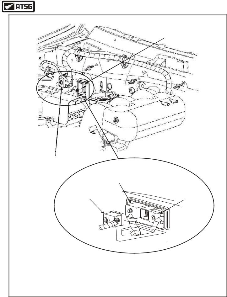
POWERTRAIN
CONTROL MODULE
LOCATION
PCM Connector
Number 175C
PCM Connector
Number 175A
PCM Connector |
PCM Connector |
|
Number 175C |
||
Number 175B |
||
|
Copyright © 2004 ATSG
Figure 11
AUTOMATIC TRANSMISSION SERVICE GROUP |
15 |
|
Technical Service Information
RESISTANCE CHART FOR TRANSMISSION COMPONENTS
Battery Junction Box (Underhood)
F-1 |
F-2 |
F-4 F-5 |
F-9 F-10 F-11 F-12 F-13
F-19 F-20 F-21 F-22 F-23
F-29 |
F-30 |
F-33 F-34 |
F-38 |
F-39 |
|
|
|
|
|
|
|
|
|
|
|
|
|
|
|
F-6 |
|
F-7 |
|
|
|
|
|
|
|
|||||
|
|
|
|
|
|
|
|
|
|
|
|
|
|
|
|
|
|
|
|
|
|
|
|
|
|
||||
F-14 |
|
F-15 |
|
F-16 |
|
F-17 |
|
|
F-18 |
|
||||
|
|
|
|
|
|
|
|
|
|
|
||||
|
|
|
|
|
|
|
|
|
|
|||||
|
|
|
|
F-26 |
|
F-27 |
|
|
F-28 |
|
||||
|
|
|
|
|
|
|
|
|
|
|
|
|
|
|
|
|
|
|
|
|
|
|
|
|
|
|
|
|
|
F-36 |
|
|
|
|
|
F-42 |
|
|
||||||
|
|
|
|
|
|
|
|
|
|
|
|
|||
|
|
|
|
|
|
|
|
F-43 |
|
|
||||
|
|
|
|
|
|
|
|
|
|
|
|
|
|
|
|
|
|
|
|
|
|
|
F-44 |
|
|
||||
|
|
|
|
|
|
|
|
|
|
|
|
|
|
|
F-40 |
|
F-41 |
|
|
|
|
|
F-45 |
|
|
||||
|
|
|
|
|
|
|
|
|
|
|
|
|
||
|
|
|
|
|
|
|
|
F-46 |
|
|
||||
|
|
|
|
|
|
|
|
|
|
|
|
|
|
|
Ignition
Relay
A/C Clut |
Starter |
|
Relay |
||
Relay |
||
|
PCM
Brake
Power
Pedal
Relay
Relay
PCM
Power
Diode
A 15
Remove 15 Amp
Fuse F-37
Transmission Component Resistance Checks
Through PCM Connector 175B
1.Remove Fuse 37 from Battery Junction Box, as shown.
2.Remove PCM Connector 175B, as shown below.
3.Use resistance chart found in Figure 13 for pin numbers.
Remove PCM Connector
(Center) Number 175B
PCM Connector
Number 175A
|
|
|
PCM Connector |
PCM Connector |
|
PCM Connector |
Number 175C |
||
|
Number 175B |
|||
|
Number 175B |
|
||
|
|
|
||
|
(Face View) |
|
|
|
8 |
17 |
20 |
|
|
1 |
14 |
26 |
|
|
|
|
|
||
10 |
|
22 |
|
|
11 |
|
23 |
|
|
7 |
19 |
32 |
|
|
|
25 |
|
|
|
13 |
16 |
|
|
|
Copyright © 2004 ATSG
Figure 12
16 |
AUTOMATIC TRANSMISSION SERVICE GROUP |
|
Technical Service Information
RESISTANCE CHART FOR TRANSMISSION COMPONENTS |
||
COMPONENT RESISTANCE CHART THROUGH PCM CONNECTOR |
||
Component |
Pin Numbers |
Resistance |
Shift Soleniod "A" |
175B, Term 1 and F-37 Cavity |
16-45 Ohms |
Shift Soleniod "B" |
175B, Term 2 and F-37 Cavity |
16-45 Ohms |
Shift Soleniod "C" |
175B, Term 3 and F-37 Cavity |
16-45 Ohms |
Shift Soleniod "D" |
175B, Term 4 and F-37 Cavity |
16-45 Ohms |
PC Soleniod "A" |
175B, Term 7 and F-37 Cavity |
3.3-7.5 Ohms |
PC Soleniod "B" |
175B, Term 13 and F-37 Cavity |
3.3-7.5 Ohms |
PC Soleniod "C" |
175B, Term 12 and F-37 Cavity |
3.3-7.5 Ohms |
TCC Soleniod |
175B, Term 5 and F-37 Cavity |
9-16 Ohms |
TFT Sensor |
175B, Term 17 and Term 23 |
See Chart Below |
|
|
|
Turbine Speed Sensor |
175B, Term 17 and Term 27 |
325-485 Ohms @ 70°F |
Intermediate Speed Sensor |
175B, Term 17 and Term 21 |
325-485 Ohms @ 70°F |
Output Speed Sensor |
175B, Term 17 and Term 26 |
325-485 Ohms @ 70°F |
CASE CONNECTOR PIN IDENTIFICATION |
|
||||
|
AND RESISTANCE CHARTS |
|
|||
Solenoid Resistance Chart |
|
|
TFT Sensor Resistance Chart |
||
|
Connector |
Resistance |
|
0°F-31°F = 284k - 100k Ohms |
|
Component |
Terminals |
In Ohms |
|
|
|
|
32°F-68°F = 100k - 37k Ohms |
||||
Shift Solenoid "A" |
3 And 16 |
16-45 |
|
|
|
|
69°F-104°F = 37k - 16k Ohms |
||||
Shift Solenoid "B" |
3 And 15 |
16-45 |
|
|
|
|
105°F-158°F = 16k - 5k Ohms |
||||
Shift Solenoid "C" |
3 And 6 |
16-45 |
|
|
|
|
159°F-194°F = 5k - 2.7k Ohms |
||||
Shift Solenoid "D" |
3 And 5 |
16-45 |
|
|
|
|
195°F-230°F = 2.7k - 1.5k Ohms |
||||
Pressure Control Solenoid "A" |
3 And 11 |
3.3-7.5 |
|
|
|
|
231°F-266°F = 1.5k - 0.8k Ohms |
||||
Pressure Control Solenoid "B" |
3 And 1 |
3.3-7.5 |
|
|
|
|
267°F-302°F = 0.8k - 0.54k Ohms |
||||
Pressure Control Solenoid "C" |
3 And 4 |
3.3-7.5 |
|
|
|
|
|
Transmission |
|||
TCC Solenoid |
3 And 14 |
9-16 |
|
|
|
|
Case Connector |
||||
|
|
|
|
||
|
|
|
|
|
|
TOT Sensor |
2 And 12 |
See Chart |
|
|
|
|
|
|
11 |
1 |
|
|
|
|
16 |
6 |
|
Copyright © 2004 ATSG
Figure 13
AUTOMATIC TRANSMISSION SERVICE GROUP |
17 |
|

|
Technical Service Information |
|
DIAGNOSTIC TROUBLE CODE (DTC) CHART AND DESCRIPTIONS |
DTC |
DESCRIPTION |
P0102 |
Mass Air Flow (MAF) sensor system concerns |
P0103 |
Mass Air Flow (MAF) sensor system concerns |
P0112 |
Intake Air Temperature (IAT) sensor indicates 254°F (Grounded Circuit) |
P0113 |
Intake Air Temperature (IAT) sensor indicates -40°F (Open Circuit) |
P0114 |
Intake Air Temperature (IAT) sensor out of "On-Board Diagnostic" range |
P0116 |
Engine Coolant Temperature (ECT) sensor out of "On-Board Diagnostic" range |
P0117 |
Engine Coolant Temperature (ECT) sensor indicates 254°F (Grounded Circuit) |
P0118 |
Engine Coolant Temperature (ECT) sensor indicates -40°F (Open Circuit) |
P0121 |
Throttle Position (TP) sensor system intermittent |
P0122 |
Throttle Position (TP) sensor signal less than self test minimum |
P0123 |
Throttle Position (TP) sensor signal more than self test maximum |
P0300 |
Electronic Ignition (EI) multiple cylinder miss-fire or defective crank sensor |
P0308 |
Electronic Ignition (EI) missfire cylinder 8 |
P0320 |
Electronic Ignition (EI) two successive erratic PIP pulses have occured |
P0340 |
Electronic Ignition (EI) camshaft position sensor fault |
P0500 |
Vehicle Speed Sensor (VSS), insufficient input from ABS through SCP link |
P0503 |
Vehicle Speed Sensor (VSS), poor performance or noisy signal |
P0705 |
Digital Transmission Range (DTR) sensor circuit failure |
P0708 |
Digital Transmission Range (DTR) sensor circuit TR3A Open |
P0712 |
Transmission Fluid Temperature (TFT) circuit grounded, 315°F indicated |
P0713 |
Transmission Fluid Temperature (TFT) circuit open, -40°F indicated |
P0715 |
Turbine Shaft Speed (TSS) sensor, insufficient input |
P0717 |
Turbine Shaft Speed (TSS) intermittent sensor signal |
P0718 |
Turbine Shaft Speed (TSS) sensor signal noisy |
P0720 |
Output Shaft Speed (OSS) sensor, insufficient input |
P0721 |
Output Shaft Speed (OSS) sensor signal noisy |
P0722 |
Output Shaft Speed (OSS) intermittent sensor signal |
P0731 |
Gear Ratio Error, 1st Gear |
P0732 |
Gear Ratio Error, 2nd Gear |
P0733 |
Gear Ratio Error, 3rd Gear |
P0734 |
Gear Ratio Error, 4th Gear |
P0735 |
Gear Ratio Error, 5th Gear |
P0740 |
Torque Converter Clutch (TCC) circuit open or shorted |
P0741 |
Torque Converter Clutch (TCC) slippage detected |
Copyright © 2004 ATSG
Figure 14
18 |
AUTOMATIC TRANSMISSION SERVICE GROUP |
|

|
Technical Service Information |
|
DIAGNOSTIC TROUBLE CODE (DTC) CHART AND DESCRIPTIONS |
DTC |
DESCRIPTION |
P0743 |
Torque Converter Clutch (TCC) solenoid circuit failure during KOEO test |
P0745 |
Pressure Control "A" (PCA) solenoid, shorted circuit |
P0748 |
Pressure Control "A" (PCA) solenoid, mechanical failure |
P0750 |
Shift Solenoid "A" (SSA) circuit failure during KOEO test |
P0753 |
Shift Solenoid "A" (SSA) circuit failure open or shorted |
P0755 |
Shift Solenoid "B" (SSB) circuit failure during KOEO test |
P0758 |
Shift Solenoid "B" (SSB) circuit failure open or shorted |
P0760 |
Shift Solenoid "C" (SSC) circuit failure during KOEO test |
P0763 |
Shift Solenoid "C" (SSC) circuit failure, open or shorted |
P0765 |
Shift Solenoid "D" (SSD) circuit failure during KOEO test |
P0768 |
Shift Solenoid "D" (SSD) circuit failure open or shorted |
P0775 |
Pressure Control "B" (PCB) solenoid, shorted circuit |
P0778 |
Pressure Control "B" (PCB) solenoid, mechanical failure |
P0779 |
Pressure Control "B" (PCB) solenoid, intermittent short to ground |
P0791 |
Intermediate Shaft Speed (ISS) sensor signal failure |
P0794 |
Intermediate Shaft Speed (ISS) sensor signal intermittent |
P0795 |
Pressure Control "C" (PCC) solenoid, shorted circuit |
P0796 |
Pressure Control "C" (PCC) solenoid, open circuit |
P0797 |
Pressure Control "C" (PCC) solenoid failure |
P0798 |
Pressure Control "C" (PCC) solenoid, mechanical failure |
P0799 |
Pressure Control "C" (PCC) solenoid, intermittent short to ground |
P0960 |
Pressure Control "A" (PCA) solenoid, circuit open |
P0962 |
Pressure Control "A" (PCA) solenoid, shorted to ground |
P0963 |
Pressure Control "A" (PCA) solenoid, intermittent short to power or ground |
P0964 |
Pressure Control "B" (PCB) solenoid, open circuit |
P0966 |
Pressure Control "B" (PCB) solenoid, shorted to ground |
P0967 |
Pressure Control "B" (PCB) solenoid, intermittent short to power or ground |
P0968 |
Pressure Control "C" (PCC) solenoid, open circuit |
P0970 |
Pressure Control "C" (PCC) solenoid, shorted to ground |
P0971 |
Pressure Control "C" (PCC) solenoid, intermittent short to power or ground |
P1100 |
Mass Air Flow (MAF) sensor, circuit intermittent voltage input |
P1101 |
Mass Air Flow (MAF) sensor, signal was not 0.34-1.96 during self test |
P1120 |
Throttle Position (TP) sensor signal went to less than .49 volts |
P1121 |
Throttle Position (TP) sensor signal inconsistant with MAF signal |
Copyright © 2004 ATSG
Figure 15
AUTOMATIC TRANSMISSION SERVICE GROUP |
19 |
|

|
Technical Service Information |
|
DIAGNOSTIC TROUBLE CODE (DTC) CHART AND DESCRIPTIONS |
DTC |
DESCRIPTION |
P1124 |
Throttle Position (TP) sensor not in proper position for KOEO test |
P1125 |
Throttle Position (TP) sensor signal went to more than 4.60 volts |
P1351 |
Electronic Ignition (EI) concerns |
P1364 |
Electronic Ignition (EI) concerns |
P1460 |
Air Conditioning (AC) clutch cycling pressure switch error |
P1572 |
Brake Pedal Position (BPP) switch, circuit failed |
P1636 |
SSx ISIG communication error (Replace PCM) |
P1700 |
Internal transmission component failure |
P1702 |
Digital Transmission Range (DTR) sensor signal intermittent |
P1703 |
Brake Pedal Position (BPP) not cycled during KOER test, or switch circuit failed |
P1704 |
Digital Transmission Range (DTR) sensor, not in P or N during KOEO/KOER |
P1705 |
Digital Transmission Range (DTR), not in P or N during KOEO/KOER or circuit failure |
P1711 |
Transmission Fluid Temperature (TFT) out of On-Board diagnostic range |
P1713 |
Transmission Fluid Temperature (TFT), no change in TFT low range |
P1714 |
Shift Solenoid "A" (SSA), mechanical failure of solenoid detected |
P1715 |
Shift Solenoid "B" (SSB), mechanical failure of solenoid detected |
P1716 |
Shift Solenoid "C" (SSC), mechanical failure of solenoid detected |
P1717 |
Shift Solenoid "D" (SSD), mechanical failure of solenoid detected |
P1718 |
Transmission Fluid Temperature (TFT), no change in TFT high range |
P1740 |
Torque Converter Clutch (TCC), mechanical failure of solenoid detected |
P1746 |
Pressure Control "A" (PCA) solenoid, open circuit |
P1747 |
Pressure Control "A" (PCA) solenoid, shorted circuit |
P1760 |
Pressure Control "A" (PCA) solenoid, intermittent short to ground |
P1780 |
Transmission Control Switch (TCS) input incorrect, no OD cancel when moved |
P1783 |
Transmission Fluid Temperature (TFT), overtemp condition indicated |
P1788 |
Pressure Control "B" (PCB) solenoid, open circuit |
P1789 |
Pressure Control "B" (PCB) solenoid, shorted circuit |
|
|
|
|
|
|
|
|
|
|
|
|
|
|
Copyright © 2004 ATSG
Figure 16
20 |
AUTOMATIC TRANSMISSION SERVICE GROUP |
|