

5R55W
.pdfTechnical Service Information
DIRECT CLUTCH ASSEMBLY (Cont'd)
15.Install the direct clutch backing plate, as shown in Figure 82.
16.Install the direct clutch backing plate snap ring, as shown in Figure 82 and ensure that it is fully seated in the groove (See Figure 82).
17.Install dial indicator on top of backing plate, as shown in Figure 83, and check the direct clutch clearance. Should be 1.3-2.0mm (.051"-.079"), as shown in Figure 83.
18.Change the selective backing plate snap ring as necessary, using the chart in Figure 83, to get the proper direct clutch clearance.
19.Set the completed direct clutch housing aside for the final assembly process.
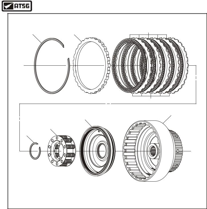
DIRECT CLUTCH
RETURN SPRING
RETAINER SNAP RING
DIRECT CLUTCH
RETURN SPRING
RETAINER
DIRECT CLUTCH
PISTON RETURN
SPRINGS (20)
DIRECT CLUTCH
HOUSING ASSEMBLY
8
Copyright © 2004 ATSG
DIRECT CLUTCH |
BACKING PLATE |
SNAP RING |
"Selective" Snap Ring |
DIRECT CLUTCH |
BACKING PLATE |
DIRECT CLUTCH |
INSIDE SPLINE |
PLATES (5 Req) |
DIRECT CLUTCH |
OUTSIDE SPLINE |
PLATES (5 Req) |
DIRECT CLUTCH |
HOUSING |
8 |
Copyright © 2004 ATSG |
Figure 81 |
Figure 82 |
AUTOMATIC TRANSMISSION SERVICE GROUP |
51 |
|

Technical Service Information
CHECKING DIRECT CLUTCH CLEARANCE |
|||
CLEARANCE SHOULD BE 1.3 - 2.0mm (.051"-.079") |
|||
|
10 |
0 |
10 |
|
|
||
|
20 |
|
20 |
|
30 |
|
30 |
|
40 |
|
40 |
|
50 |
0 |
50 |
|
|
|
8 |
|
Thickness |
||
Part Number |
mm |
|
in |
E860126-S |
1.37 |
|
.054" |
E860127-S |
1.73 |
|
.068" |
E860128-S |
2.08 |
|
.082" |
E860129-S |
2.44 |
|
.096" |
|
Copyright © 2004 ATSG |
||
Figure 83
ENSURE RINGS ROTATE FREELY
Copyright © 2004 ATSG
FORWARD CLUTCH HOUSING ASSEMBLY
1.Disassemble the forward clutch assembly using the illustrations in Figure 86 as a guide.
2.Inspect all forward clutch parts thoroughly for any wear and/or damage.
3.Clean all forward clutch parts thoroughly and dry with compressed air.
4.Install new sealing rings into their grooves on the forward clutch housing (See Figure 85).
5.Ensure that the sealing rings are seated and rotate freely in grooves (See Figure 84).
Continued on Page 54
FORWARD |
CLUTCH |
SEAL RINGS |
FORWARD |
CLUTCH |
HOUSING |
Copyright © 2004 ATSG |
Figure 84 |
Figure 85 |
52 |
AUTOMATIC TRANSMISSION SERVICE GROUP |
|
Technical Service Information
|
|
FORWARD CLUTCH ASSEMBLY EXPLODED VIEW |
||
|
1 |
2 |
|
3 |
|
|
|
||
|
|
|
|
4 |
|
|
|
|
8 |
|
|
7 |
|
|
|
6 |
|
|
|
|
5 |
|
|
|
1. |
FORWARD CLUTCH BACKING PLATE "SELECTIVE" SNAP RING. |
5. |
FORWARD CLUTCH RETURN SPRING RETAINER SNAP RING. |
|
2. |
FORWARD CLUTCH BACKING PLATE. |
|
6. |
FORWARD CLUTCH PISTON RETURN SPRING ASSEMBLY. |
3. |
FORWARD CLUTCH FRICTION PLATES. |
|
7. |
FORWARD CLUTCH PISTON (STAMPED STEEL MOLDED RUBBER). |
4. |
FORWARD CLUTCH STEEL PLATES. |
|
8. |
FORWARD CLUTCH HOUSING. |
|
|
|
|
Copyright © 2004 ATSG |
Figure 86
AUTOMATIC TRANSMISSION SERVICE GROUP |
53 |
|
Technical Service Information
FORWARD CLUTCH HOUSING (Cont'd)
6.Lubricate both inner and outer lip seals on the stamped steel forward clutch piston assembly, as shown in Figure 87, with a small amount of Trans-Jel®.
7.Lubricate both seal surfaces in the housing with a small amount of Trans-Jel® and install the piston assembly with a twisting motion so as not to damage the seals (See Figure 87).
8.Install the return spring retainer assembly on top of the piston, as shown in Figure 88.
9.Compress the return springs and retainer and install the spring retainer snap ring, as shown in Figure 88, and ensure snap ring is seated.
10.Remove the spring compressor.
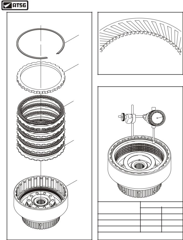
11.Install the forward clutch plates beginning with a steel plate and alternating with friction plates, until you have installed 5 of each, as shown in Figure 89.
CAUTION: Forward Clutch friction plates are directional and must be installed with the grooves facing counterclockwise, as shown in Figure 90. Friction plates should be soaked in Mercon® V for 30 minutes before installing.
12.Install forward clutch backing plate, as shown in Figure 89.
STAMPED STEEL
FORWARD CLUTCH
PISTON AND
CUSHION RING
13.Install forward clutch backing plate snap ring, as shown in Figure 89 and ensure that it is fully seated in the groove.
14.Install dial indicator on top of backing plate, as shown in Figure 91, and check the amount of forward clutch clearance. Clearance should be 1.3 - 2.0mm (.051" - .079") (See Figure 91).
15.Change the selective backing plate snap ring as necessary, using the chart in Figure 91, to get the proper forward clutch clearance.
16.Set the completed forward clutch housing aside for the final assembly process.
FORWARD CLUTCH
SNAP RING
FORWARD CLUTCH |
RETURN SPRING |
RETAINER |
FORWARD CLUTCH
 HOUSING
|
Ensure that snap ring |
FORWARD CLUTCH |
is fully seated |
HOUSING |
|
Copyright © 2004 ATSG |
Copyright © 2004 ATSG |
Figure 87 |
Figure 88 |
54 |
AUTOMATIC TRANSMISSION SERVICE GROUP |
|
Technical Service Information
FORWARD CLUTCH PATTERN DIRECTION
FORWARD CLUTCH
BACKING PLATE
SNAP RING
"Selective" Snap Ring
FORWARD CLUTCH |
CAUTION: Forward Clutch friction plates are |
||||
BACKING PLATE |
directional and must be installed with the grooves |
||||
|
facing counterclockwise, as shown above. |
||||
|
|
Copyright © 2004 ATSG |
|||
|
|
Figure 90 |
|
|
|
FORWARD CLUTCH |
CHECKING FORWARD CLUTCH CLEARANCE |
||||
CLEARANCE SHOULD BE 1.3 - 2.0mm (.051"-.079") |
|||||
FRICTION PLATES |
|||||
(5 REQ) |
|
|
|
|
|
|
|
10 |
0 |
10 |
|
|
|
|
|||
|
|
20 |
|
20 |
|
|
|
30 |
|
30 |
|
|
|
40 |
|
40 |
|
|
|
50 |
0 |
50 |
|
FORWARD CLUTCH |
|
|
|
|
|
STEEL PLATES |
|
|
|
|
|
(5 REQ) |
|
|
|
|
|
FORWARD CLUTCH |
|
|
|
|
|
HOUSING |
|
|
|
|
|
|
|
Thickness |
|||
|
Part Number |
mm |
|
in |
|
|
XW4Z-7D483-AB |
1.73 |
|
.068" |
|
|
XW4Z-7D483-AC |
2.08 |
|
.082" |
|
|
XW4Z-7D483-AD |
2.44 |
|
.096" |
|
Copyright © 2004 ATSG |
|
Copyright © 2004 ATSG |
|||
Figure 89 |
|
Figure 91 |
|
|
|
AUTOMATIC TRANSMISSION SERVICE GROUP |
55 |
|
Technical Service Information
CHECK CENTER SUPPORT BEARING RACE FOR CRACKS |
CENTER SUPPORT |
Ford |
Copyright © 2004 ATSG |
Figure 92
EXAMPLE OF CRACKED RACE WITH BEARING TAKEN OFF
F o r d
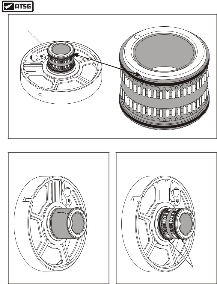
INSTALL NEW SEAL RINGS ON CENTER SUPPORT
Ford


|
CENTER SUPPORT |
|
SEAL RINGS |
Copyright © 2004 ATSG |
Copyright © 2004 ATSG |
Figure 94 |
Figure 95 |
56 |
AUTOMATIC TRANSMISSION SERVICE GROUP |
|
Technical Service Information
CENTER SUPPORT ASSEMBLY
1.The center support assembly will require some extra inspection to ensure it's integrity.
2.Inspect bearing race at the top of the bearing, as shown in Figure 93, for any visable cracks.
3.If there are any visable cracks, replacement of complete center support will be necessary, as the bearing is not available as a service item.
4.We have seen several supports with the bearing race cracked, as shown in Figure 94. This will create leakage of direct and forward clutch oil, into each others circuit.
5.If you cannot visually see any crack, install new sealing rings onto the center support, as shown in Figure 95.
6.The only positive way to verify the integrity of the center support, is to assemble the forward and direct clutch housings, with the appropriate thrust bearings, onto the support, as shown in Figure 96.
7.Now air check the direct and forward clutch passages to ensure these passages are not connected.
Caution: This air check should be performed with every center support assembly, and then replaced as necessary.
8.After you have verified the integrity of center support assembly, set the completed support aside for the final assembly process.
AIR CHECKING CENTER SUPPORT PASSAGES |
||
|
|
8 |
|
Ford |
|
Lube |
Direct |
Forward |
|
Clutch |
Clutch |
|
Copyright © 2004 ATSG |
|
Figure 96
AUTOMATIC TRANSMISSION SERVICE GROUP |
57 |
|
Technical Service Information
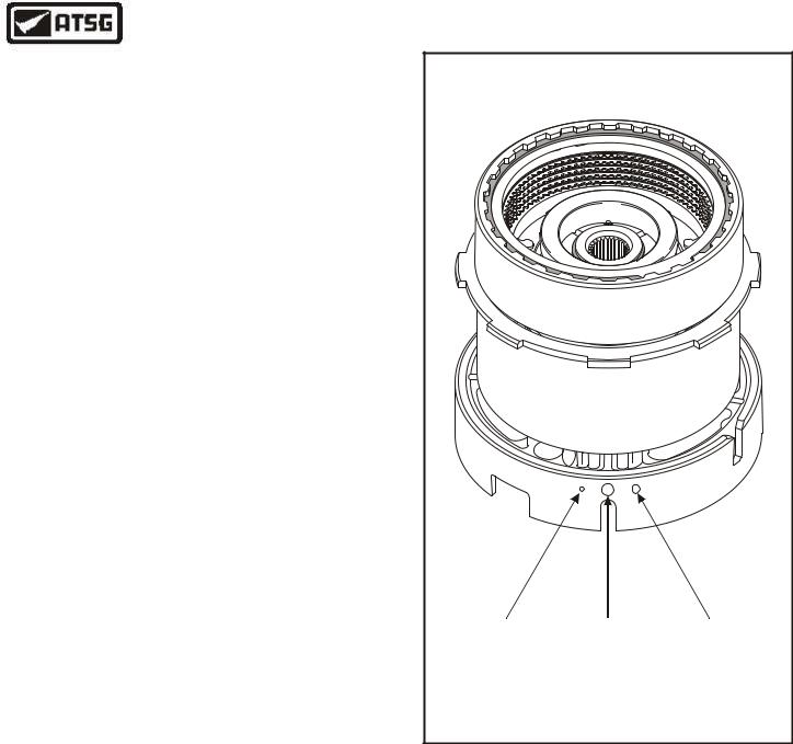
LOW SPRAG AND REVERSE DRUM ASSEMBLY |
REAR RING GEAR AND HUB ASSEMBLY |
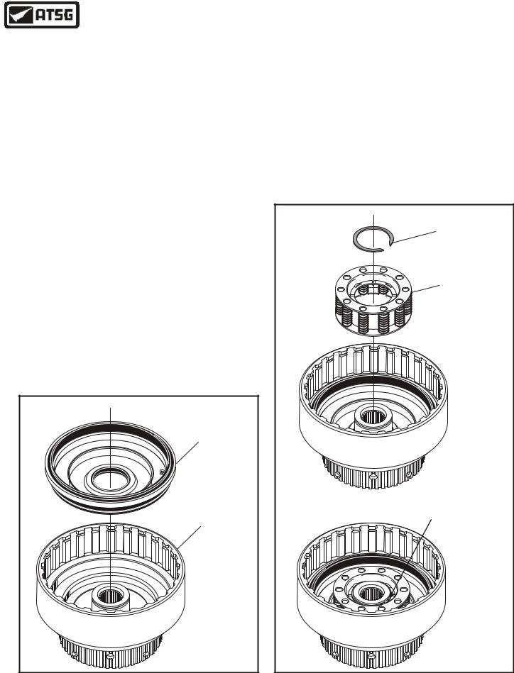
1.The low sprag assembly is not yet available as a service item. If the low sprag or the bearing assembly needs replacement, the complete reverse drum assembly must be purchased.
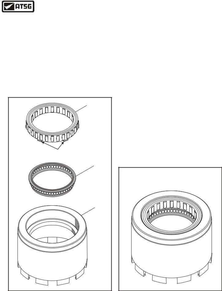
2.If you do take it apart, the bearing assembly must be installed first, in the direction shown in Figure 97.
3.Then install the low sprag assembly, with the tabs facing down, as shown in Figure 97, until it "Snaps" into the groove.
4.After inspection and re-assembly if necessary, set the completed reverse drum assembly aside for the final assembly process (See Figure 98).
LOW SPRAG
ASSEMBLY
TABS FACING
DOWN
CAGED NEEDLE
BEARING ASSEMBLY
REVERSE DRUM
ASSEMBLY
Copyright © 2004 ATSG
Figure 97
1.Inspect all rear ring gear parts thoroughly as shown in Figure 99.
2.Remove and discard the sealing ring on the rear gear hub, as shown in Figure 99.
3.Assemble the rear ring gear hub into the rear ring gear and install the snap ring, as shown in Figure 99.
4.Install a new sealing ring into the groove in the ring gear hub, as shown in Figure 99.
Caution: This sealing ring is manufactured with two small notches in the outside diameter as shown in Figure 100, and must be installed in this location.
5.Set completed rear ring gear and hub assembly, as shown in Figure 101, aside for the final assembly process.
COMPLETED LOW SPRAG AND |
REVERSE DRUM ASSEMBLY |
Copyright © 2004 ATSG |
Figure 98
58 |
AUTOMATIC TRANSMISSION SERVICE GROUP |
|

Technical Service Information
"SPECIAL" SEALING |
RING WITH NOTCHES |
REAR RING GEAR |
TO HUB SNAP RING |
REAR RING |
GEAR HUB |
REAR RING GEAR |
Copyright © 2004 ATSG |
UNIQUE SEALING RING FOR
REAR RING GEAR HUB
Two Notches Made
In Sealing Ring
Copyright © 2004 ATSG
Figure 100
COMPLETED REAR RING GEAR AND HUB |
Copyright © 2004 ATSG |
Figure 99 |
Figure 101 |
AUTOMATIC TRANSMISSION SERVICE GROUP |
59 |
|
Technical Service Information
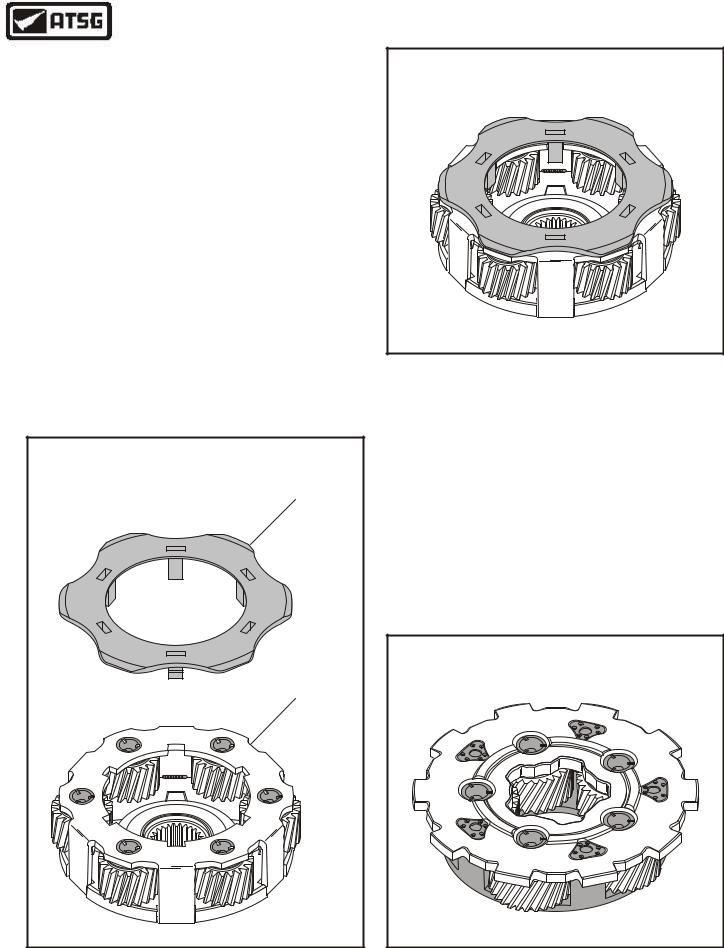
FRONT PLANETARY CARRIER ASSEMBLY
1.Inspect the front planetary carrier carefully for any wear and/or damage (See Figure 102).
2.Inspect the rear planetary carrier thrust bearing that is "Trapped" inside the planetary gears, for any wear and/or damage.
3.Inspect the front planetary carrier thrust washer for any wear and/or damage (See Figure 102).
4.Replace the thrust washer as necessary.
5.Install the front planetary carrier thrust washer by "Snapping" the tabs into place, as shown in Figure 102.
6.Set completed front planetary carrier assembly aside for the final assembly process. Refer to Figure 103.
FRONT PLANETARY
CARRIER THRUST WASHER
FRONT PLANETARY
CARRIER ASSEMBLY
Copyright © 2004 ATSG
Figure 102
COMPLETED FRONT PLANETARY
CARRIER ASSEMBLY
Copyright © 2004 ATSG
Figure 103
REAR PLANETARY CARRIER ASSEMBLY
1.Inspect the rear planetary carrier carefully for any wear and/or damage (See Figure 104).
2.Set completed rear planetary carrier assembly aside for the final assembly process. Refer to Figure 104.
COMPLETED REAR PLANETARY |
CARRIER ASSEMBLY |
Copyright © 2004 ATSG |
Figure 104
60 |
AUTOMATIC TRANSMISSION SERVICE GROUP |
|