


Chapter
4
Subsonic Airflow
Aerofoil Terminology . . . . . . . . . . |
. . . . |
. . |
. . |
. . |
. . |
. . . . |
. |
. |
52 |
Basics about Airflow . . . . . . . . . . |
. . . . |
. . |
. . |
. . |
. . |
. . . . |
. |
. |
54 |
Two Dimensional Airflow |
|
|
|
|
|
|
|
|
54 |
Summary |
|
|
|
|
|
|
|
|
62 |
Questions . . . . . . . . . . . . . . |
. . . . |
. . |
. . |
. . |
. . |
. . . . |
. |
. |
63 |
Answers . . . . . . . . . . . . . . |
. . . . . |
. . |
. . |
. . |
. . |
. . . . |
. |
|
.68 |
51
4 |
|
Subsonic Airflow |
|
||
|
|
|
|
|
MAXIMUM |
|
|
|
THICKNESS |
|
|
|
LOCATION OF |
|
|
|
MAX. THICKNESS |
|
|
LEADING |
MAXIMUM |
|
4 |
CAMBER |
|
|
EDGE |
|
||
|
|
|
|
Subsonic |
RADIUS |
MEAN CAMBER LINE |
|
|
|
||
|
|
|
|
Airflow |
|
CHORD LINE |
|
LEADING |
|
EDGE |
|
|
EDGE |
|
TRAILING |
|
|
CHORD |
|
|
|
LOCATION OF |
|
|
|
MAX. CAMBER |
|
|
|
|
TOTAL |
|
|
LIFT |
REACTION |
|
|
ANGLE OF |
|
|
|
ATTACK |
DRAG |
|
RELATIVE AIRFLOW |
||
|
|
||
|
|
AIRCRAFT FLIGHT PATH |
|
Figure 4.1
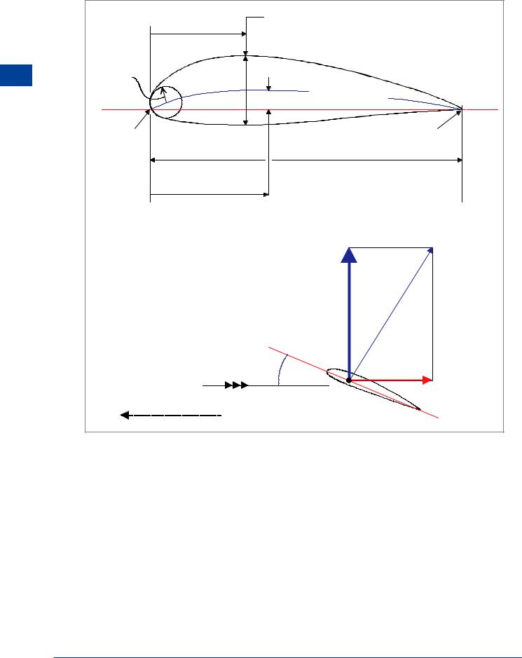
Aerofoil Terminology
Aerofoil
A shape capable of producing lift with relatively high efficiency.
Chord Line
A straight line joining the centres of curvature of the leading and trailing edges of an aerofoil.
Chord
The distance between the leading and trailing edges measured along the chord line.
Angle of Incidence
The angle between the wing root chord line and the longitudinal axis of the aircraft. (This angle is fixed for the wing, but may be variable for the tailplane).
52

Subsonic Airflow |
|
4 |
|
||
|
|
|
Mean Line or Camber Line
A line joining the leading and trailing edges of an aerofoil, equidistant from the upper and lower surfaces.
Maximum Camber
The maximum distance of the mean line from the chord line. Maximum camber is expressed as a percentage of the chord, with its location as a percentage of the chord aft of the leading edge. When the camber line lies above the chord line the aerofoil is said to have positive camber, and if the camber line is below the chord line, it is said to have negative camber. A symmetrical aerofoil has no camber because the chord line and camber line are coincidental.
Thickness/Chord Ratio
The maximum thickness or depth of an aerofoil section expressed as a percentage of the chord, with its location as a percentage of the chord aft of the leading edge. The thickness and thickness distribution of the aerofoil section have a great influence on its airflow characteristics.
Leading Edge Radius
The radius of curvature of the leading edge. The size of the leading edge radius can significantly affect the initial airflow characteristics of the aerofoil section.
Relative Airflow (RelativeWind or Free Stream Flow):
Relative Airflow has three qualities.
•DIRECTION - air parallel to and in the opposite direction to the flight path of the aircraft, in fact the path of the CG; the direction in which the aircraft is pointing is irrelevant.
•CONDITION - air close to, but unaffected by the presence of, the aircraft; its pressure, temperature and velocity are not affected by the passage of the aircraft through it.
•MAGNITUDE - The magnitude of the Relative Airflow is the TAS.
If Airflow does not possess all three of these qualities, it is referred to as EFFECTIVE AIRFLOW.
Total Reaction
The resultant of all the aerodynamic forces acting on the aerofoil section.
Centre of Pressure (CP)
The point on the chord line through which lift is considered to act.
Lift
The aerodynamic force which acts at 90° to the Relative Airflow.
Drag
The aerodynamic force which acts parallel to and in the same direction as the Relative Airflow (or opposite to the aircraft flight path).
Angle of Attack
(α or alpha) (can also be referred to as Aerodynamic Incidence). The angle between the chord line and the Relative Airflow.
The angle between the chord line and the effective airflow is referred to as the
EFFECTIVE ANGLE OF ATTACK.
Subsonic Airflow 4
53

4 |
|
Subsonic Airflow |
|
||
|
|
|
Airflow Subsonic 4
Basics about Airflow
When considering airflow velocity, it makes no difference to the pressure pattern if the aircraft is moving through the air or the air is flowing over the aircraft: it is the relative velocity which is the important factor. To promote a full understanding, references will be made to both wind tunnel experiments, where air is flowing over a stationary aircraft, and aircraft in flight moving through ‘stationary’ air.
Three dimensional airflow: Three dimensional flow is the true airflow over an aircraft and consists of a hypothetical two dimensional flow modified by various pressure differentials. Three dimensional airflow will be examined later.
Two dimensional airflow: Assumes a wing with the same aerofoil section along the entire span with no spanwise pressure differential or flow.
Two Dimensional Airflow
This CONCEPT, Figure 4.2 and Figure 4.3, is used to illustrate the basic principles of aerodynamic force generation.
As Airflows towards an aerofoil it will be turned towards the lower pressure at the upper surface; this is termed upwash. After passing over the aerofoil, the airflow returns to its original position and state; this is termed downwash.
Figure 4.2
INCREASED LOCAL |
|
VELOCITY |
DOWNWASH |
|
|
UPWASH |
|
Figure 4.3
54
Subsonic Airflow |
|
4 |
|
||
|
|
|
Influence of Dynamic Pressure
Figure 4.4 shows an aerofoil section at a representative angle of attack subject to a given dynamic pressure (IAS). “If the static pressure on one side of a body is reduced more than on the other side, a pressure differential will exist”.
Figure 4.5 shows the same aerofoil section at the same angle of attack, but subject to a higher dynamic pressure (IAS). “If the dynamic pressure (IAS) is increased, the pressure differential will increase”.
REPRESENTATIVE ANGLE OF ATTACK |
AND A GIVEN DYNAMIC PRESSURE |
(-) |
(+) |
(-) |
Subsonic Airflow 4
Figure 4.4
SAME ANGLE OF ATTACK |
INCREASED DYNAMIC PRESSURE |
(-) |
(+) |
(-) |
Figure 4.5
The pressure differential acting on the surface area will produce an upward acting force. “If the dynamic pressure (IAS) is increased, the upward force will increase”.
55
4 |
|
Subsonic Airflow |
|
||
|
|
|
Airflow Subsonic 4
Influence of Angle of Attack
At a constant dynamic pressure (IAS), increasing the angle of attack (up to about 16°) will likewise increase the pressure differential, but it will also change the pattern of pressure distribution.
The aerofoil profile presented to the airflow will determine the distribution of velocity and hence the distribution of pressure on the surface. This profile is determined by the aerofoil geometry, i.e. thickness and distribution (fixed), camber and distribution (assumed to be fixed for now) and by the angle of attack (variable).
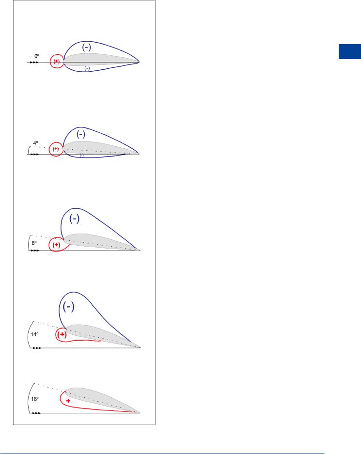
The greatest positive pressure occurs at the stagnation point where the relative flow velocity is zero. This stagnation point is located somewhere near the leading edge. As the angle of attack increases from -4°, the leading edge stagnation point moves from the upper surface around the leading edge to the lower surface. It is at the front stagnation point where the flow divides to pass over and under the section. The pressure at the stagnation point (stagnation pressure) is Static + Dynamic.
The flow over the top of the section accelerates rapidly around the nose and over the leading portion of the surface - inducing a substantial decrease in static pressure in those areas. The rate of acceleration increases with increase in angle of attack, up to about 16°. (Anything which changes the accurately manufactured profile of the leading portion of the surface can seriously disrupt airflow acceleration in this critical area e.g. ice, snow, frost, dirt or dents). The pressure reduces continuously from the stagnation value through the free stream value to a position on the top surface where a peak negative value is reached. From there onwards the flow continuously slows down again and the pressure increases back to the free stream value in the region of the trailing edge.
At angles of attack less than 8° the flow under the section is accelerated much less, reducing the pressure to a small negative value, also with subsequent deceleration and increase in pressure back to the free stream value in the region of the trailing edge.
The pressure differential between the leading edge stagnation point and the lower pressure at the trailing edge creates a force acting backward which is called ‘form (pressure) drag’. (This will be discussed in more detail later).
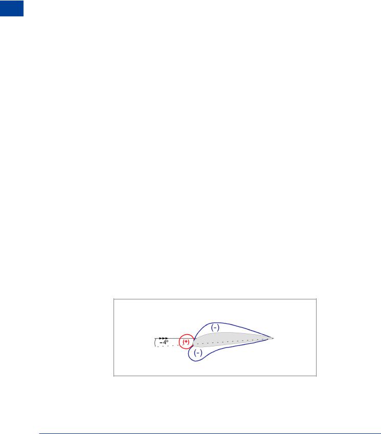
Angle of Attack (-4°)
The decrease in pressure above and below the section are equal and no differential exists. There will, thus, be no lift force. (Figure 4.6). This can be called the “zero lift angle of attack”.
Figure 4.6
56
Subsonic Airflow |
|
4 |
|
||
|
|
|
Angles of Attack (0° to 8°)
Compared to free stream static pressure, there is a pressure decrease over the upper surface and a lesser decrease over most of the lower surface. For a cambered aerofoil there will be a small amount of lift even at small negative angles (-4° to 0°).
Angles of attack (0° to 16°)
Increasing the angle of attack increases the lift force because the acceleration of the airflow over the top surface is increased by the reduction in effective cross-sectional area of the local streamtube.
The reduced pressure ‘peak’ moves forward as the angle of attack increases.
The greatest contribution to overall lift comes from the upper surface.
Pressure Gradient
This is a change in air pressure over distance. The greater the difference in pressure between two points, the steeper the gradient. A favourable gradient is when air pressure is falling in the direction of airflow. An adverse pressure gradient is when air pressure is rising in the direction of airflow, such as between the point of minimum pressure on the top surface and the trailing edge. The higher the angle of attack, the steeper the pressure gradient. At angles of attack higher than approximately 16°, the extremely steep adverse pressure gradient prevents air that is flowing over the top surface from following the aerofoil contour, and the previously smooth streamline flow will separate from the surface, causing the low pressure area on the top of the section to suddenly collapse. Any pressure differential remaining is due to the pressure increase on the lower surface only. This condition is known as the stall and will be described in detail in Chapter 7.
Subsonic Airflow 4
Figure 4.7
57

4 Subsonic Airflow
Centre of Pressure (CP)
The whole surface of the aerofoil contributes to lift, but the point along the chord where the distributed lift is effectively concentrated is termed the Centre of Pressure (Figure 4.8). The location of the CP is a function of camber and section lift coefficient, i.e. angle of attack.
Airflow Subsonic 4
Figure 4.8
Movement of the Centre of Pressure
As the angle of attack increases from 0° to 16° the upper ‘suction’ peak moves forward (Figure 4.7), so the point at which the lift is effectively concentrated, the CP, will move forward. The CP moves forward and the magnitude of the lift force increases with increase in angle of attack until the stall is reached when the lift force decreases abruptly and the CP generally moves back along the chord (Figure 4.9). Note that the CP is at its most forward location just before the stall (CL MAX).
Aerodynamic Force Coefficient
A coefficient is a dimensionless number expressing degree of magnitude. An aerodynamic force coefficient is a common denominator for all A/C of whatever weight, size and speed. An aerodynamic force coefficient is a dimensionless ratio between the average aerodynamic pressure and the airstream dynamic pressure.
By this definition a lift coefficient (CL ) is the ratio between lift divided by the wing planform area and dynamic pressure and a drag coefficient (CD) is the ratio between drag divided by the wing planform area and dynamic pressure.
The use of the coefficient of an aerodynamic force is necessary since the force coefficient is:
•An index of the aerodynamic force independent of area, density and velocity. It is derived from the relative pressure and velocity distribution.
•Influenced only by the shape of the surface and angle of attack since these factors determine the pressure distribution.
58

Subsonic Airflow |
|
4 |
|
||
|
|
|
ATTACK |
CL MAX |
|
|
|
|
|
|
|
|
|
|
|
|
|
|
|
|
|
|
4 |
|
ANGLE OF |
|
|
|
|
|
|
|
|
|
Subsonic Airflow |
0 |
10% |
20% |
30% |
40% |
50% |
60% |
70% |
80% |
90% |
100% |
|
|
|
|
|
CP POSITION |
|
|
|
|
|
|
|
|
(Percentage chord, aft of |
leading |
edge) |
|
|
|
||
LEADING |
|
|
|
|
|
|
|
|
|
TRAILING |
EDGE |
|
|
|
|
|
|
|
|
|
EDGE |
Figure 4.9 CP movement with angle of attack
59

4 |
|
Subsonic Airflow |
|
||
|
|
|
Airflow Subsonic 4
Development of Aerodynamic Pitching Moments
The distribution of pressure over a surface is the source of aerodynamic moments as well as forces. There are two ways to consider the effects of changing angle of attack on the pitching moment of an aerofoil.
• Changes in the magnitude of lift acting through a moving CP, or more simply:
•Changes in the magnitude of lift always acting through an Aerodynamic Centre, which is fixed.
Aerodynamic Centre (AC)
The AC is a ‘fixed’ point on the chord line and is defined as: ‘The point where all changes in the magnitude of the lift force effectively take place’, AND: ‘The point about which the pitching moment will remain constant at ‘normal’ angles of attack’. A nose-down pitching moment exists about the AC which is the product of a force (lift at the CP) and an arm (distance from the CP to the AC). Since an increase in angle of attack will increase the lift force, but also move the CP towards the AC (shortening the lever arm), the moment about the AC remains the same at any angle of attack within the “normal” range.
|
|
L 1 |
|
1 |
M |
|
|
|
AC |
CP |
L 2 |
|
|
|
|
|
|
d1 |
|
|
|
2 |
|
|
|
M |
|
|
|
AC |
CP |
|
|
d2 |
|
Figure 4.10
When considering subsonic airflows of less than M 0.4, the AC is located at the 25% chord point for any aerofoil regardless of camber, thickness and angle of attack.
The aerodynamic centre (AC) is an aerodynamic reference point, the most direct application being to the longitudinal stability of an aircraft, which will be discussed in Chapter 10.
60

Subsonic Airflow |
|
4 |
|
||
|
|
|
Pitching Moment for a Symmetrical Aerofoil
Note the change in pressure distribution with angle of attack for the symmetrical aerofoil in Figure 4.11. When at zero angle of attack, the upper and lower surface forces are equal and located at the same point. With an increase in angle of attack, the upper surface force increases while the lower surface force decreases. A change in the magnitude of lift has taken place with no change in the CP position - a characteristic of symmetrical aerofoils. Thus, the pitching moment about the AC for a symmetrical aerofoil will be zero at ‘normal’ angles of attack - one of the big advantages of symmetrical aerofoils.
SYMMETRICAL AEROFOIL
AT ZERO LIFT
 AC
AC
SYMMETRICAL AEROFOIL
AT POSITIVE LIFT
 AC
AC
Subsonic Airflow 4
Figure 4.11
61