

- •Textbook Series
- •Contents
- •1 Overview and Definitions
- •Overview
- •General Definitions
- •Glossary
- •List of Symbols
- •Greek Symbols
- •Others
- •Self-assessment Questions
- •Answers
- •2 The Atmosphere
- •Introduction
- •The Physical Properties of Air
- •Static Pressure
- •Temperature
- •Air Density
- •International Standard Atmosphere (ISA)
- •Dynamic Pressure
- •Key Facts
- •Measuring Dynamic Pressure
- •Relationships between Airspeeds
- •Airspeed
- •Errors and Corrections
- •V Speeds
- •Summary
- •Questions
- •Answers
- •3 Basic Aerodynamic Theory
- •The Principle of Continuity
- •Bernoulli’s Theorem
- •Streamlines and the Streamtube
- •Summary
- •Questions
- •Answers
- •4 Subsonic Airflow
- •Aerofoil Terminology
- •Basics about Airflow
- •Two Dimensional Airflow
- •Summary
- •Questions
- •Answers
- •5 Lift
- •Aerodynamic Force Coefficient
- •The Basic Lift Equation
- •Review:
- •The Lift Curve
- •Interpretation of the Lift Curve
- •Density Altitude
- •Aerofoil Section Lift Characteristics
- •Introduction to Drag Characteristics
- •Lift/Drag Ratio
- •Effect of Aircraft Weight on Minimum Flight Speed
- •Condition of the Surface
- •Flight at High Lift Conditions
- •Three Dimensional Airflow
- •Wing Terminology
- •Wing Tip Vortices
- •Wake Turbulence: (Ref: AIC P 072/2010)
- •Ground Effect
- •Conclusion
- •Summary
- •Answers from page 77
- •Answers from page 78
- •Questions
- •Answers
- •6 Drag
- •Introduction
- •Parasite Drag
- •Induced Drag
- •Methods of Reducing Induced Drag
- •Effect of Lift on Parasite Drag
- •Aeroplane Total Drag
- •The Effect of Aircraft Gross Weight on Total Drag
- •The Effect of Altitude on Total Drag
- •The Effect of Configuration on Total Drag
- •Speed Stability
- •Power Required (Introduction)
- •Summary
- •Questions
- •Annex C
- •Answers
- •7 Stalling
- •Introduction
- •Cause of the Stall
- •The Lift Curve
- •Stall Recovery
- •Aircraft Behaviour Close to the Stall
- •Use of Flight Controls Close to the Stall
- •Stall Recognition
- •Stall Speed
- •Stall Warning
- •Artificial Stall Warning Devices
- •Basic Stall Requirements (EASA and FAR)
- •Wing Design Characteristics
- •The Effect of Aerofoil Section
- •The Effect of Wing Planform
- •Key Facts 1
- •Super Stall (Deep Stall)
- •Factors that Affect Stall Speed
- •1g Stall Speed
- •Effect of Weight Change on Stall Speed
- •Composition and Resolution of Forces
- •Using Trigonometry to Resolve Forces
- •Lift Increase in a Level Turn
- •Effect of Load Factor on Stall Speed
- •Effect of High Lift Devices on Stall Speed
- •Effect of CG Position on Stall Speed
- •Effect of Landing Gear on the Stall Speed
- •Effect of Engine Power on Stall Speed
- •Effect of Mach Number (Compressibility) on Stall Speed
- •Effect of Wing Contamination on Stall Speed
- •Warning to the Pilot of Icing-induced Stalls
- •Stabilizer Stall Due to Ice
- •Effect of Heavy Rain on Stall Speed
- •Stall and Recovery Characteristics of Canards
- •Spinning
- •Primary Causes of a Spin
- •Phases of a Spin
- •The Effect of Mass and Balance on Spins
- •Spin Recovery
- •Special Phenomena of Stall
- •High Speed Buffet (Shock Stall)
- •Answers to Questions on Page 173
- •Key Facts 2
- •Questions
- •Key Facts 1 (Completed)
- •Key Facts 2 (Completed)
- •Answers
- •8 High Lift Devices
- •Purpose of High Lift Devices
- •Take-off and Landing Speeds
- •Augmentation
- •Flaps
- •Trailing Edge Flaps
- •Plain Flap
- •Split Flap
- •Slotted and Multiple Slotted Flaps
- •The Fowler Flap
- •Comparison of Trailing Edge Flaps
- •and Stalling Angle
- •Drag
- •Lift / Drag Ratio
- •Pitching Moment
- •Centre of Pressure Movement
- •Change of Downwash
- •Overall Pitch Change
- •Aircraft Attitude with Flaps Lowered
- •Leading Edge High Lift Devices
- •Leading Edge Flaps
- •Effect of Leading Edge Flaps on Lift
- •Leading Edge Slots
- •Leading Edge Slat
- •Automatic Slots
- •Disadvantages of the Slot
- •Drag and Pitching Moment of Leading Edge Devices
- •Trailing Edge Plus Leading Edge Devices
- •Sequence of Operation
- •Asymmetry of High Lift Devices
- •Flap Load Relief System
- •Choice of Flap Setting for Take-off, Climb and Landing
- •Management of High Lift Devices
- •Flap Extension Prior to Landing
- •Questions
- •Annexes
- •Answers
- •9 Airframe Contamination
- •Introduction
- •Types of Contamination
- •Effect of Frost and Ice on the Aircraft
- •Effect on Instruments
- •Effect on Controls
- •Water Contamination
- •Airframe Aging
- •Questions
- •Answers
- •10 Stability and Control
- •Introduction
- •Static Stability
- •Aeroplane Reference Axes
- •Static Longitudinal Stability
- •Neutral Point
- •Static Margin
- •Trim and Controllability
- •Key Facts 1
- •Graphic Presentation of Static Longitudinal Stability
- •Contribution of the Component Surfaces
- •Power-off Stability
- •Effect of CG Position
- •Power Effects
- •High Lift Devices
- •Control Force Stability
- •Manoeuvre Stability
- •Stick Force Per ‘g’
- •Tailoring Control Forces
- •Longitudinal Control
- •Manoeuvring Control Requirement
- •Take-off Control Requirement
- •Landing Control Requirement
- •Dynamic Stability
- •Longitudinal Dynamic Stability
- •Long Period Oscillation (Phugoid)
- •Short Period Oscillation
- •Directional Stability and Control
- •Sideslip Angle
- •Static Directional Stability
- •Contribution of the Aeroplane Components.
- •Lateral Stability and Control
- •Static Lateral Stability
- •Contribution of the Aeroplane Components
- •Lateral Dynamic Effects
- •Spiral Divergence
- •Dutch Roll
- •Pilot Induced Oscillation (PIO)
- •High Mach Numbers
- •Mach Trim
- •Key Facts 2
- •Summary
- •Questions
- •Key Facts 1 (Completed)
- •Key Facts 2 (Completed)
- •Answers
- •11 Controls
- •Introduction
- •Hinge Moments
- •Control Balancing
- •Mass Balance
- •Longitudinal Control
- •Lateral Control
- •Speed Brakes
- •Directional Control
- •Secondary Effects of Controls
- •Trimming
- •Questions
- •Answers
- •12 Flight Mechanics
- •Introduction
- •Straight Horizontal Steady Flight
- •Tailplane and Elevator
- •Balance of Forces
- •Straight Steady Climb
- •Climb Angle
- •Effect of Weight, Altitude and Temperature.
- •Power-on Descent
- •Emergency Descent
- •Glide
- •Rate of Descent in the Glide
- •Turning
- •Flight with Asymmetric Thrust
- •Summary of Minimum Control Speeds
- •Questions
- •Answers
- •13 High Speed Flight
- •Introduction
- •Speed of Sound
- •Mach Number
- •Effect on Mach Number of Climbing at a Constant IAS
- •Variation of TAS with Altitude at a Constant Mach Number
- •Influence of Temperature on Mach Number at a Constant Flight Level and IAS
- •Subdivisions of Aerodynamic Flow
- •Propagation of Pressure Waves
- •Normal Shock Waves
- •Critical Mach Number
- •Pressure Distribution at Transonic Mach Numbers
- •Properties of a Normal Shock Wave
- •Oblique Shock Waves
- •Effects of Shock Wave Formation
- •Buffet
- •Factors Which Affect the Buffet Boundaries
- •The Buffet Margin
- •Use of the Buffet Onset Chart
- •Delaying or Reducing the Effects of Compressibility
- •Aerodynamic Heating
- •Mach Angle
- •Mach Cone
- •Area (Zone) of Influence
- •Bow Wave
- •Expansion Waves
- •Sonic Bang
- •Methods of Improving Control at Transonic Speeds
- •Questions
- •Answers
- •14 Limitations
- •Operating Limit Speeds
- •Loads and Safety Factors
- •Loads on the Structure
- •Load Factor
- •Boundary
- •Design Manoeuvring Speed, V
- •Effect of Altitude on V
- •Effect of Aircraft Weight on V
- •Design Cruising Speed V
- •Design Dive Speed V
- •Negative Load Factors
- •The Negative Stall
- •Manoeuvre Boundaries
- •Operational Speed Limits
- •Gust Loads
- •Effect of a Vertical Gust on the Load Factor
- •Effect of the Gust on Stalling
- •Operational Rough-air Speed (V
- •Landing Gear Speed Limitations
- •Flap Speed Limit
- •Aeroelasticity (Aeroelastic Coupling)
- •Flutter
- •Control Surface Flutter
- •Aileron Reversal
- •Questions
- •Answers
- •15 Windshear
- •Introduction (Ref: AIC 84/2008)
- •Microburst
- •Windshear Encounter during Approach
- •Effects of Windshear
- •“Typical” Recovery from Windshear
- •Windshear Reporting
- •Visual Clues
- •Conclusions
- •Questions
- •Answers
- •16 Propellers
- •Introduction
- •Definitions
- •Aerodynamic Forces on the Propeller
- •Thrust
- •Centrifugal Twisting Moment (CTM)
- •Propeller Efficiency
- •Variable Pitch Propellers
- •Power Absorption
- •Moments and Forces Generated by a Propeller
- •Effect of Atmospheric Conditions
- •Questions
- •Answers
- •17 Revision Questions
- •Questions
- •Answers
- •Explanations to Specimen Questions
- •Specimen Examination Paper
- •Answers to Specimen Exam Paper
- •Explanations to Specimen Exam Paper
- •18 Index

High Speed Flight 13
Figure 13.41 shows a series of expansion waves in a supersonic airflow. After passing through the bow shock wave, the compressed supersonic flow is free to expand and follow the surface contour. As there are no sudden changes to the airflow, the expansion waves are NOT shock waves. A supersonic airflow passing through an expansion wave will experience the following changes:-
•The airflow is accelerated; the velocity and Mach number behind the expansion wave are greater.
•The flow direction is changed to follow the surface.
•The static pressure of the airflow behind the expansion wave is decreased.
•The density of the airflow behind the expansion wave is decreased.
•Since the flow change is gradual there is no “shock” and no loss of energy in the airflow. An expansion wave does not dissipate airflow energy.
Sonic Bang
The intensity of shock waves reduces with distance from the aircraft, but the pressure waves can be of sufficient magnitude to create a disturbance on the ground. Thus, “sonic bangs” are a consequence of supersonic flight. The pressure waves move with aircraft ground speed over the earth surface.
Methods of Improving Control at Transonic Speeds
It has been seen that control effectiveness may decrease in the transonic region if conventional control surfaces are used. Some improvement in control effectiveness may be obtained by placing vortex generators ahead of control surfaces.
However, alternative forms of control such as:
•an all moving (slab) tailplane
•roll control spoilers give better control in the transonic speed region.
These types of control are explained in Flying Controls Chapter 11. Control surface buzz is sometimes remedied by fitting narrow strips along the trailing edge of the control surface, or it may be prevented by including dampers in the control system or by increasing the stiffness of the control circuit.
Because of the high control loads involved at high speeds and the variation in loads through the transonic region, the controls will normally be fully power operated with artificial feel.
High Speed Flight 13
447

13 High Speed Flight
Flight Speed High 13
The table in Figure 13.42 is provided to summarize the characteristics of the three principal wave forms encountered with supersonic flow.
Supersonic Wave Characteristics
TYPE OF WAVE |
OBLIQUE Shock wave |
NORMAL Shock wave |
|
|
EXPANSION wave |
|||||
|
|
|
|
|
|
|
|
|
|
|
|
|
|
|
|
|
|
|
|
|
|
|
|
|
|
|
|
|
|
|
|
|
|
|
|
|
|
|
|
|
|
|
|
|
|
|
|
|
|
|
|
|
|
|
|
DEFINITION |
A PLANE OF DISCONTINUITY, |
A PLANE OF DISCONTINUITY, |
|
|
|
|
INCLINED MORE THAN 90º |
NORMAL TO FLOW DIRECTION |
|
|
|
|
FROM FLOW DIRECTION |
|
|
|
|
|
|
|
|
|
|
FLOW DIRECTION |
TURNED INTO A PRECEDING |
NO CHANGE |
TURNED AWAY FROM |
|
|
CHANGE |
FLOW |
|
PRECEDING FLOW |
|
|
|
|
|
|
|
|
EFFECT ON VELOCITY |
DECREASED BUT STILL |
DECREASED TO SUBSONIC |
INCREASED TO HIGHER |
|
|
and MACH NUMBER. |
SUPERSONIC |
|
SUPERSONIC |
|
|
BEHIND WAVE |
|
|
|
|
|
|
|
|
|
|
|
EFFECT ON STATIC |
INCREASE |
GREAT INCREASE |
DECREASE |
|
|
PRESSURE and DENSITY |
|
|
|
|
|
|
|
|
|
|
|
EFFECT ON ENERGY |
DECREASE |
GREAT DECREASE |
NO CHANGE ( NO SHOCK ) |
|
|
OF AIRFLOW |
|
|
|
|
|
|
|
|
|
|
|
EFFECT ON |
INCREASE |
INCREASE |
DECREASE |
|
|
TEMPERATURE |
|
|
|
|
|
|
|
|
|
|
|
|
Figure 13.42 Characteristics of the three principle wave forms |
|
|
|
448
High Speed Flight
Sweepback - Fact Sheet
Sweep Angle: The angle between the line of 25% chords and a perpendicular to the root chord.
Purpose of Sweepback: To increase MCRIT.
A Swept Wing Increases the Critical Mach Number (MCRIT).
All other effects from a swept wing are by-products, most of them disadvantages. However, the benefits from a higher MCRIT outweigh the associated disadvantages.
By-products of Sweepback
1.Increased tendency to stall at the tip first - minimized by fitting wing fences, vortilons or saw tooth leading edges.
•Tip stall can lead to pitch-up, a major disadvantage.
•Pitch-up can give the tendency for a swept wing aircraft to Super Stall.
•Aircraft that show a significant tendency to pitch-up at the stall MUST be fitted with a stall prevention device; a stick pusher.
Close to the stall, ailerons and coordinated use of rudder should be used to maintain wings level because the use of rudder alone would give excessive rolling moments. (VSR is adjusted so that adequate roll control exists from the use of ailerons close to the stall).
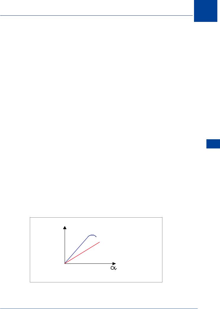
2.When compared to a straight wing of the same section, a swept wing is less aerodynamically efficient.
•At a given angle of attack CL is less.
•CLMAX is less and occurs at a higher angle of attack.
•The lift curve has a smaller gradient (change in CL per degree change in alpha is less).
13
High Speed Flight 13
C L |
HIGH ASPECT |
RATIO |
 LOW ASPECT RATIO
(or sweepback)
Figure 13.43
449

13 High Speed Flight
• Swept wings must be fitted with complex high lift devices, both leading and trailing
|
edge, to give a reasonable take-off and landing distance. |
||
|
◦◦ |
The least efficient type of leading edge device is used on the inboard part of the |
|
|
|
swept wing to help promote root stall. |
|
|
• Because of the higher stalling angle of attack, the fin or vertical stabilizer is swept to |
||
|
delay fin stall to a greater sideslip angle. |
||
|
• A swept wing must be flown at a higher angle of attack than a straight wing to give the |
||
|
required lift coefficient; this is most noticeable at low speeds. |
||
|
• One of the few advantages of a swept wing is that it is less sensitive to changes in angle |
||
|
of attack due to gust or turbulence; a smaller change in Load Factor for a given gust will |
||
|
result. |
||
|
3. |
A swept wing makes a small positive contribution to static directional stability. |
|
|
4. |
A swept wing makes a significant positive contribution to static lateral stability. |
|
|
5. |
At speeds in excess of MCRIT a swept wing generates a nose-down pitching moment; |
|
13 |
|
a phenomena known as Mach Tuck, High Speed Tuck or Tuck Under. This must be |
|
|
counteracted by a Mach Trim System which adjusts the aircraft’s longitudinal trim. |
||
High |
|
||
6. |
The hinge line of trailing edge ‘flap’ type control surfaces are not at right angles to the |
||
FlightSpeed |
|||
|
airflow, which reduces the efficiency of the controls. |
||
|
|
||
450