


7 Stalling
Stalling 7
Effect of CG Position on Stall Speed
CS-25.103(b) states that VCLMAX is determined with the CG position that results in the highest value of reference stall speed.
L
 CP
CP
TAIL
DOWNLOAD
W
Figure 7.24
If the CG is in front of the CP, Figure 7.24, giving a nose-down pitching moment and there is no thrust/drag moment to oppose it, the tailplane must provide a down load to maintain equilibrium. Lift must be increased to maintain an upwards force equal to the increased
downwards force. From the 1g stall formula it can be seen that CLMAX will be divisible into the increased lift force more times.
|
|
√ |
|
|
|
VS1g |
= |
|
L |
|
|
|
|
|
|||
|
|
½ ρ CLMAX |
S |
||
|
|
|
|
Forward movement of the CG increases stall speed.
174
Stalling 7
Effect of Landing Gear on the Stall Speed
L
 CP
CP
TAIL
DOWNLOAD
PROFILE DRAG
FROM GEAR
W
Figure 7.25
From Figure 7.25 it can be seen that with the undercarriage down, profile drag below the CG is increased. This will give a nose-down pitching moment which must be balanced by increasing the tail down load. Lift must be increased to balance the increased downwards force.
CG movement due to the direction in which the undercarriage extends will have an insignificant influence on stall speed. By far the greater influence is the increased profile drag of the gear when it is extended.
Extending the undercarriage increases stall speed.
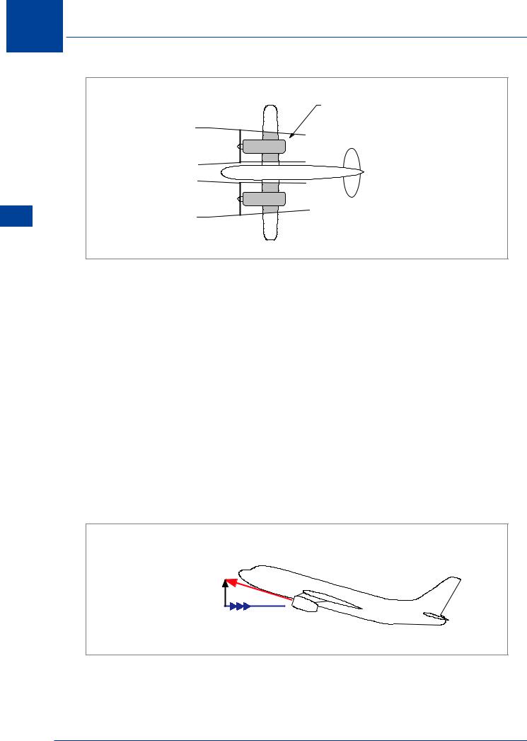
Effect of Engine Power on Stall Speed
CS-25.103(b) states that VCLMAX is determined with zero thrust at the stall speed.
When establishing VCLMAX the engines must be at zero thrust and it is assumed that the weight of the aircraft is entirely supported by lift. If thrust is applied close to the stall, the nose high
attitude of the aircraft produces a vertical component of thrust, Figure 7.27, which assists in supporting the weight and less lift is required. Aircraft with propellers will have an additional effect caused by the propeller slipstream.
The most important factors affecting this relationship are engine type (propeller or jet), thrust to weight ratio and inclination of the thrust vector at CLMAX.
Stalling 7
175
7 Stalling
INDUCED FLOW
FROM PROPELLER
SLIPSTREAM
Stalling 7
Figure 7.26
Propeller
Figure 7.26. The slipstream velocity behind the propeller is greater than the free stream flow, depending on the thrust developed. Thus, when the propeller aeroplane is at low airspeeds and high power, the dynamic pressure within the propeller slipstream is much greater than that outside and this generates much more lift than at zero thrust. The lift of the aeroplane at a given angle of attack and airspeed will be greatly affected. If the aircraft is in the landing flare, reducing power suddenly will cause a significant reduction in lift and a heavy landing could result. On the other hand, a potentially heavy landing can be avoided by a judicious ‘blast’ from the engines.
Jet
The typical jet aircraft does not experience the induced flow velocities encountered in propeller driven aeroplanes, thus the only significant factor is the vertical component of thrust, Figure 7.27. Since this vertical component contributes to supporting the weight of the aircraft, less aerodynamic lift is required to hold the aeroplane in flight. If the thrust is large and is given a large inclination at maximum lift angle, the effect on stall speed can be very large. Since there is very little induced flow from the jet, the angle of attack at stall is essentially the same poweron as power-off.
VERTICAL
COMPONENT 
OF THRUST
Figure 7.27
Power-on stall speed is less than power-off. This will be shown to be significant during the study of windshear in Chapter 15.
176

Stalling 7
Effect of Mach Number (Compressibility) on Stall Speed
As an aircraft flies faster, the streamline pattern around the wing changes. Faster than about four tenths the speed of sound (M 0.4) these changes start to become significant. This phenomena is known as compressibility. This will be discussed fully in Chapter 13.
Pressure waves, generated by the passage of a wing through the air, propagate ahead of the wing at the speed of sound. These pressure waves upwash air ahead of the wing towards the lower pressure on the top surface.
Stalling 7
HIGH SPEED
LOW SPEED
Figure 7.28
Figure 7.28 shows that at low speed, the streamline pattern is affected far ahead of the wing and the air has a certain distance in which to upwash. As speed increases, the wing gets closer to its leading pressure wave, and the streamline pattern is affected a shorter distance ahead so must approach the wing at a steeper angle.
This change in the streamline pattern accentuates the adverse pressure gradient near the leading edge and flow separation occurs at a reduced angle of attack. Above M0.4 CLMAX decreases as shown in Figure 7.29.
CLMAX |
|
|
0 4 |
1 0 |
M |
|
|
|
|
Figure 7.29 |
|
177

7 Stalling
Stalling 7
Referring to the 1g stall speed formula:
|
|
√ |
|
|
|
VS1g |
= |
|
|
L |
|
|
|
|
|||
|
|
½ |
ρ CLMAX S |
||
|
|
|
|
||
If CLMAX decreases, VS1g will increase. |
|
|
|
|
|
To maintain a constant EAS as altitude increases, TAS is increased. Also, outside air temperature decreases with increasing altitude, causing the local speed of sound to decrease. Mach number is proportional to TAS and inversely proportional to the local speed of sound (a):
TAS
M = a
Therefore, at a constant EAS, Mach number will increase as altitude increases.
Alt 
 1g Stall Speed
EAS
Figure 7.30
Figure 7.30 shows the variation of stalling speed with altitude at constant load factor (n). Such a curve is called the stalling boundary for the given load factor, in which altitude is plotted against equivalent airspeed. At this load factor (1g), the aircraft cannot fly at speeds to the left of this boundary. It is clear that over the lower range of altitude, stall speed does not vary with altitude. This is because at these low altitudes, the Mach number at VS is less than M 0.4, too low for compressibility effects to be present. Eventually (approximately 30 000 ft), Mach number at VS has increased with altitude to such an extent that these effects are important, and the rise in stalling speed with altitude is apparent.
Using the example aeroplane from earlier, the VS1g of 150 kt is equal to M 0.4 at approximately 29 000 ft using ISA values.
As altitude increases, stall speed is initially constant then increases, due to compressibility.
178