

Lift 5
Three Dimensional Airflow
So far we have considered only two dimensional airflow. This has been a foundation for an appreciation of the actual pattern of airflow over an aircraft. Even minute pressure differences will modify airflow direction by inducing air to flow towards any region of lower pressure. Three dimensional airflow modifies the effective angle of attack, increases drag, alters stalling characteristics and can influence the control and stability of the aircraft. From now on, instead of just an aerofoil section, the entire wing will be considered.
Wing Terminology
Wing Area (S): The plan surface area of the wing. Although a portion of the area may be covered by fuselage or engine nacelles, the pressure carryover on these surfaces allows legitimate consideration of the entire plan area.
Wingspan (b): The distance from tip to tip.
Average Chord (c): The mean geometric chord. The product of the span and the average chord is the wing area (b × c = S).
Aspect Ratio (AR): The proportion of the span and the average chord (AR = b/c). If the planform has curvature and the average chord is not easily determined, an alternative expression is b2/S. The aspect ratio of the wing determines the aerodynamic characteristics and structural weight. Typical aspect ratios vary from 35 for a high performance sailplane to 3 for a jet fighter. The aspect ratio of a modern high speed jet transport is about 12.
Root Chord (CR): The chord length at the wing centre line.
Tip Chord (CT): The chord length at the wing tip.
Taper Ratio (CT / CR): The ratio of the tip chord to the root chord. The taper ratio affects the lift distribution and the structural weight of the wing. A rectangular wing has a taper ratio of 1.0 while the pointed tip delta wing has a taper ratio of 0.0
SweepAngle: Usuallymeasuredastheanglebetweenthelineof25%chordsandaperpendicular to the root chord. The sweep of a wing causes definite changes in compressibility, maximum lift, and stall characteristics.
Mean Aerodynamic Chord (MAC): A rectangular wing of this chord and the same span would have broadly similar pitching moment characteristics. The MAC is located on the reference axis of the aircraft and is a primary reference for longitudinal stability considerations.
Lift 5
85
5 Lift
Wing Tip Vortices
Lift 5
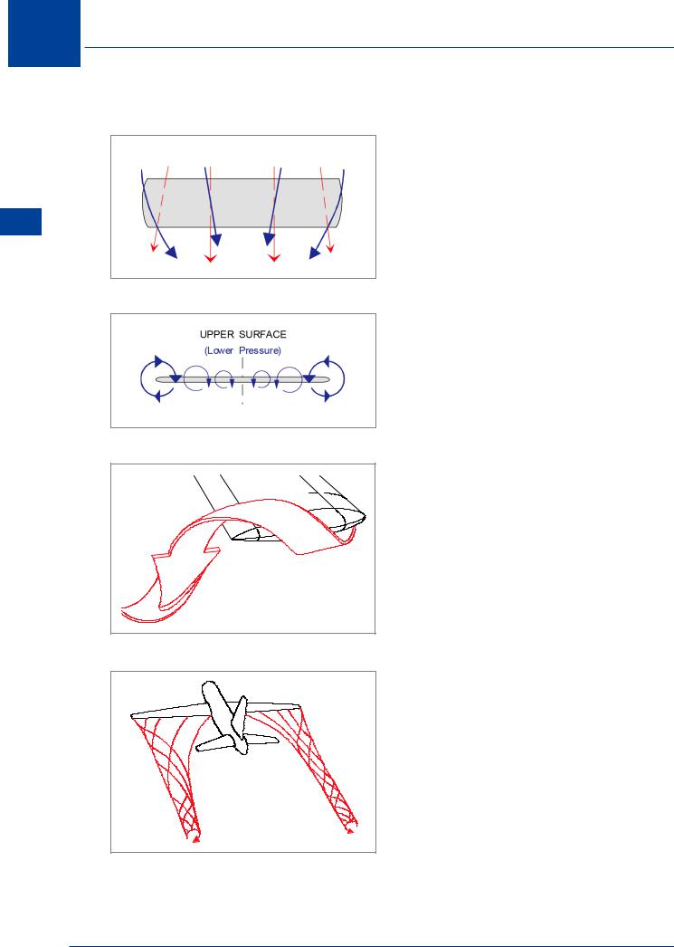
Figure 5.11
Figure 5.12
Figure 5.13
Air flowing over the top surface of a wing is at a lower pressure than that beneath. The trailing edge and the wing tips are where the airflows interact. The pressure differential modifies the directions of flow, inducing a span wise vector towards the root on the upper surface and, generally, towards the tip on the lower surface, Figure 5.11. “Conventionally”, an aircraft is viewed from the rear. An anticlockwise vortex will be induced at the right wing tip and a clock-wise vortex at the left wing tip, Figure 5.12, Figure 5.13 & Figure 5.14.
At higher angles of attack (lower IAS) the decreased chordwise vector will increase the effect of the resultant spanwise flow, making the vortices stronger.
Induced Downwash
(Figure 5.15) Trailing vortices create certain vertical velocity components in the airflow in the vicinity of the wing, both in front of and behind it. These vertical velocities cause a downwash over the wing resulting in a reduction in the effective angle of attack. The stronger the vortices, the greater the reduction in effective angle of attack. Because of this local reduction in effective angle of attack, the overall lift generated by a wing will be below the value that would be generated if there were no spanwise pressure differential. It is the production of lift itself which reduces the magnitude of the lift force being generated. To replace the lift lost by the increased downwash, the aircraft must be flown at a higher angle of attack. This increases drag. This extra drag is called induced drag. The stronger the vortices, the greater the induced drag.
Figure 5.14
86

Lift 5
Upwash Increased
Vertical |
Velocities |
|
in the |
vicinity of |
Downwash Increased |
the wing are a function of |
||
tip vortex strength
Lift 5
EFFECTIVE AIRFLOW
Angular deflection of effective airflow
is a function of both vortex strength and True Airspeed (TAS).
V |
|
|
|
|
|
Relative |
Airflow |
|
|
Induced |
|
|
|
|
|
V |
Downwash |
|
|
|
|
|
|
|
|
|
|
Induced |
Drag (D i) |
|
|
Lift |
With |
|
|
|
|
Normal Downwash |
Lift Inclined Rearwards because of |
||
|
|
|
|
||
|
|
|
|
Decreased Effective Angle of Attack |
|
Effective |
|
|
|
i |
|
|
|
|
|
|
|
Airflow |
|
|
e |
|
|
|
|
|
|
|
|
|
|
|
i |
|
|
Relative |
Airflow |
|
|
|
|
 e = effective angle of attack
  i = induced angle of attack
Figure 5.15
Wing tip vortices, in particular their influence on upwash and downwash, have a significant effect on several important areas of aircraft aerodynamics, stability and control. Some of these effects will be examined now and throughout the remaining chapters.
87

5 Lift
Lift 5
Wake Turbulence: (Ref: AIC P 072/2010)
Trailing wing tip vortices extend behind aircraft for a considerable distance and can present an extreme hazard to any aircraft unfortunate enough to encounter them. Maximum tangential airspeed in the vortex system may be as high as 90 m/s (300 ft/sec) immediately behind a large aircraft. Wake turbulence cannot be detected, so it is important for pilots to be aware of the potential distribution and duration of trailing vortices, plus modifications made to the “classic” vortex system by surface wind speed and direction.
AircraftWakeVortex Characteristics
Wake vortex generation begins when the nose wheel lifts off the runway on take-off and continues until the nose wheel touches down on landing. Wake vortices exist behind every aircraft, including helicopters, when in flight, but are most severe when generated by heavy aircraft. They present the greatest danger during the take-off, initial climb, final approach and landing phases of flight - in other words, at low altitude where large numbers of aircraft congregate. A wake turbulence encounter is a hazard due to potential loss of control and possible structural damage, and if the experience takes place near the ground, there may be insufficient time and/or altitude to recover from an upset.
Figure 5.16
The characteristics of trailing vortices are determined by the “generating” aircraft’s:
•Gross weight - the higher the weight, the stronger the vortices.
•Wingspan - has an influence upon the proximity of the two trailing vortices.
•Airspeed - the lower the speed, the stronger the vortices.
•Configuration - vortex strength is greatest with aircraft in a “clean” configuration (for a given speed and weight).
•Attitude - the higher the angle of attack, the stronger the vortices.
As a general rule, the larger the “generating” aircraft relative to the aircraft encountering the wake turbulence, the greater the hazard. There is also evidence that for a given weight and speed a helicopter produces a stronger vortex than a fixed-wing aircraft.
88

Lift 5
Distribution ofTrailingVortices
Typically the two trailing vortices remain separated by about three quarters of the aircraft’s wingspan, and in still air they tend to drift slowly downwards and level off, usually between 500 and 1000 ft below the flight path of the aircraft. Behind a large aircraft the trailing vortices can extend as much as nine nautical miles.
Lift 5
Figure 5.17
Figure 5.18
89

5 Lift
Vortex Movement near the Ground
Figure 5.19 shows that if the generating aircraft is within 1000 ft of the ground, the two vortices will “touch down” and move outwards at about 5 kt from the track of the generating aircraft at a height approximately equal to half the aircraft’s wingspan.
5 |
|
Lift |
|
|
1000 ft |
5 kt |
5 kt |
Drift |
Drift |
STILL |
AIR - (viewed from the rear) |
Figure 5.19
In a crosswind, if the surface wind is light and steady, the wake vortex system “in contact” with the ground will drift with the wind. Figure 5.20 shows the possible effect of a crosswind on the motion of a vortex close to the ground. With parallel runways, wake turbulence from an aircraft operating on one runway can be a potential hazard to aircraft operating from the other.
 5 kt Wind
10 kt Drift |
Zero Drift |
(5 kt + 5 kt) |
(5 kt - 5 kt) |
|
5 kt CROSSWIND - (Viewed from the rear)
Figure 5.20
The Decay Process ofTrailingVortices
Atmospheric turbulence has the greatest influence on the decay of wake vortices, the stronger the wind, the quicker the decay.
90