

6 Model file format |
21 |
6 Model file format
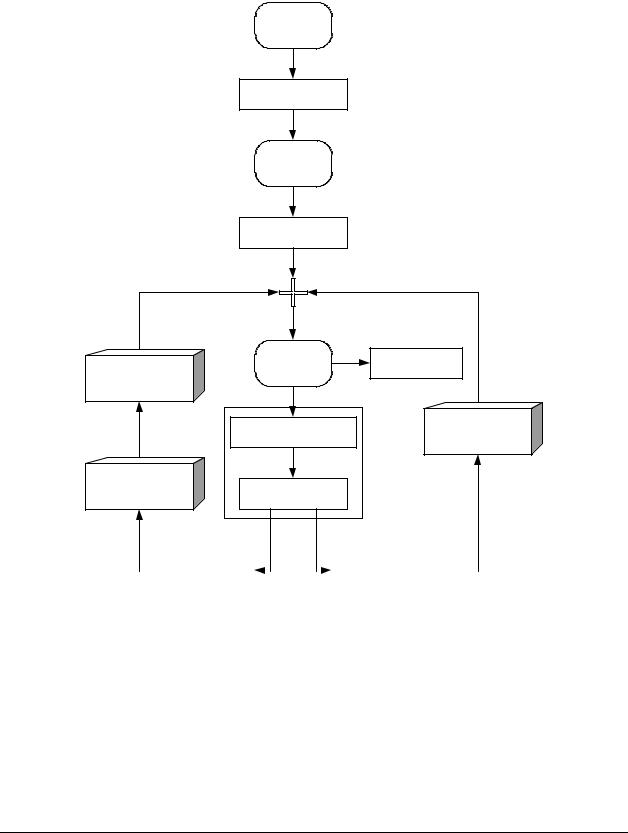
A model file has 12 procedures, which the user should fill out to specify the problem to be solved. The following figure shows the sequence in which the procedures are called from the simulation program:
1)Load Model
2)SetUpProblem
3)Start
4)PreCalc
State Change |
5) Stop |
Yes |
10) EndCalc |
|
|
|
|||
Procedure |
|
|
||
No |
|
|
||
|
|
|
||
6) |
ModelEquations |
Sample Check |
||
Procedure |
||||
|
|
|
||
Sample Check |
7) StateShift |
|
||
Procedure |
|
|||
Yes |
No |
|
||
|
8) OnSolution |
|
|
|
|
|
9) OnSolution |
|
|
|
|
|
|
|
|
Figure 8. Calling sequence for the procedures in the model file.
The rounded rectangles in Figure 8 represent user-actions in the Simulation program.
Note that the boxes 6 and 7 in general are called several times at each time step. This is because the solver iterates to find a solution. The procedure OnQuit, which is not represented in figure 8, is called when the user closes the simulation program or selects another model. The procedures
OnUIValueChange, OnSaveSettings and OnLoadSettings all have to do with controlling the user-interface. They will be explained later.
WinDali |
Morten Juel Skovrup |
22 6 Model file format
The calling sequence with no state shift is straightforward (for now ignore the Sample Check Procedure regarding Sample time – it will be covered in chapter 6.8). But the calling sequence with a state shift needs some explanation.
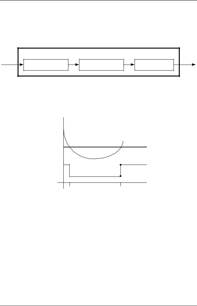
The State Change Procedure looks like this:
|
State Change Procedure |
|
OnStateChange |
ModelEquations |
OnSolution |
Figure 8a. State Change Procedure.
Lets say that we want to model a valve that is On when a temperature T is above 10°C, else it is Off. We want to record the temperature and the On-Off signal to the valve, and the initial temperature is 20°C. A plot of the temperature and the On-Off signal could look like this:
20°C |
|
|
T |
10°C |
|
On |
2b |
|
|
Off |
2a |
t1 |
t2 |
Figure 9. Temperature and On-Off signal.
When the solver reaches t2 where the valve goes On, it first calls OnSolution (block 8) to inform the model file that a solution has been found. But at t2 the equation system also shift state, which means that the solver has to start all over, and possibly with a new set of static equations.
The static equations have to be solved before the solver continues, and for this the solver needs guesses on the static variables.
In SetupProblem (as will be clear in chapter 6) default guesses on the static variables are given for each state, but if these guesses for some reason need to change, OnStateChange (see Figure 8a) is called. After OnStateChange, ModelEquations is called to solve the static equations in the new state, and before the solver continues, OnSolution is called to enable plotting of point 2b in Figure 9.
In the following the 12 procedures will be covered in detail.
WinDali |
Morten Juel Skovrup |