

Modulation 3
As can be seen from the table the power that is in the AF is divided equally between the two sidebands, furthermore the information in the AF is contained in both sidebands. It should also be noted that only one third of the signal is carrying the information.
Single Sideband (SSB)
There is redundancy in double sideband transmissions in that the information is contained in both the upper and lower sidebands. Additionally, the original RF carrier wave having served its purpose to get the audio information into radio frequencies is now redundant. So it is possible to remove one of the sidebands and the carrier wave because the remaining sideband contains all the information. This is known as single sideband (SSB) operation.
|
|
|
|
|
|
|
|
2185 kHz |
|
|
|
|
|
|
|
|
|
|
|
|
|
|
|
|
|
|
|
|
(25 W) |
|
|
|
Upper Sideband |
||
|
|
|
|
|
(150 W) |
|
|
(USB) |
|||
|
|
|
|
|
|
|
|
|
|
|
|
(100 W) |
RF |
2182 kHz |
|
|
|
|
|
2182.001 kHz |
|
|
|
|
|
|
|
|
|
|
|
|
|
|
|
|
|
|
|
|
(100 W) |
|
2182 kHz |
|
|
|
|
|
|
|
|
|
|
|
|
|
|||
|
|
|
|
|
|
|
|
|
|
|
|
(50 W) |
AF |
3 kHz |
|
|
|
|
|
2181.999 kHz |
|
|
|
|
|
|
|
|
|
|
|
|
|
|
|
|
|
|
|
|
|
|
|
|
Lower Sideband |
||
|
|
|
|
|
(25 W) |
|
|
(LSB) |
|
||
|
|
|
|
|
|
|
|
|
|||
|
|
|
|
|
|
|
|
|
|
|
|
|
|
|
|
|
|
|
|
|
|
|
|
|
|
|
|
|
|
|
|
2179 kHz |
|
|
|
|
|
|
|
|
|
|
|
|
|
|
|
|
|
|
Figure 3.4 Single sideband |
|
|
|
|||||
When using sky wave propagation for communication, the differing refraction occurring at different frequencies leads to an increase in distortion if the bandwidth is too large. The ionosphere comprises electrically charged particles which cause high levels of static interference on radio waves, the use of SSB significantly reduces the effect of this interference. The MF & HF frequencies used for long range communication are in great demand, hence the use of SSB transmissions increases the number of channels available. The use of SSB also reduces the amount of power required.
Thus the main advantages of SSB are:
•Double the number of channels available with double sideband
•Better signal/noise ratio (less interference)
•Less power required hence lighter equipment
Modulation 3
45

3 Modulation
Frequency Modulation (FM)
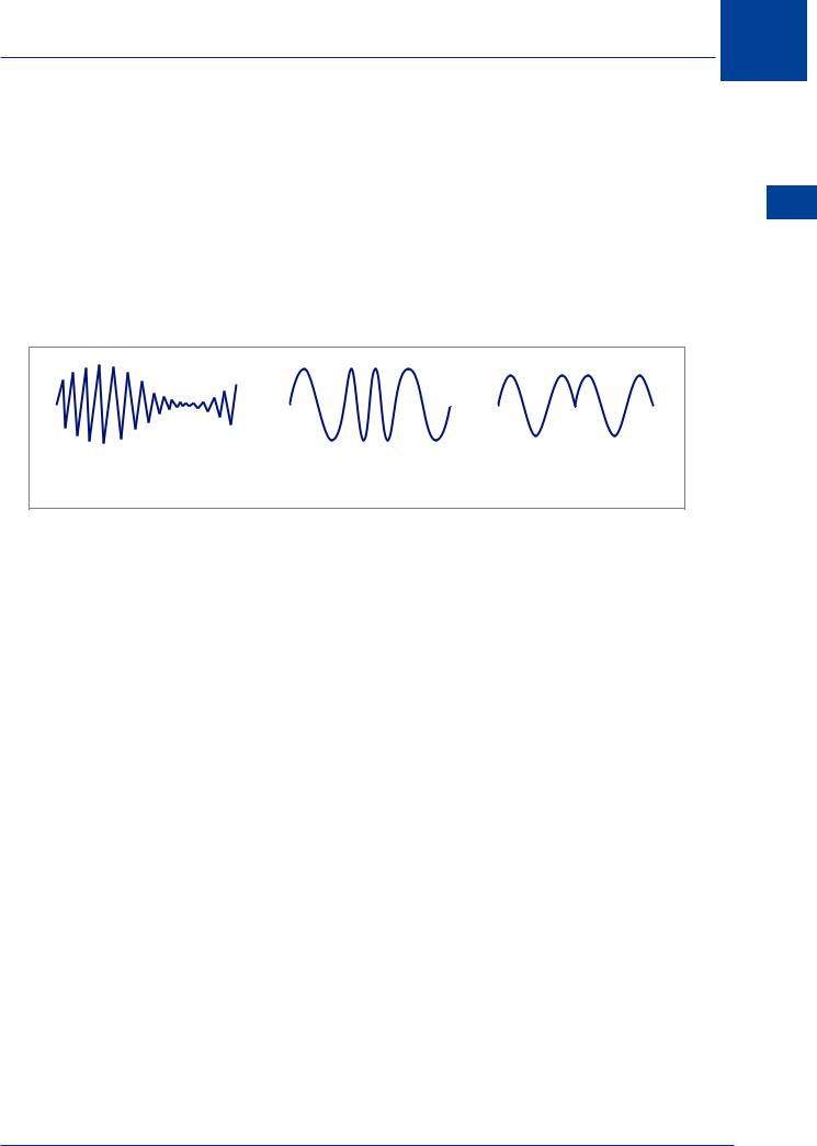
In Frequency Modulation, the amplitude of the audio frequency modifies the frequency of the carrier wave.
Modulation 3
Figure 3.5 Frequency modulation
The change in the carrier wave frequency is dependent on the rise and fall of the amplitude of the modulating wave/audio frequency: the greater the amplitude, the greater the frequency deviation. The frequency of the modulating wave determines the rate of change of frequency within the modulated carrier wave.
When FM is used for sound broadcasting (for example, music radio stations), the bandwidth permitted by international agreements is 150 kHz, compared to 9 kHz allowed for AM. In general, therefore, FM is unsuitable for use on frequencies below VHF.
For voice communications the bandwidth can be considerably reduced whilst still maintaining the integrity of the information; this is known as Narrow Band FM (NBFM). Typically, NBFM systems have a bandwidth of 8 kHz, which is greater than the 6 kHz permitted for Aeronautical Communications and the 3 kHz used in HF Communications; therefore, NBFM communication systems are not yet used in aviation.
46
Modulation 3
Phase Modulation
In phase modulation the phase of the carrier wave is modified by the input signal. There are two cases: the first is where the input is an analogue signal when the phase of the carrier wave is modified by the amplitude of the signal; secondly, with a digital signal it is known as phase shift keying, the phase change reflects a 0 or 1; e.g. 0° phase shift indicates a zero and 180° phase shift represents a 1. (Note: this is the simplest case as multiple data can be represented by using many degrees of phase shift.)
There are two cases used in navigation systems, MLS and GPS. GPS uses binary phase shift keying, MLS uses differential phase shift keying.
Modulation 3
Amplitude Modulation |
Frequency Modulation |
Phase Modulation |
Figure 3.6
Pulse Modulation
Pulse modulation is used extensively in radar systems and for data exchange in communications systems. An intermittent carrier wave is formed by the generation and transmission of a sequence of short period pulses.
Emission Designators
In order to easily identify the characteristics and information provided by electronic signals, a list of designators has been devised. They comprise 3 alphanumerics, where the first letter defines the nature of the modulation, the second digit the nature of the signal used for the modulation and the third letter the type of information carried.
47

Modulation |
3 |
48
EMISSION CHARACTERISTICS
|
First Symbol |
|
|
Second Symbol |
|
|
|
Third Symbol |
|
|
|
|
|
|
|
|
|
Type of modulation of the main carrier |
|
Nature of signals modulating the main carrier |
|
|
Type of information transmitted |
|||
|
|
|
|
|
|
|
|
|
N |
Emissions of an unmodulated |
|
0 |
No modulating signal |
|
N |
|
No information transmitted |
carrier |
|
|
|
|||||
|
|
|
|
|
|
|
|
|
|
|
|
|
|
|
|
|
|
|
|
|
|
Single channel containing quantized or |
|
|
|
|
A |
Amplitude modulation - Double |
|
1 |
digital information without the use of a |
|
A |
|
Telegraphy for aural reception |
sideband |
|
modulating sub-carrier, excluding time |
|
|
||||
|
|
|
|
|
|
|
||
|
|
|
|
division multiplex |
|
|
|
|
|
|
|
|
|
|
|
|
|
|
|
|
|
Single channel containing quantized |
|
|
|
|
H |
Amplitude modulation - Single |
|
2 |
or digital information with the use of a |
|
B |
|
Telegraphy for automatic |
sideband, full carrier |
|
modulating sub-carrier, excluding time |
|
|
reception |
|||
|
|
|
|
|
|
|||
|
|
|
|
division multiplex |
|
|
|
|
|
|
|
|
|
|
|
|
|
J |
Amplitude modulation - Single |
|
3 |
Single channel containing analogue |
|
C |
|
Facsimile |
sideband – suppressed carrier |
|
information |
|
|
||||
|
|
|
|
|
|
|
||
|
|
|
|
|
|
|
|
|
|
|
|
|
|
|
D |
|
Data transmission, telemetry, |
|
|
|
|
|
|
|
telecommand |
|
|
|
|
|
|
|
|
|
|
|
|
|
|
|
|
|
|
|
F |
Frequency modulation |
|
7 |
Two or more channels containing |
|
E |
|
Telephony, including sound |
|
quantized or digital information |
|
|
broadcasting |
||||
|
|
|
|
|
|
|
||
|
|
|
|
|
|
|
|
|
G |
Phase modulation |
|
8 |
Two or more channels containing |
|
F |
|
Television (video) |
|
analogue information |
|
|
|||||
|
|
|
|
|
|
|
|
|
|
|
|
|
|
|
|
|
|
|
|
|
|
Composite system with one or more |
|
|
|
|
|
|
|
|
channels containing quantized or |
|
|
|
|
|
|
|
9 |
digital information, together with one |
|
W |
|
Combinations of the above |
|
|
|
|
or more channels containing analogue |
|
|
|
|
|
|
|
|
information |
|
|
|
|
|
|
|
|
|
|
|
|
|
P |
Sequence of unmodulated pulses |
|
|
|
|
|
|
|
|
|
|
|
|
|
|
|
|
K |
Sequence of pulses modulated in |
|
X |
Cases not otherwise covered |
|
X |
|
Cases not otherwise covered |
amplitude |
|
|
|
|||||
|
|
|
|
|
|
|
|
|
|
|
|
|
|
|
|
|
|
Modulation 3

Modulation 3
For example, VHF radio telephony communications have the designation A3E. Reference to the table gives the following breakdown:
A - Amplitude modulation - Double sideband
3 - Single channel containing analogue information E - Telephony, including sound broadcasting
This means an RF carrier wave is being amplitude modulated with speech.
HF radio telephony communications have the designation J3E, this gives:
J - Amplitude modulation – single sideband with suppressed carrier 3 - Single channel containing analogue information
E - Telephony, including sound broadcasting
This means an RF carrier wave is being amplitude modulated with speech then the RF carrier wave is being removed along with one of the sidebands.
It is not necessary to know the details of the table.
Other designators relevant to the equipments discussed in phase 2 are:
ADF |
N0NA1A or N0NA2A |
VHF RTF |
A3E |
HF RTF |
J3E |
VOR |
A9W |
ILS |
A8W |
Marker Beacons |
A2A |
DME |
P0N |
MLS |
N0XG1D |
With the exception of ADF it is unlikely that knowledge of these designators will be examined.
Modulation 3
49