

7 Automatic Direction Finder (ADF)
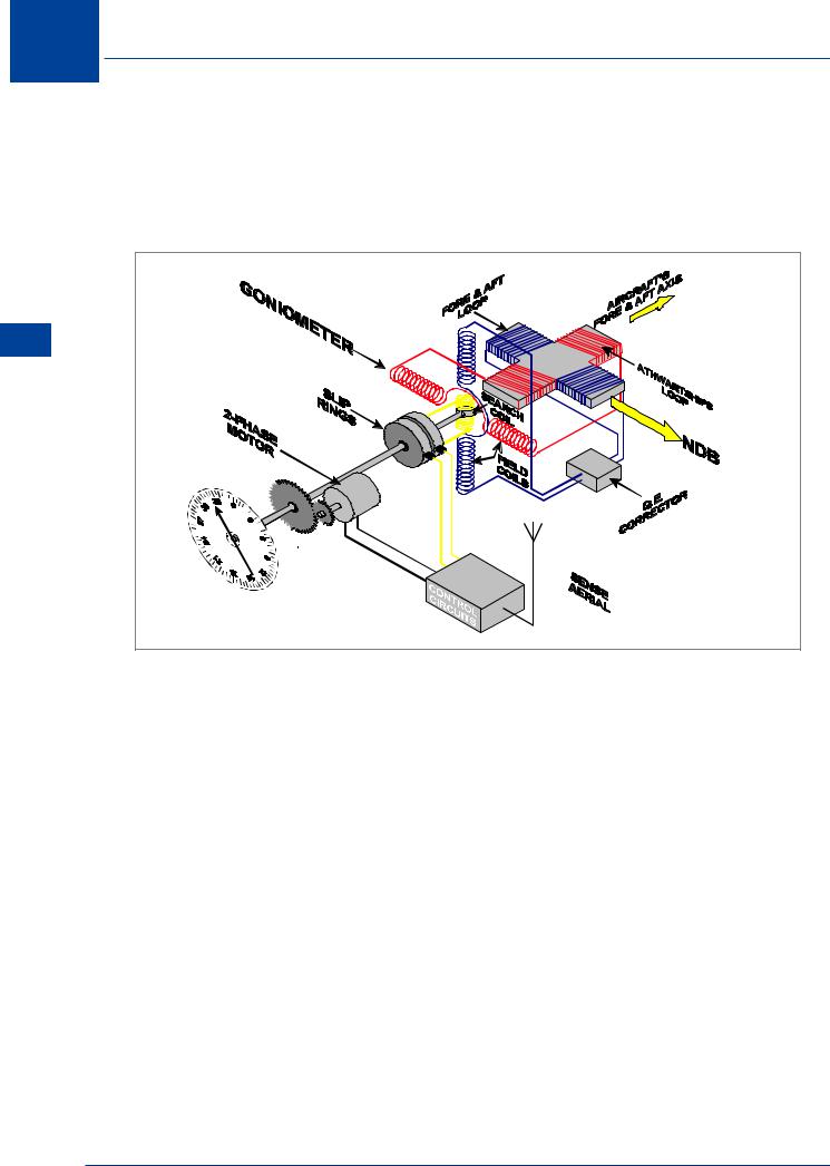
In reality it is not feasible to have a rotating loop outside the aircraft, so the loop is fixed and has four elements, two aligned with the fore-aft axis of the aircraft with the other two perpendicular to the fore-aft axis. The electrical fields are transmitted to a similar four elements in a goniometer reproducing the electro magnetic field detected by the aerial. The signal from the sense aerial is also fed to the goniometer where a search coil detects the unambiguous direction. The principle employed within the goniometer is as described above.
(ADF) Finder Direction Automatic 7
Figure 7.6 Fixed Loop ADF
Frequencies and Types of NDB
The allocated frequencies for NDBs are 190 - 1750 kHz in the LF and MF bands. Since the mode of propagation used is surface wave, most NDBs will be found between about 250 and 450 kHz. There are two types of NDB in current use:
Locator (L). These are low powered NDBs used for airfield or runway approach procedures or are co-located with, and supplement, the outer and middle markers of an ILS system. They normally have ranges of 10 to 25 NM and may only be available during an aerodrome’s published hours of operation.
En route NDBs. These have a range of 50 NM or more, and where serving oceanic areas may have ranges of several hundred miles. They are used for homing, holding, en route and airways navigation.
88

Automatic Direction Finder (ADF) |
7 |
|
Aircraft Equipment
The aircraft equipment comprises:
•A loop aerial
•A sense aerial
•A control unit
•A receiver
•A display
ADF |
BFO |
FRQ |
FLT/ET |
SET/RST |
ADF |
ANT |
BFO |
Automatic Direction Finder (ADF) 7
Figure 7.7 Two ADF Receivers
Emission Characteristics and Beat Frequency Oscillator (BFO)
The NDBs have a 2 or 3 letter identification and there are two types of emission:
N0NA1A N0NA2A
The N0N part of the emission is the transmission of an unmodulated carrier wave, which would not be detectable on a normal receiver, so a BFO is provided on ADF equipment. When selected, the BFO produces an offset frequency within the receiver which when combined with the received frequency produces a tone of say 400 or 1020 Hz.
The A1A part is the emission of an interrupted unmodulated carrier wave which requires the BFO to be on for aural reception. A2A is the emission of an amplitude modulated signal which can be heard on a normal receiver.
Hence, when using N0NA1A beacons, the BFO should be selected ON for (manual) tuning, identification and monitoring. N0NA2A beacons require the BFO ON for (manual) tuning but OFF for identification and monitoring. (The BFO may be labelled TONE or TONE/VOICE on some equipments).
89

7 Automatic Direction Finder (ADF)
Presentation of Information
The information may be presented on a relative bearing indicator (RBI) or a radio magnetic indicator (RMI). In either case the information being presented is relative bearing.
(ADF) Finder Direction Automatic 7
|
|
|
|
|
|
|
|
|
|
|
|
|
|
|
|
|
|
|
|
|
|
|
|
|
|
|
|
|
|
|
|
|
|
|
|
|
|
|
|
|
|
|
|
|
|
|
|
|
|
|
|
|
|
|
|
|
|
|
|
|
|
|
|
|
|
|
|
|
|
|
|
|
|
|
|
|
|
|
|
|
|
|
|
|
|
|
|
|
|
|
|
|
|
|
|
|
|
Figure 7.8 RBI |
Figure 7.9 RMI |
||||||||
The RBI has a standard compass rose where 360° is aligned with the fore-aft axis of the aircraft, although with some RBIs it is possible to manually set heading to directly read the magnetic bearing. In the diagram the aircraft is heading 300°(M), the RBI is showing a relative bearing of 136°, thus the magnetic bearing is 300° + 136° - 360° = 076°. The information from the ADF to the RMI is still relative, but the RMI compass card is fed with magnetic heading, so the bearing shown is the magnetic bearing of the NDB.
The needle always points to the beacon (QDM) and the tail of the needle gives the QDR.
90

Automatic Direction Finder (ADF) |
7 |
|
Uses of the Non-directional Beacon
•En route navigational bearings.
•Homing to or flying from the NDB when maintaining airway centre lines.
•Holding overhead at an assigned level in a race-track pattern.
•Runway instrument approach procedures.
Plotting ADF Bearings
The plotting of ADF bearings is dealt with in depth in the Navigation General syllabus. At this stage it is sufficient to remind the reader that the bearing is measured at the aircraft so variation to convert to a true bearing must be applied at the aircraft. Account will also need to be taken of the convergency between the aircraft and beacon meridians.
Track Maintenance Using the RBI
An aircraft is required to maintain track(s):
•When flying airway centre line between NDBs.
•When holding over an NDB or Locator.
•When carrying out a let-down procedure at an airfield based solely upon NDB(s)/Locator(s) or NDB(s)/Locators combined with other navaids.
•When requested by ATC to intercept and maintain a track or airway centre line.
•When carrying out interceptions.
Homing
Figure 7.10 shows an aircraft maintaining 360° relative bearing, in zero wind (zero drift). The aircraft is heading 077° and therefore will track inbound on 077°.
Figure 7.10 Homing in Zero Drift
Automatic Direction Finder (ADF) 7
91