


Instrument Landing System (ILS) |
|
9 |
|
||
|
|
|
ILS Principle of Operation
The Localizer
The localizer antenna produces two overlapping lobes along the runway approach direction (QDM) as shown in Figure 9.8. The lobes are transmitted on a single VHF ILS frequency. In order that an aircraft’s ILS receiver can distinguish between the lobes:
•the right hand lobe (the blue sector) has a 150 Hz modulation.
•the left hand lobe (the yellow sector) has a 90 Hz modulation.
The depth of modulation (DoM) increases away from the centre line i.e. the amplitude of the modulating signal increases away from the centre line. An aircraft approaching the runway centre line from the right will receive more of the 150 Hz signal than the 90 Hz modulation. This difference in depth of modulation (DDM) relates to the angular displacement of the aircraft from the centre line; it energizes the vertical needle of the ILS indicator, i.e. Go Left.
Similarly an aircraft approaching the runway centre line from the left will receive more of the 90 Hz signal than the 150 Hz modulation; the DDM energises the vertical needle, i.e. Go Right.
A DDM of zero indicates a balance between modulations, a zero needle-deflection and hence the runway centre line.
Back Course ILS
There is a mirror image behind the localizer aerial so ILS indications are received on aircraft equipment. Back Course ILS is used in some countries but is not permitted in the United Kingdom. Ignore any back course indications in the United Kingdom.
The back course ILS has the following disadvantages:
•The glide path indications are incorrect (they would, if used guide the aircraft to the wrong end of the runway).
•The CDI needle (localizer) is sense reversed. (Flying to R/W).
•There are no range-check markers.
Figure 9.8 Localizer radiation pattern
Instrument Landing System (ILS) 9
153

9 |
|
Instrument Landing System (ILS) |
|
||
|
|
|
(ILS) System Landing Instrument 9
|
FIRST FALSE |
150 Hz MODULATED |
EQUISIGNAL |
|
|
LOBES |
|
GLIDE PATH |
|
TRANSMITTER |
|
Figure 9.9 Glide path radiation pattern
Glide Slope
The glide slope UHF transmitter is located to one side of the runway approximately 200 m from the runway edge, 300 m upwind of the threshold.
The same principle is used as for the localizer, but a UHF carrier wave is used and the lobes are in the vertical plane. The upper lobe (large lobe) has a 90 Hz modulation, and the bottom lobe (small lobe) has a 150 Hz modulation. The glide path, usually 3° (ICAO require glide path angle between 2° and 4°), is defined where the DDM of the overlapping lobes is zero and the ILS indicator’s glide path needle will indicate zero deviation. The radiation pattern is shown in
Figure 9.9.
False Glide Slope(s)
These are defined as the paths of points, in the vertical plane, containing the runway centre line at which the DDM is zero; other than that path of points forming the ILS glide path. The twin lobes are repeated due to:
•Metallic structures situated at the transmission point, and ground reflections.
•The height and propagation characteristics of the aerial.
The first false glide slope occurs at approximately twice the glide path angle, 6° above ground for a standard 3° glide path. False glide slopes always occur above the true glide slope and should not constitute a danger but pilots should be aware of their presence.
Normal flying practice is to establish on the localizer and intercept the glide slope from below. However at airfields such as London Heathrow a continuous descent approach is used in which the aircraft are positioned by ground radar to capture the glide slope from above. It is advisable to always confirm the aircraft height in relation to distance to go by reference to DME, markers, locators etc.
154
Instrument Landing System (ILS) |
9 |
|
ILS Reference Datum Point
The ILS reference datum point is a point at a specified height (around 50 feet) located vertically above the intersection of the runway centre line and threshold, through which the downward extended portion of the ILS glide path extends. This value is to be found in the remarks column for the particular airfield in the UK AIP, AD section.
Visual Glide Path Indicators
The approach light systems such as PAPIs give a visual indication of the glide path to the runway that would be the same as that for the ILS so that during the final phase of the approach the pilot should get similar indications of glide path from both systems. However the visual indications are designed for a mean eye height (meht) of the pilot and they would therefore vary slightly since the pilot’s position will vary depending upon the size of the aircraft.
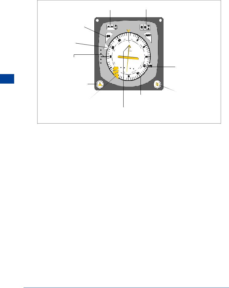
ILS Presentation and Interpretation
Indicators
Localizer and glide path information can be displayed:
•on a Course Deviation Indicator (CDI) or
•on the Horizontal Situation Indicator (HSI).
Interpretation of a CDI display is shown in Figure 9.10. The HSI display is shown at Figure 9.11. The main difference to note is that on the HSI there is a course selector which should be set on the QDM of the runway. The deviation indications then appear in the correct sense.
3. GLIDE PATH NEEDLE.
A FULL SCALE DEFLECTION SHOWS THE AIRCRAFT 0.7° OR MORE ABOVE OR BELOW THE ILS GLIDE PATH. THE SCALE IS LINEAR
Instrument Landing System (ILS) 9
1. LOCALIZER NEEDLE SHOWS 2½ DOTS ‘FLY LEFT’.
|
24 |
27 |
30 |
|
|
||
21 |
|
|
33 |
|
|
|
|
18 |
|
|
0 |
15 |
|
|
3 |
|
|
|
|
OBS |
12 |
9 |
6 |
|
|||
|
|
||
|
|
|
2. LOCALIZER NEEDLE 5 DOT DISPLAY.
EACH DOT = ½° DISPLACEMENT FROM CENTRE LINE IN ILS MODE.
(IN VOR MODE EACH DOT = 2° DISPLACEMENT)
4. GLIDE PATH NEEDLE. ‘2½ DOTS FLY UP’ IS THE MAXIMUM SAFE DEVIATION BELOW THE GLIDE SLOPE FOR A 5 DOT DISPLAY.
5. THE INNER CIRCLE IS THE FIRST DOT.
6. EITHER NEEDLE MOVES TO THE CENTRE AND ITS ‘OFF’ FLAG APPEARS WHEN:-
a)THE AIRCRAFT IS OUTSIDE THE RADIATION PATTERN.
b)THERE IS A TRANSMISSION FAULT.
c)THE GROUND OR THE
AIRBORNE EQUIPMENT IS SWITCHED OFF.
d) THERE IS A FAILURE IN THE GROUND OR THE AIRBORNE EQUIPMENT.
Figure 9.10 ILS course deviation indicator
155
9 |
|
Instrument Landing System (ILS) |
|
||
|
|
|
(ILS) System Landing Instrument 9
DME RANGE |
SELECTED COURSE |
|
ILS FAILURE FLAG |
AZIMUTH |
|
FAILURE FLAG |
||
|
HEADING |
|
|
INDEX |
|
|
ILS GLIDE SCOPE |
DIRECTIONAL GYRO |
|
DEVIATION |
||
FAILURE FLAG |
||
|
||
HEADING |
|
|
SELECTOR KNOB |
|
|
|
COMMAND |
|
COMPASS CARD |
TRACK FLAG |
LOSS OF POWER FLAG
COMMAND TRACK POINTER AND
LATERAL DEVIATION BAR
Figure 9.11 A typical HSI
Localizer Indications
Front course approach indications for fly left and right are shown in Figure 9.12. Full scale deflection of the needle indicates that the aircraft is 2.5° or more left or right of the centre-line i.e. the sensitivity is 0.5° per dot.
Back Beam Approach
Where a localizer is designed to radiate back course information it can:
•give azimuth guidance on overshoot from main precision approach runway, when the CDI or HSI needle should be obeyed, or
•give back course approach to the reciprocal of the main precision approach runway. In this case the CDI needle will give reverse indications whereas an HSI will give correct indications provided that the front course QDM has been selected.
156

Instrument Landing System (ILS) |
|
9 |
|
||
|
|
|
QDM |
QDR |
LOCALIZER ON- |
|
|
COURSE LINE |
Figure 9.12: Localizer
Glide Path Indications
The glide path indication for fly up or fly down is shown in Figure 9.13. Full scale deflection indicates that the aircraft is 0.7° or more above or below the glide path. The sensitivity is 0.14° per dot. Note that the maximum safe deviation below the glideslope is half full-scale deflection i.e. 2.5 dots fly up.
Instrument Landing System (ILS) 9
Figure 9.13 Glide path
Note: If, on approach, the left/right deflections or the fly-up indications exceed half full scale then an immediate go-around should be initiated because safe terrain clearance may be compromised.
157