

Chapter 16: XML DTD Code Generation and Reverse Engineering
how classes are mapped to a component. If Assign All is selected, all new and existing classes will automatically be mapped to the component. If Remove Assignment is selected, all classes will be removed from that component.
Generating Code
Once you have created the necessary elements, entities, and other Rose model items, you can generate a DTD file from the model. To do so, follow these steps:
1.
Set the code−generation properties, as discussed throughout this chapter.
2.
Select Tools → XML_DTD → Syntax Check. This will run a DTD−specific syntax check of your model, and let you know if there are any invalid items or other errors.
3.
Create a component to represent the DTD file. This is an optional step, but if you do not create a component, Rose will create a separate DTD for each class.
4.
Map the classes to the DTD component. You can do this using the Realizes tab on the standard component specification window. In the Realizes tab, right−click the classes to map to the component and select Assign.
5.
Select the class(es) you wish to generate.
6.
Select Tools → XML_DTD → Generate Code.
7.
To view the generated DTD for a class, right−click the class on a diagram and select XML_DTD → Browse DTD Source.
Generated Code
In the following sections, we'll take a look at the DTD generated for various types of model elements, including classes, attributes, and association relationships. In each of these sections, we'll include some sample code to give you an idea of what will be generated from your Rose model.
Let's begin by looking at the code generated for various types of classes.
554

Chapter 16: XML DTD Code Generation and Reverse Engineering
Classes
Classes in the model will be translated into elements, entities, or content models of an element. The translation occurs based on the stereotype that the class was assigned. Let's start with element classes.
Elements
A DTD element is represented in the Rose model as a class with a stereotype of <<DTDElement>>.
Through association relationships, the element is connected to a group, which is then related to any other elements that are in the content model. Note that all elements in the content model must be contained in the Rose model in order for the DTD to be generated.
We'll get into the details of the content model shortly, but first let's look at the element stereotypes. You can further refine an element by changing its stereotype. The available element stereotypes include:
DTDElementAny: This stereotype suggests that the element's content model can contain text and other elements. The keyword ANY is included in the generated DTD. For the chapter element, the following is generated:
<!ELEMENT Chapter ANY>
DTDElementEmpty: This stereotype suggests that the element cannot contain text or other elements in its content model. The entity may, however, have attributes. In this case, the keyword EMPTY is included in the generated DTD. Our chapter element would now look like this:
<!ELEMENT Chapter EMPTY>
DTDElementPCDATA: This stereotype suggests that the element may contain text in its content model. With this stereotype, the chapter element would look like this:
<!ELEMENT Chapter (#PCDATA)>
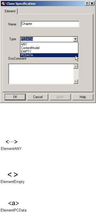
To set the stereotype of an element, open its specification window. In the Type field, select the appropriate stereotype (ANY, EMPTY, or PCDATA), as shown in Figure 16.9.
555
Chapter 16: XML DTD Code Generation and Reverse Engineering
Figure 16.9: Setting an element stereotype
Rose 2001A and 2002 include icons for each of the element types. You can use these icons by right−clicking a class and selecting Options → Stereotype Display → Icon. The following icons are used by Rose:
Element Any
Element Empty
Element PCDATA
Content Model
As mentioned earlier, an element is connected to the elements in its content model through association relationships. Figure 16.10 is an example from our book model.
556

Chapter 16: XML DTD Code Generation and Reverse Engineering
Figure 16.10: Content Model in Rose
In this example, a book has a title, a table of contents, an introduction, and sections. A class with a stereotype of DTDGroup is used to collect the elements into the content model for the book. There are two types of groups, corresponding to the two ways the elements in a content model are separated.
In the DTD, the elements in the content model may be separated by commas, indicating that the elements must appear in the sequence in which they are listed. Alternately, the elements (or a subset of them) may be separated by a choice operator (|), which implies the word "or." (For example, ELEMENT A (B|C) suggests that element A may contain B or C.)
This information is indicated by the type of DTDGroup class you are using. This notation represents one type:
<<DTDSequenceGroup>>
In Rose 2001A and 2002, a class with a stereotype of DTDSequenceGroup is displayed as an ampersand with a circle around it, as shown in Figure 16.11. This grouping suggests that the elements were separated by commas (i.e., there is a sequence to the elements).
Figure 16.11: An example of a sequence group
Note In Rose 2001, a sequence group is displayed as a filled square.
This notation represents another type:
<<DTDChoiceGroup>>
In Rose 2001A and 2002, a class with a stereotype of DTDChoiceGroup is displayed as an "or" symbol (choice operator) with a circle around it, as shown in Figure 16.12. This stereotype suggests that the elements
557

Chapter 16: XML DTD Code Generation and Reverse Engineering
are part of a choice in the content model.
Figure 16.12: An example of a choice group
Note In Rose 2001, a choice group is displayed as a hollow square.
To create a sequence or choice group:
1.
Right−click the element and select Open Standard Specification.
2.
Select the Nested tab.
3.
Right−click anywhere inside the white space and select Insert.
4.
Enter the name of the sequence or choice group.
5.
Press OK.
6.
The new group will appear in the browser under the entity. Right−click the group and select Open Specification.
7.
Set the stereotype to DTDGroup and press OK. The DTD Class Specification window for a group will appear.
8.
Set the Grouping Type to Choice or Sequence.
9.
Set the Occurrence field to the appropriate multiplicity.
10.
Press OK.
Details on the association relationships tell us whether or not each element is required and the multiplicity for each element. Table 16.5 lists the association multiplicity notations and their DTD equivalents.
558
Chapter 16: XML DTD Code Generation and Reverse Engineering
Table 16.5: Content Model Multiplicity
Multiplicity in |
DTD Symbol |
Meaning |
Rose |
|
|
0..1 |
? |
Element is not required, but if it is present, there may be only one. |
0..n |
* |
Element is not required, and there may be more than one. |
1..n |
+ |
Element is required, and there may be more than one. |
Figure 16.13 includes examples of each multiplicity option, in Rose and in DTD.
Figure 16.13: Content model multiplicity in Rose and in DTD
The order of the elements in the content model is translated into the Rose model in the form of constraints. Each association relationship can have a constraint, which is shown in braces {}. In the example ELEMENT A (B, C, D), the association relationship between A and B would have a constraint of 1, the relationship between A and C would have a constraint of 2, and the relationship between A and D would have a constraint of 3. Figure 16.14 shows a Rose model and the corresponding DTD file. By examining the constraints, you can see the order the elements are listed in the content model.
Figure 16.14: Content model element order in Rose and in DTD
Elements may also contain attributes. See the "Attributes" section later in this chapter for a discussion of modeling attributes and the generation of attributes in a DTD file.
Next, let's examine how entities are modeled in Rose and translated into the DTD file.
559

Chapter 16: XML DTD Code Generation and Reverse Engineering
Entities
Like elements, entities are represented as classes in the Rose model. An entity is given the stereotype <<DTDEntity>>. Using the specification window shown in Figure 16.15, you can set the details of the entity that will be generated in the DTD.
Figure 16.15: DTD entity specification window
If the entity is an internal entity, enter the entity value in the Value field in the specification window. The value will appear in the generated DTD, as follows:
<!ENTITY Company "ACME DTD Files, Inc.">
If the entity is an external entity, select the External Entity check box and fill in the System ID, Public ID, and Notation Name fields:
System ID Enter the location of the entity in this field. For example, documentwithentity.xml.
Public ID Enter an alternate address for the entity in this field.
Notation Name If the external entity has a notation, enter the name of the notation here. Rose will include the NDATA keyword in the generated DTD, similar to the following:
<!ENTITY MyVideo SYSTEM "C:\Videos\Vacation.vid" NDATA Video>
Whether the entity is internal or external, you can enter a comment into the DocComment field. Anything you enter in this field will appear as a comment in the generated DTD.
To create an entity:
1.
560

Chapter 16: XML DTD Code Generation and Reverse Engineering
Create a new class.
2.
Assign the stereotype <<DTDEntity>> to the class.
3.
Use the specification window to set the entity details as described above.
4.
Create a notation if needed (see the following "Notations" section).
In Rose 2001A and 2002, you can use a special icon to represent an entity. Create an entity as described above. If the icon is not showing, right−click the class and select Options → Stereotype Display → Icon. The Entity icon looks like this:
Notations
A notation is modeled as a class with a stereotype of <<DTDNotation>>. As with entities, the details for the notation are set using the specification window (see Figure 16.16).
Figure 16.16: DTD notation pecification window
Using this window, you set the location of the application used to process the entity. You may also set an alternate location using the Public ID field.
The notation is linked to the appropriate entity by a bidirectional association relationship. For example:
561