- •Table of Contents
- •Mastering UML with Rational Rose 2002
- •Chapter 1: Introduction to UML
- •Encapsulation
- •Inheritance
- •Polymorphism
- •What Is Visual Modeling?
- •Systems of Graphical Notation
- •Booch Notation
- •Object Management Technology (OMT)
- •Unified Modeling Language (UML)
- •Understanding UML Diagrams
- •Business Use Case Diagrams
- •Use Case Diagrams
- •Activity Diagrams
- •Sequence Diagrams
- •Collaboration Diagrams
- •Class Diagrams
- •Statechart Diagrams
- •Component Diagrams
- •Deployment Diagrams
- •Visual Modeling and the Software Development Process
- •Inception
- •Elaboration
- •Construction
- •Transition
- •Summary
- •Chapter 2: A Tour of Rose
- •What Is Rose?
- •Getting Around in Rose
- •Parts of the Screen
- •Exploring Four Views in a Rose Model
- •Use Case View
- •Logical View
- •Component View
- •Deployment View
- •Working with Rose
- •Creating Models
- •Saving Models
- •Exporting and Importing Models
- •Publishing Models to the Web
- •Working with Controlled Units
- •Using the Model Integrator
- •Working with Notes
- •Working with Packages
- •Adding Files and URLs to Rose Model Elements
- •Adding and Deleting Diagrams
- •Setting Global Options
- •Working with Fonts
- •Working with Colors
- •Summary
- •Chapter 3: Business Modeling
- •Introduction to Business Modeling
- •Why Model the Business?
- •Do I Need to Do Business Modeling?
- •Business Modeling in an Iterative Process
- •Business Actors
- •Business Workers
- •Business Use Cases
- •Business Use Case Diagrams
- •Activity Diagrams
- •Business Entities
- •Organization Unit
- •Where Do I Start?
- •Identifying the Business Actors
- •Identifying the Business Workers
- •Identifying the Business Use Cases
- •Showing the Interactions
- •Documenting the Details
- •Creating Business Use Case Diagrams
- •Deleting Business Use Case Diagrams
- •The Use Case Diagram Toolbar
- •Adding Business Use Cases
- •Business Use Case Specifications
- •Assigning a Priority to a Business Use Case
- •Viewing Diagrams for a Business Use Case
- •Viewing Relationships for a Business Use Case
- •Working with Business Actors
- •Adding Business Actors
- •Adding Actor Specifications
- •Assigning an Actor Stereotype
- •Setting Business Actor Multiplicity
- •Viewing Relationships for a Business Actor
- •Working with Relationships
- •Association Relationship
- •Generalization Relationship
- •Working with Organization Units
- •Adding Organization Units
- •Deleting Organization Units
- •Activity Diagrams
- •Adding an Activity Diagram
- •Adding Details to an Activity Diagram
- •Summary
- •Chapter 4: Use Cases and Actors
- •Use Case Modeling Concepts
- •Actors
- •Use Cases
- •Traceability
- •Flow of Events
- •Relationships
- •Use Case Diagrams
- •Activity Diagrams
- •Activity
- •Start and End States
- •Objects and Object Flows
- •Transitions
- •Synchronization
- •Working with Use Cases in Rational Rose
- •The Use Case Diagram Toolbar
- •Creating Use Case Diagrams
- •Deleting Use Case Diagrams
- •Adding Use Cases
- •Deleting Use Cases
- •Use Case Specifications
- •Naming a Use Case
- •Viewing Participants of a Use Case
- •Assigning a Use Case Stereotype
- •Assigning a Priority to a Use Case
- •Creating an Abstract Use Case
- •Viewing Diagrams for a Use Case
- •Viewing Relationships for a Use Case
- •Working with Actors
- •Adding Actors
- •Deleting Actors
- •Actor Specifications
- •Naming Actors
- •Assigning an Actor Stereotype
- •Setting Actor Multiplicity
- •Creating an Abstract Actor
- •Viewing Relationships for an Actor
- •Viewing an Actor's Instances
- •Working with Relationships
- •Association Relationship
- •Includes Relationship
- •Extends Relationship
- •Generalization Relationship
- •Working with Activity Diagrams
- •The Activity Diagram Toolbar
- •Creating Activity Diagrams
- •Deleting Activity Diagrams
- •Exercise
- •Problem Statement
- •Create a Use Case Diagram
- •Summary
- •Chapter 5: Object Interaction
- •Interaction Diagrams
- •What Is an Object?
- •What Is a Class?
- •Where Do I Start?
- •Finding Objects
- •Finding the Actor
- •Using Interaction Diagrams
- •Sequence Diagrams
- •The Sequence Diagram Toolbar
- •Collaboration Diagrams
- •The Collaboration Diagram Toolbar
- •Working with Actors on an Interaction Diagram
- •Working with Objects
- •Adding Objects to an Interaction Diagram
- •Deleting Objects from an Interaction Diagram
- •Setting Object Specifications
- •Naming an Object
- •Mapping an Object to a Class
- •Setting Object Persistence
- •Using Multiple Instances of an Object
- •Working with Messages
- •Adding Messages to an Interaction Diagram
- •Adding Messages to a Sequence Diagram
- •Deleting Messages from a Sequence Diagram
- •Reordering Messages in a Sequence Diagram
- •Message Numbering in a Sequence Diagram
- •Viewing the Focus of Control in a Sequence Diagram
- •Adding Messages to a Collaboration Diagram
- •Deleting Messages from a Collaboration Diagram
- •Message Numbering in a Collaboration Diagram
- •Adding Data Flows to a Collaboration Diagram
- •Setting Message Specifications
- •Naming a Message
- •Mapping a Message to an Operation
- •Setting Message Synchronization Options
- •Setting Message Frequency
- •End of a Lifeline
- •Working with Scripts
- •Switching Between Sequence and Collaboration Diagrams
- •Exercise
- •Problem Statement
- •Create Interaction Diagrams
- •Summary
- •Chapter 6: Classes and Packages
- •Logical View of a Rose Model
- •Class Diagrams
- •What Is a Class?
- •Finding Classes
- •Creating Class Diagrams
- •Deleting Class Diagrams
- •Organizing Items on a Class Diagram
- •Using the Class Diagram Toolbar
- •Working with Classes
- •Adding Classes
- •Class Stereotypes
- •Analysis Stereotypes
- •Class Types
- •Interfaces
- •Web Modeling Stereotypes
- •Other Language Stereotypes
- •Class Specifications
- •Naming a Class
- •Setting Class Visibility
- •Setting Class Multiplicity
- •Setting Storage Requirements for a Class
- •Setting Class Persistence
- •Setting Class Concurrency
- •Creating an Abstract Class
- •Viewing Class Attributes
- •Viewing Class Operations
- •Viewing Class Relationships
- •Using Nested Classes
- •Viewing the Interaction Diagrams That Contain a Class
- •Setting Java Class Specifications
- •Setting CORBA Class Specifications
- •Working with Packages
- •Adding Packages
- •Deleting Packages
- •Exercise
- •Problem Statement
- •Creating a Class Diagram
- •Summary
- •Chapter 7: Attributes and Operations
- •Working with Attributes
- •Finding Attributes
- •Adding Attributes
- •Deleting Attributes
- •Setting Attribute Specifications
- •Setting the Attribute Containment
- •Making an Attribute Static
- •Specifying a Derived Attribute
- •Working with Operations
- •Finding Operations
- •Adding Operations
- •Deleting Operations
- •Setting Operation Specifications
- •Adding Arguments to an Operation
- •Specifying the Operation Protocol
- •Specifying the Operation Qualifications
- •Specifying the Operation Exceptions
- •Specifying the Operation Size
- •Specifying the Operation Time
- •Specifying the Operation Concurrency
- •Specifying the Operation Preconditions
- •Specifying the Operation Postconditions
- •Specifying the Operation Semantics
- •Displaying Attributes and Operations on Class Diagrams
- •Showing Attributes
- •Showing Operations
- •Showing Visibility
- •Showing Stereotypes
- •Mapping Operations to Messages
- •Mapping an Operation to a Message on an Interaction Diagram
- •Exercise
- •Problem Statement
- •Add Attributes and Operations
- •Summary
- •Chapter 8: Relationships
- •Relationships
- •Types of Relationships
- •Finding Relationships
- •Associations
- •Using Web Association Stereotypes
- •Creating Associations
- •Deleting Associations
- •Dependencies
- •Creating Dependencies
- •Deleting Dependencies
- •Package Dependencies
- •Creating Package Dependencies
- •Deleting Package Dependencies
- •Aggregations
- •Creating Aggregations
- •Deleting Aggregations
- •Generalizations
- •Creating Generalizations
- •Deleting Generalizations
- •Working with Relationships
- •Setting Multiplicity
- •Using Relationship Names
- •Using Stereotypes
- •Using Roles
- •Setting Export Control
- •Using Static Relationships
- •Using Friend Relationships
- •Setting Containment
- •Using Qualifiers
- •Using Link Elements
- •Using Constraints
- •Exercise
- •Problem Statement
- •Adding Relationships
- •Summary
- •Chapter 9: Object Behavior
- •Statechart Diagrams
- •Creating a Statechart Diagram
- •Adding States
- •Adding State Details
- •Adding Transitions
- •Adding Transition Details
- •Adding Special States
- •Using Nested States and State History
- •Exercise
- •Problem Statement
- •Create a Statechart Diagram
- •Summary
- •Chapter 10: Component View
- •What Is a Component?
- •Types of Components
- •Component Diagrams
- •Creating Component Diagrams
- •Adding Components
- •Adding Component Details
- •Adding Component Dependencies
- •Exercise
- •Problem Statement
- •Summary
- •Chapter 11: Deployment View
- •Deployment Diagrams
- •Opening the Deployment Diagram
- •Adding Processors
- •Adding Processor Details
- •Adding Devices
- •Adding Device Details
- •Adding Connections
- •Adding Connection Details
- •Adding Processes
- •Exercise
- •Problem Statement
- •Create Deployment Diagram
- •Summary
- •Chapter 12: Introduction to Code Generation and Reverse Engineering Using Rational Rose
- •Preparing for Code Generation
- •Step One: Check the Model
- •Step Two: Create Components
- •Step Three: Map Classes to Components
- •Step Five: Select a Class, Component, or Package
- •Step Six: Generate Code
- •What Gets Generated?
- •Introduction to Reverse Engineering Using Rational Rose
- •Model Elements Created During Reverse Engineering
- •Summary
- •Chapter 13: ANSI C++ and Visual C++ Code Generation and Reverse Engineering
- •Generating Code in ANSI C++ and Visual C++
- •Converting a C++ Model to an ANSI C++ Model
- •Class Properties
- •Attribute Properties
- •Operation Properties
- •Package (Class Category) Properties
- •Component (Module Specification) Properties
- •Role Properties
- •Generalization Properties
- •Class Model Assistant
- •Component Properties
- •Project Properties
- •Visual C++ and ATL Objects
- •Generated Code
- •Code Generated for Classes
- •Code Generated for Attributes
- •Code Generated for Operations
- •Visual C++ Code Generation
- •Reverse Engineering ANSI C++
- •Reverse Engineering Visual C++
- •Summary
- •Overview
- •Introduction to Rose J
- •Beginning a Java Project
- •Selecting a Java Framework
- •Linking to IBM VisualAge for Java
- •Linking to Microsoft Visual J++
- •Project Properties
- •Class Properties
- •Attribute Properties
- •Operation Properties
- •Module Properties
- •Role Properties
- •Generating Code
- •Generated Code
- •Classes
- •Attributes
- •Operations
- •Bidirectional Associations
- •Unidirectional Associations
- •Associations with a Multiplicity of One to Many
- •Associations with a Multiplicity of Many to Many
- •Reflexive Associations
- •Aggregations
- •Dependency Relationships
- •Generalization Relationships
- •Interfaces
- •Java Beans
- •Support for J2EE
- •EJBs
- •Servlets
- •JAR and WAR Files
- •Automated J2EE Deployment
- •Reverse Engineering
- •Summary
- •Starting a Visual Basic Project
- •Class Properties
- •Attribute Properties
- •Operation Properties
- •Module Specification Properties
- •Role Properties
- •Generalization Properties
- •Generated Code
- •Classes
- •Attributes
- •Operations
- •Bidirectional Associations
- •Unidirectional Associations
- •Associations with a Multiplicity of One to Many
- •Associations with a Multiplicity of Many to Many
- •Reflexive Associations
- •Aggregations
- •Dependency Relationships
- •Generalization Relationships
- •Reverse Engineering
- •Summary
- •Overview
- •Introduction to XML DTD
- •Elements
- •Attributes
- •Entities and Notations
- •Project Properties
- •Class Properties
- •Attribute Properties
- •Role Properties
- •Component Properties
- •Generating Code
- •Generated Code
- •Classes
- •Attributes
- •Reverse Engineering DTD
- •Summary
- •Project Properties
- •Class Properties
- •Attribute Properties
- •Operation Properties
- •Module Properties
- •Association (Role) Properties
- •Dependency Properties
- •Generated Code
- •Classes
- •Attributes
- •Operations
- •Bidirectional Associations
- •Unidirectional Associations
- •Associations with a Multiplicity of One to Many
- •Associations with a Multiplicity of Many to Many
- •Associations with Bounded Multiplicity
- •Reflexive Associations
- •Aggregations
- •Dependency Relationships
- •Generalization Relationships
- •Reverse Engineering CORBA Source Code
- •Summary
- •Chapter 18: Rose Data Modeler
- •Object Models and Data Models
- •Creating a Data Model
- •Logic in a Data Model
- •Adding a Database
- •Adding Tablespaces
- •Adding a Schema
- •Creating a Data Model Diagram
- •Creating Domain Packages and Domains
- •Adding Tables
- •Adding Columns
- •Setting a Primary Key
- •Adding Constraints
- •Adding Triggers
- •Adding Indexes
- •Adding Stored Procedures
- •Adding Relationships
- •Adding Referential Integrity Rules
- •Working with Views
- •Generating an Object Model from a Data Model
- •Generating a Data Model from an Object Model
- •Generating a Database from a Data Model
- •Updating an Existing Database
- •Reverse Engineering a Database
- •Summary
- •Chapter 19: Web Modeling
- •Modeling a Web Application
- •Web Class Stereotypes
- •Relationships
- •Reverse Engineering a Web Application
- •Generating Code for a Web Application
- •Summary
- •Appendix: Getting Started with UML
- •Building a Business Use Case Diagram
- •Building a Workflow (Activity) Diagram
- •Building a Use Case Diagram
- •Building an Interaction Diagram
- •Building a Class Diagram
- •Web Modeling
- •Adding Class Relationships
- •Building a Statechart Diagram
- •Building a Component Diagram
- •Building a Deployment Diagram
Chapter 3: Business Modeling
Deleting Organization Units
Organization units can be deleted from the model using either the browser or a Use Case diagram. When you delete an organization unit, all business actors, business workers, business use cases, activity diagrams, and all other model elements within it will also be deleted from the model.
To remove an organization unit from a diagram without deleting it from the model:
1.
Select the organization unit on a Use Case diagram.
2.
Press the Delete key.
3.
Note that the unit has been removed from the Use Case diagram, but it still exists in the browser and on other Use Case diagrams.
To delete an organization unit from the model:
1.
Right−click the unit in the browser.
2.
Select Delete from the shortcut menu.
OR
1.
Select the organization on a Use Case diagram.
2.
Select Edit → Delete from Model, or press Ctrl+D.
Warning When you delete an organization unit from the model, all business use cases, business actors, and other items in the unit will also be deleted from the model.
Activity Diagrams
In Rose, you can use an activity diagram to model the workflow through a particular business use case. The main elements on an activity diagram are:
∙
Swimlanes, which show who is responsible for performing the tasks on the diagram.
∙
Activities, which are steps in the workflow.
∙
Actions, which are steps within an activity. Actions may occur when entering the activity, exiting the activity, while inside the activity, or upon a specific event.
∙ |
95 |
|
Chapter 3: Business Modeling
Business objects, which are entities affected by the workflow.
∙
Transitions, which show how the workflow moves from one activity to another.
∙
Decision points, which show where a decision needs to be made during the workflow.
∙
Synchronizations, which show when two or more steps in the workflow occur simultaneously.
∙
The start state, which shows where the workflow begins.
∙
The end state, which shows where the workflow ends.
In this section, we'll take a look at how to model these different parts of the activity diagram using Rose.
Adding an Activity Diagram
You can create as many activity diagrams as you need for a particular business use case. The activity diagrams for a business use case will appear in the State/Activity Model area under the business use case in the browser.
To add an activity diagram:
1.
Right−click the business use case in the browser.
2.
Select New → Activity Diagram from the menu.
3.
Rose will create an entry in the browser called State/Activity Model under the business use case, as shown in Figure 3.16. The new activity diagram will appear under the State/Activity Model entry.
Figure 3.16: Adding an activity diagram
4.
96
Chapter 3: Business Modeling
Name the new activity diagram.
5.
Double−click the diagram to open it.
Adding Details to an Activity Diagram
Once the diagram has been created, the next step is to add the swimlanes, activities, and other details to it. This is accomplished using the Activity Diagram toolbar. Table 3.2 lists the icons available on the Activity Diagram toolbar and the purpose of each.
Table 3.2: Icons on the Activity Diagram Toolbar
Icon |
Button |
Purpose |
|
Selection Tool |
Returns the cursor to an arrow to select a toolbar button |
|
|
|
|
Text Box |
Adds a text box to the diagram |
|
|
|
|
Note |
Adds a note to the diagram |
|
|
|
|
Anchor Note to Item |
Connects a note to an item in the diagram |
|
|
|
|
State |
Adds a state to the diagram |
|
|
|
|
Activity |
Adds an activity to the diagram |
|
|
|
|
Start State |
Adds a start state to the diagram |
|
|
|
|
End State |
Adds an end state to the diagram |
|
|
|
|
State Transition |
Transitions from one activity or state to another |
|
|
|
|
Transition to Self |
Transitions to the current activity or state |
|
|
|
|
Horizontal Synchronization |
Shows where two or more activities occur simultaneously |
|
|
|
|
Vertical Synchronization |
Shows where two or more activities occur simultaneously |
|
|
|
|
Decision |
Shows decision points in the workflow |
|
|
|
|
Swimlane |
Shows who is responsible for completing activities |
|
|
|
|
Object |
Shows an object that is affected by the workflow |
|
|
|
|
Object Flow |
Shows what activities change the state of the object |
|
|
|
To add a swimlane to the diagram:
1.
Select the Swimlane toolbar button.
2.
Click inside the diagram. A new swimlane will appear, and will be titled NewSwimlane by default, as shown in Figure 3.17.
97
Chapter 3: Business Modeling
Figure 3.17: Swimlane in an activity diagram
3.
Name the new swimlane, using the name of a business worker or organization unit.
To add a start state to the diagram:
1.
Select the Start State toolbar button.
2.
Click inside the diagram within the swimlane for the worker or unit who will start the workflow.
To add activities to the diagram:
1.
Select the Activity toolbar button.
2.
Click inside the diagram within the swimlane for the worker or unit who is responsible for performing the activity.
3.
Name the new activity.
To add actions to the activities:
1.
Right−click the activity.
2.
Select the Open Specification option. The activity specification window will appear.
3.
98
Chapter 3: Business Modeling
Select the Actions tab.
4.
Right−click inside the tab and select Insert. The default action type, called Entry, will appear in the Type column, as shown in Figure 3.18.
Figure 3.18: Adding actions to an activity
5.
Double−click the new action. The action specification window will appear.
6.
In the When drop−down list box, select the appropriate option:
♦
On Entry for actions that occur when entering the activity
♦
On Exit for actions that occur when leaving the activity
♦
Do for actions that occur within the activity
♦
On Event for actions that occur when a specific event happens
7.
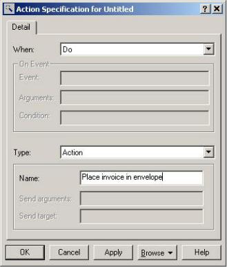
Enter the action's name, as shown in Figure 3.19.
99
Chapter 3: Business Modeling
Figure 3.19: Action specification window
8.
If the action was on an event, enter the event that triggers the action, any arguments to the event, and any guard conditions. A guard condition must be true for the action to occur.
9.
Click OK to close the action specification.
10.
Click OK to close the activity specification.
To add a business object:
1.
Select the Object toolbar button.
Note The Object button does not appear by default when you install Rose. You may need to customize the toolbar to see it.
2.
Click inside the diagram within the swimlane for the worker or unit responsible for performing the activity that will affect the object.
3.
Name the new object.
To draw transitions between activities:
1.
100
Chapter 3: Business Modeling
Select the State Transition toolbar button.
2.
Drag and drop from one activity to another.
To set a condition on the transition:
1.
Right−click the transition.
2.
Select the Open Specification option.
3.
Select the Detail tab.
4.
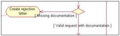
Type the condition in the Guard Condition field. When the condition is displayed on the diagram, it will be surrounded by square brackets to indicate that it is a guard condition, as shown in Figure 3.20. You can also type the guard condition directly on the transition by enclosing it in square brackets.
Figure 3.20: Guard conditions on transitions
To add a decision point:
1.
Select the Decision toolbar button.
2.
Click inside the diagram to place the decision.
3.
Draw two or more transitions from the decision, one for each decision possibility.
To add a synchronization:
1.
Select the Horizontal or Vertical Synchronization toolbar button.
2.
Click inside the diagram to place the synchronization.
3.
Draw two or more transitions from the synchronization, one to each activity that will occur simultaneously, as shown in Figure 3.21.
101