

- •Table of Contents
- •Mastering UML with Rational Rose 2002
- •Chapter 1: Introduction to UML
- •Encapsulation
- •Inheritance
- •Polymorphism
- •What Is Visual Modeling?
- •Systems of Graphical Notation
- •Booch Notation
- •Object Management Technology (OMT)
- •Unified Modeling Language (UML)
- •Understanding UML Diagrams
- •Business Use Case Diagrams
- •Use Case Diagrams
- •Activity Diagrams
- •Sequence Diagrams
- •Collaboration Diagrams
- •Class Diagrams
- •Statechart Diagrams
- •Component Diagrams
- •Deployment Diagrams
- •Visual Modeling and the Software Development Process
- •Inception
- •Elaboration
- •Construction
- •Transition
- •Summary
- •Chapter 2: A Tour of Rose
- •What Is Rose?
- •Getting Around in Rose
- •Parts of the Screen
- •Exploring Four Views in a Rose Model
- •Use Case View
- •Logical View
- •Component View
- •Deployment View
- •Working with Rose
- •Creating Models
- •Saving Models
- •Exporting and Importing Models
- •Publishing Models to the Web
- •Working with Controlled Units
- •Using the Model Integrator
- •Working with Notes
- •Working with Packages
- •Adding Files and URLs to Rose Model Elements
- •Adding and Deleting Diagrams
- •Setting Global Options
- •Working with Fonts
- •Working with Colors
- •Summary
- •Chapter 3: Business Modeling
- •Introduction to Business Modeling
- •Why Model the Business?
- •Do I Need to Do Business Modeling?
- •Business Modeling in an Iterative Process
- •Business Actors
- •Business Workers
- •Business Use Cases
- •Business Use Case Diagrams
- •Activity Diagrams
- •Business Entities
- •Organization Unit
- •Where Do I Start?
- •Identifying the Business Actors
- •Identifying the Business Workers
- •Identifying the Business Use Cases
- •Showing the Interactions
- •Documenting the Details
- •Creating Business Use Case Diagrams
- •Deleting Business Use Case Diagrams
- •The Use Case Diagram Toolbar
- •Adding Business Use Cases
- •Business Use Case Specifications
- •Assigning a Priority to a Business Use Case
- •Viewing Diagrams for a Business Use Case
- •Viewing Relationships for a Business Use Case
- •Working with Business Actors
- •Adding Business Actors
- •Adding Actor Specifications
- •Assigning an Actor Stereotype
- •Setting Business Actor Multiplicity
- •Viewing Relationships for a Business Actor
- •Working with Relationships
- •Association Relationship
- •Generalization Relationship
- •Working with Organization Units
- •Adding Organization Units
- •Deleting Organization Units
- •Activity Diagrams
- •Adding an Activity Diagram
- •Adding Details to an Activity Diagram
- •Summary
- •Chapter 4: Use Cases and Actors
- •Use Case Modeling Concepts
- •Actors
- •Use Cases
- •Traceability
- •Flow of Events
- •Relationships
- •Use Case Diagrams
- •Activity Diagrams
- •Activity
- •Start and End States
- •Objects and Object Flows
- •Transitions
- •Synchronization
- •Working with Use Cases in Rational Rose
- •The Use Case Diagram Toolbar
- •Creating Use Case Diagrams
- •Deleting Use Case Diagrams
- •Adding Use Cases
- •Deleting Use Cases
- •Use Case Specifications
- •Naming a Use Case
- •Viewing Participants of a Use Case
- •Assigning a Use Case Stereotype
- •Assigning a Priority to a Use Case
- •Creating an Abstract Use Case
- •Viewing Diagrams for a Use Case
- •Viewing Relationships for a Use Case
- •Working with Actors
- •Adding Actors
- •Deleting Actors
- •Actor Specifications
- •Naming Actors
- •Assigning an Actor Stereotype
- •Setting Actor Multiplicity
- •Creating an Abstract Actor
- •Viewing Relationships for an Actor
- •Viewing an Actor's Instances
- •Working with Relationships
- •Association Relationship
- •Includes Relationship
- •Extends Relationship
- •Generalization Relationship
- •Working with Activity Diagrams
- •The Activity Diagram Toolbar
- •Creating Activity Diagrams
- •Deleting Activity Diagrams
- •Exercise
- •Problem Statement
- •Create a Use Case Diagram
- •Summary
- •Chapter 5: Object Interaction
- •Interaction Diagrams
- •What Is an Object?
- •What Is a Class?
- •Where Do I Start?
- •Finding Objects
- •Finding the Actor
- •Using Interaction Diagrams
- •Sequence Diagrams
- •The Sequence Diagram Toolbar
- •Collaboration Diagrams
- •The Collaboration Diagram Toolbar
- •Working with Actors on an Interaction Diagram
- •Working with Objects
- •Adding Objects to an Interaction Diagram
- •Deleting Objects from an Interaction Diagram
- •Setting Object Specifications
- •Naming an Object
- •Mapping an Object to a Class
- •Setting Object Persistence
- •Using Multiple Instances of an Object
- •Working with Messages
- •Adding Messages to an Interaction Diagram
- •Adding Messages to a Sequence Diagram
- •Deleting Messages from a Sequence Diagram
- •Reordering Messages in a Sequence Diagram
- •Message Numbering in a Sequence Diagram
- •Viewing the Focus of Control in a Sequence Diagram
- •Adding Messages to a Collaboration Diagram
- •Deleting Messages from a Collaboration Diagram
- •Message Numbering in a Collaboration Diagram
- •Adding Data Flows to a Collaboration Diagram
- •Setting Message Specifications
- •Naming a Message
- •Mapping a Message to an Operation
- •Setting Message Synchronization Options
- •Setting Message Frequency
- •End of a Lifeline
- •Working with Scripts
- •Switching Between Sequence and Collaboration Diagrams
- •Exercise
- •Problem Statement
- •Create Interaction Diagrams
- •Summary
- •Chapter 6: Classes and Packages
- •Logical View of a Rose Model
- •Class Diagrams
- •What Is a Class?
- •Finding Classes
- •Creating Class Diagrams
- •Deleting Class Diagrams
- •Organizing Items on a Class Diagram
- •Using the Class Diagram Toolbar
- •Working with Classes
- •Adding Classes
- •Class Stereotypes
- •Analysis Stereotypes
- •Class Types
- •Interfaces
- •Web Modeling Stereotypes
- •Other Language Stereotypes
- •Class Specifications
- •Naming a Class
- •Setting Class Visibility
- •Setting Class Multiplicity
- •Setting Storage Requirements for a Class
- •Setting Class Persistence
- •Setting Class Concurrency
- •Creating an Abstract Class
- •Viewing Class Attributes
- •Viewing Class Operations
- •Viewing Class Relationships
- •Using Nested Classes
- •Viewing the Interaction Diagrams That Contain a Class
- •Setting Java Class Specifications
- •Setting CORBA Class Specifications
- •Working with Packages
- •Adding Packages
- •Deleting Packages
- •Exercise
- •Problem Statement
- •Creating a Class Diagram
- •Summary
- •Chapter 7: Attributes and Operations
- •Working with Attributes
- •Finding Attributes
- •Adding Attributes
- •Deleting Attributes
- •Setting Attribute Specifications
- •Setting the Attribute Containment
- •Making an Attribute Static
- •Specifying a Derived Attribute
- •Working with Operations
- •Finding Operations
- •Adding Operations
- •Deleting Operations
- •Setting Operation Specifications
- •Adding Arguments to an Operation
- •Specifying the Operation Protocol
- •Specifying the Operation Qualifications
- •Specifying the Operation Exceptions
- •Specifying the Operation Size
- •Specifying the Operation Time
- •Specifying the Operation Concurrency
- •Specifying the Operation Preconditions
- •Specifying the Operation Postconditions
- •Specifying the Operation Semantics
- •Displaying Attributes and Operations on Class Diagrams
- •Showing Attributes
- •Showing Operations
- •Showing Visibility
- •Showing Stereotypes
- •Mapping Operations to Messages
- •Mapping an Operation to a Message on an Interaction Diagram
- •Exercise
- •Problem Statement
- •Add Attributes and Operations
- •Summary
- •Chapter 8: Relationships
- •Relationships
- •Types of Relationships
- •Finding Relationships
- •Associations
- •Using Web Association Stereotypes
- •Creating Associations
- •Deleting Associations
- •Dependencies
- •Creating Dependencies
- •Deleting Dependencies
- •Package Dependencies
- •Creating Package Dependencies
- •Deleting Package Dependencies
- •Aggregations
- •Creating Aggregations
- •Deleting Aggregations
- •Generalizations
- •Creating Generalizations
- •Deleting Generalizations
- •Working with Relationships
- •Setting Multiplicity
- •Using Relationship Names
- •Using Stereotypes
- •Using Roles
- •Setting Export Control
- •Using Static Relationships
- •Using Friend Relationships
- •Setting Containment
- •Using Qualifiers
- •Using Link Elements
- •Using Constraints
- •Exercise
- •Problem Statement
- •Adding Relationships
- •Summary
- •Chapter 9: Object Behavior
- •Statechart Diagrams
- •Creating a Statechart Diagram
- •Adding States
- •Adding State Details
- •Adding Transitions
- •Adding Transition Details
- •Adding Special States
- •Using Nested States and State History
- •Exercise
- •Problem Statement
- •Create a Statechart Diagram
- •Summary
- •Chapter 10: Component View
- •What Is a Component?
- •Types of Components
- •Component Diagrams
- •Creating Component Diagrams
- •Adding Components
- •Adding Component Details
- •Adding Component Dependencies
- •Exercise
- •Problem Statement
- •Summary
- •Chapter 11: Deployment View
- •Deployment Diagrams
- •Opening the Deployment Diagram
- •Adding Processors
- •Adding Processor Details
- •Adding Devices
- •Adding Device Details
- •Adding Connections
- •Adding Connection Details
- •Adding Processes
- •Exercise
- •Problem Statement
- •Create Deployment Diagram
- •Summary
- •Chapter 12: Introduction to Code Generation and Reverse Engineering Using Rational Rose
- •Preparing for Code Generation
- •Step One: Check the Model
- •Step Two: Create Components
- •Step Three: Map Classes to Components
- •Step Five: Select a Class, Component, or Package
- •Step Six: Generate Code
- •What Gets Generated?
- •Introduction to Reverse Engineering Using Rational Rose
- •Model Elements Created During Reverse Engineering
- •Summary
- •Chapter 13: ANSI C++ and Visual C++ Code Generation and Reverse Engineering
- •Generating Code in ANSI C++ and Visual C++
- •Converting a C++ Model to an ANSI C++ Model
- •Class Properties
- •Attribute Properties
- •Operation Properties
- •Package (Class Category) Properties
- •Component (Module Specification) Properties
- •Role Properties
- •Generalization Properties
- •Class Model Assistant
- •Component Properties
- •Project Properties
- •Visual C++ and ATL Objects
- •Generated Code
- •Code Generated for Classes
- •Code Generated for Attributes
- •Code Generated for Operations
- •Visual C++ Code Generation
- •Reverse Engineering ANSI C++
- •Reverse Engineering Visual C++
- •Summary
- •Overview
- •Introduction to Rose J
- •Beginning a Java Project
- •Selecting a Java Framework
- •Linking to IBM VisualAge for Java
- •Linking to Microsoft Visual J++
- •Project Properties
- •Class Properties
- •Attribute Properties
- •Operation Properties
- •Module Properties
- •Role Properties
- •Generating Code
- •Generated Code
- •Classes
- •Attributes
- •Operations
- •Bidirectional Associations
- •Unidirectional Associations
- •Associations with a Multiplicity of One to Many
- •Associations with a Multiplicity of Many to Many
- •Reflexive Associations
- •Aggregations
- •Dependency Relationships
- •Generalization Relationships
- •Interfaces
- •Java Beans
- •Support for J2EE
- •EJBs
- •Servlets
- •JAR and WAR Files
- •Automated J2EE Deployment
- •Reverse Engineering
- •Summary
- •Starting a Visual Basic Project
- •Class Properties
- •Attribute Properties
- •Operation Properties
- •Module Specification Properties
- •Role Properties
- •Generalization Properties
- •Generated Code
- •Classes
- •Attributes
- •Operations
- •Bidirectional Associations
- •Unidirectional Associations
- •Associations with a Multiplicity of One to Many
- •Associations with a Multiplicity of Many to Many
- •Reflexive Associations
- •Aggregations
- •Dependency Relationships
- •Generalization Relationships
- •Reverse Engineering
- •Summary
- •Overview
- •Introduction to XML DTD
- •Elements
- •Attributes
- •Entities and Notations
- •Project Properties
- •Class Properties
- •Attribute Properties
- •Role Properties
- •Component Properties
- •Generating Code
- •Generated Code
- •Classes
- •Attributes
- •Reverse Engineering DTD
- •Summary
- •Project Properties
- •Class Properties
- •Attribute Properties
- •Operation Properties
- •Module Properties
- •Association (Role) Properties
- •Dependency Properties
- •Generated Code
- •Classes
- •Attributes
- •Operations
- •Bidirectional Associations
- •Unidirectional Associations
- •Associations with a Multiplicity of One to Many
- •Associations with a Multiplicity of Many to Many
- •Associations with Bounded Multiplicity
- •Reflexive Associations
- •Aggregations
- •Dependency Relationships
- •Generalization Relationships
- •Reverse Engineering CORBA Source Code
- •Summary
- •Chapter 18: Rose Data Modeler
- •Object Models and Data Models
- •Creating a Data Model
- •Logic in a Data Model
- •Adding a Database
- •Adding Tablespaces
- •Adding a Schema
- •Creating a Data Model Diagram
- •Creating Domain Packages and Domains
- •Adding Tables
- •Adding Columns
- •Setting a Primary Key
- •Adding Constraints
- •Adding Triggers
- •Adding Indexes
- •Adding Stored Procedures
- •Adding Relationships
- •Adding Referential Integrity Rules
- •Working with Views
- •Generating an Object Model from a Data Model
- •Generating a Data Model from an Object Model
- •Generating a Database from a Data Model
- •Updating an Existing Database
- •Reverse Engineering a Database
- •Summary
- •Chapter 19: Web Modeling
- •Modeling a Web Application
- •Web Class Stereotypes
- •Relationships
- •Reverse Engineering a Web Application
- •Generating Code for a Web Application
- •Summary
- •Appendix: Getting Started with UML
- •Building a Business Use Case Diagram
- •Building a Workflow (Activity) Diagram
- •Building a Use Case Diagram
- •Building an Interaction Diagram
- •Building a Class Diagram
- •Web Modeling
- •Adding Class Relationships
- •Building a Statechart Diagram
- •Building a Component Diagram
- •Building a Deployment Diagram
Chapter 3: Business Modeling
OR
1.
Select the use case on a Use Case diagram.
2.
Press Ctrl+B.
Assigning a Priority to a Business Use Case
To help you manage the project, you may want to prioritize the business use cases. You could use the priority, for example, to determine in what order the business use cases will be analyzed and documented. The Rose specifications window provides a field called Rank, which can be used to prioritize the business use cases. It does not set up a numbering scheme for you, but you can use letters, numbers, or any other way of prioritizing the use cases.
To assign a priority to a business use case:
1.
Right−click the business use case in the browser or on the Use Case diagram.
2.
Select Open Specification from the shortcut menu.
3.
On the General tab, enter the priority in the Rank field.
Viewing Diagrams for a Business Use Case
As you analyze a business use case, you may create a number of activity diagrams to document the workflow. Using the specification window or the browser, you can see a list of all of the diagrams for this particular business use case. Note that this list does not show you on which diagrams the use case resides; instead it shows you which diagrams contain some details for the use case.
To view the diagrams for a business use case:
1.
Right−click the business use case in the browser or on a Use Case diagram.
2.
Select Open Specification from the shortcut menu.
3.
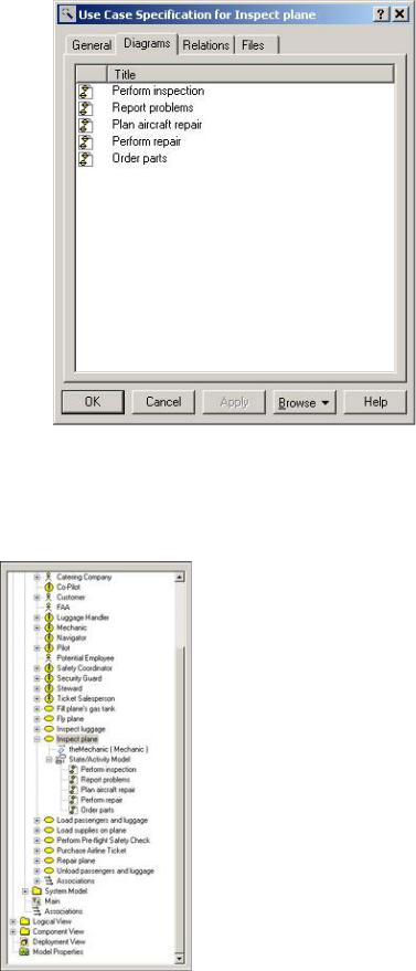
The diagrams will be listed on the Diagrams tab of the specification window, as shown in Figure 3.11. In this example, the use case has five activity diagrams.
83
Chapter 3: Business Modeling
Figure 3.11: Diagrams tab of a use case specification window
OR
Look through the browser. The diagrams for the use case will appear underneath the business use case in the browser, as shown in Figure 3.12.
Figure 3.12: Diagrams for a use case
84
Chapter 3: Business Modeling
To open a diagram for a use case:
Double−click the diagram name on the Diagrams tab of the use case specification window.
OR
Right−click the diagram name on the Diagrams tab of the use case specification window and select Open Diagram from the shortcut menu.
OR
Double−click the diagram in the browser.
To add a diagram to a use case:
1.
Right−click anywhere inside the Diagrams tab of the use case specification window.
2.
From the shortcut menu, select the type of diagram (Use Case, Sequence, Collaboration, Statechart, Activity, or Class) you want to add.
3.
Enter the name of the new diagram.
OR
1.
Right−click the use case in the browser.
2.
Select New → (Collaboration Diagram, Sequence Diagram, Class Diagram, Use Case Diagram, Statechart Diagram, Activity Diagram) from the shortcut menu.
3.
Enter the name of the new diagram.
To delete a diagram for a use case:
1.
Right−click the diagram name on the Diagrams tab of the use case specification window.
2.
Select Delete from the shortcut menu.
OR
1.
Right−click the diagram name in the browser.
2.
85
Chapter 3: Business Modeling
Select Delete from the shortcut menu.
Viewing Relationships for a Business Use Case
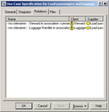
A relationship is a link between the business use case and a business actor or worker. It shows which business actor or worker initiates the business use case. As with diagrams, you can view the relationships for a particular business use case either through the specifications window or directly in the Rose browser. In the specifications window, the relationships are listed in the Relations tab, as shown in Figure 3.13.
Figure 3.13: Relations tab of a use case specification window
To view the relationships for a use case:
1.
Right−click the use case in the browser or on a Use Case diagram.
2.
Select Open Specification from the shortcut menu.
3.
The relationships will be listed on the Relations tab. The actor or worker who initiates the use case (or who is a client of the use case's functionality) will be listed in the Client column. The business use case itself (which supplies the functionality) is listed in the Supplier column.
OR
1.
Select the use case on a Use Case diagram.
2.
Select Report → Show Usage.
OR
Simply look at the hierarchy in the browser. The relationships for the business use case will be in the treeview below the use case itself.
86