

Chapter 9: Object Behavior
We've looked at classes and their relationships; we'll now examine the life of a single object. A given object can exist in one or more states. For example, an employee can be employed, fired, on probation, on leave, or retired. An Employee object may behave differently in each of these states.
In this chapter, we discuss Statechart diagrams, which include information about the various states in which an object can exist, how the object transitions from one state to another, and how the object behaves differently in each of the states.
∙
Creating a Statechart diagram
∙
Adding activities, entry actions, exit actions, events, and state histories to states
∙
Adding events, arguments, guard conditions, actions, and send events to transitions
∙
Adding start, stop, and nested states
Statechart Diagrams
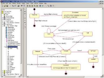
A Statechart diagram shows the life cycle of a single object, from the time that it is created until it is destroyed. These diagrams are a good way to model the dynamic behavior of a class. In a typical project, you do not create a Statechart diagram for every class. In fact, many projects do not use them at all. Figure 9.1 is an example of a Statechart diagram for our Flight class.
Figure 9.1: Statechart diagram for a Flight class
In this chapter, we discuss the different pieces of notation in this diagram. Briefly, however, we can read the diagram as follows:
A flight begins in a Tentative state. Someone reviews the schedule to determine whether or not to include the
341

Chapter 9: Object Behavior
flight. If the schedule is rejected, the flight is deleted and no further action can be taken. If the schedule is approved, the flight moves into a Scheduled status. The flight schedule is posted to the Internet, and as soon as it is 60 days or less before the flight, the flight becomes open. We can add and remove passengers from the flight, but as soon as the last seat is sold, the flight is full. If someone then cancels their reservation, the flight can become open again. Ten minutes before takeoff, the flight is closed for reservations. If the plane has not yet arrived, the flight is delayed until either the plane arrives or it has been four hours. After four hours, the flight is canceled. If the plane has arrived, but there are fewer than 50 people, the flight is canceled. If the flight is canceled, the airline will find an alternate flight for the passengers. If the plane does arrive, it takes off and lands, which is the conclusion of this particular flight.
If you have a class that has some significant dynamic behavior, it can be helpful to create a Statechart diagram for it. A class with significant dynamic behavior is one that can exist in many states. In our airline example, a flight may be scheduled, open, full, or canceled.
To decide whether a class has significant dynamic behavior, begin by looking at its attributes. Consider how an instance of the class might behave differently with different values in an attribute. If you have an attribute called Status, this can be a good indicator of various states. How does the object behave differently as different values are placed in this attribute?
You can also examine the relationships of a class. Look for any relationships with a zero in the multiplicity. Zeroes indicate that the relationship is optional. Does an instance of the class behave differently when the relationship does or does not exist? If it does, you may have multiple states. For example, let's look at a relationship between a person and a company. If there is a relationship, the person is in an employed state. If there is no relationship, the person may be fired or retired.
In Rose, no source code is generated from a Statechart diagram. These diagrams serve to document the dynamic behavior of a class so that developers and analysts will have a clear understanding of the behavior. The developers are ultimately responsible for implementing the logic outlined in the diagram. As with the other UML diagrams, Statechart diagrams give the team a chance to discuss and document the logic before it is coded.
Creating a Statechart Diagram
In Rose, you can create one or more Statechart diagrams per class. In the browser, the Statechart diagrams appear underneath the class. The Rose icon for a Statechart diagram in the browser is shown below:
To create a Statechart diagram:
1.
Right−click the desired class in the browser.
2.
Select New → Statechart Diagram from the pop−up menu.
Rose will create an entry under the class in the browser called State/Activity Model. Underneath this entry will be a new Statechart diagram called NewDiagram. You can create additional Statechart or activity diagrams for the class by right−clicking State/Activity Model in the browser and selecting New → Statechart Diagram or New → Activity Diagram.
342

Chapter 9: Object Behavior
Adding States
A state is one of the possible conditions in which an object may exist. You can examine two areas to determine the state of an object: the values of the attributes and the relationships to other objects. Consider the different values that can be placed in the attributes and the state of the object if a relationship does or does not exist. Our Flight class, for example, might have an attribute called NumPassengers. Consider how the flight behaves depending upon the value of NumPassengers. If there are 0 passengers, should the flight be able to leave at all? What if there are 500 scheduled passengers on a flight that holds 150? What if there are only 50? 10? 5? At what point does the flight go ahead, and at what point is it canceled?
We can also look at the attribute DepartureDate. If the departure date is three years in the future, do we let passengers reserve the flight? We might want to put the flight in a Scheduled status until it's a little closer to the departure date. On the other hand, we may want to open the flight immediately, even if it doesn't depart for three years. The business requirements will dictate the system behavior.
Examining attributes like these can help us determine what some of the states of the object might be. So far, we have states called Full, Open, and Scheduled. We may even want to include an Overbooked state if we can put 500 reservations on a 150−person flight.
We can also look at the relationships between the flight and other objects to look for states. If there is a relationship to a Schedule object, the flight has been scheduled. If there is no relationship to a Pilot object, we will put the flight into the Canceled state.
As with other Rose elements, you can add documentation to a state. However, because code is not generated from these diagrams, comments will not be inserted into generated code for state documentation.
In UML, a state is shown as a rounded rectangle:
To add a state:
1.
Select State from the toolbox toolbar.
2.
Click on the Statechart diagram where the state should appear.
OR
1.
Select Tools → Create → State.
2.
Click on the Statechart diagram where the state should appear.
To add documentation to a state:
1.
343
Chapter 9: Object Behavior
Double−click the desired state to open the state specification window.
2.
Select the General tab.
3.
Enter documentation in the Documentation field.
OR
1.
Select the desired state.
2.
Select Browse → Specification.
3.
Select the General tab.
4.
Enter documentation in the Documentation field.
Adding State Details
While an object is in a particular state, there may be some activity that it performs. A report may be generated, some calculation may occur, or an event may be sent to another object. For example, while a flight is in the Scheduled state, it may check the current date periodically to see when it is 60 days before the flight date. As soon as it is 60 days before, the flight will be moved to the Open state. In Rose, you can include this type of information in the model through the state specification window.
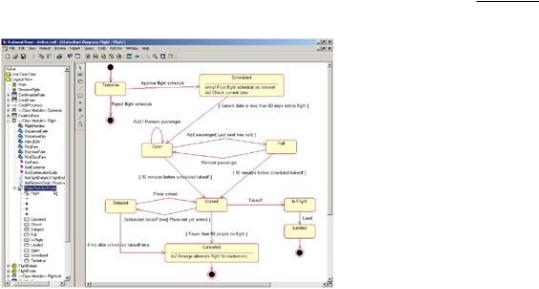
There are five types of information you can include for a state: an activity, an entry action, an exit action, an event, or a state history. Let's look at each of these in the context of our example. Figure 9.2 is the Statechart diagram for the Flight class.
Figure 9.2: Statechart diagram for Flight class
344

Chapter 9: Object Behavior
Activity
An activity is some behavior that an object carries out while it is in a particular state. For example, when an account is in the Closed state, the account holder's signature card is pulled. When a flight is in a Canceled state, the airline tries to find alternate flights for its customers. An activity is an interruptible behavior. It may run to completion while the object is in that state, or it may be interrupted by the object moving to another state.
An activity is shown inside the state itself, preceded by the word "do" and a slash.
Entry Action
An entry action is a behavior that occurs while the object is transitioning into the state. Using our flight example, as soon as a flight becomes scheduled, the system posts the schedule to the Internet. This happens while the flight is transitioning into the Scheduled state. Unlike an activity, an entry action is considered to be noninterruptible. While the posting of a schedule record for use on the Internet is technically interruptible, it happens very fast and the user does not have the ability to easily cancel the transaction while it is occurring. Therefore, it can be modeled as an action. There is a fine line between an action and an activity, but the distinguishing characteristic is whether or not it is interruptible.
An entry action is shown inside the state, preceded by the word "entry" and a slash.
Exit Action
An exit action is similar to an entry action. However, an exit action occurs as part of the transition out of a state. For example, when the plane lands and transitions out of the In Flight state, the system records the landing time. Like an entry action, an exit action is considered to be noninterruptible.
An exit action is shown inside the state, preceded by the word "exit" and a slash.
The behavior in an activity, entry action, or exit action can include sending an event to some other object. For example, if the flight is delayed for more than four hours, the flight object may need to send an event to a flight scheduler object, which will automatically reschedule the flight for another day. In this case, the activity, entry action, or exit action is preceded by a caret (^). The diagram would then read:
345
Chapter 9: Object Behavior
Do/ ^Target.Event(Arguments)
where Target is the object receiving the event, Event is the message being sent, and Arguments are parameters of the message being sent. In Rose, you can add all of these details to a send event.
An activity may also happen as a result of some event being received. For example, an account may be in the Open state. When some event occurs, the activity will be run.
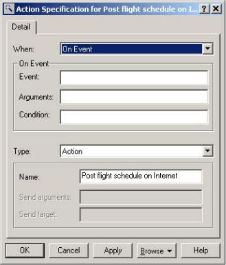
All of these items can be added to your Rose model through the action specification window, as shown in Figure 9.3.
Figure 9.3: Action specification window
To add an activity:
1.
Open the specification window for the desired state.
2.
Select the Action tab.
3.
Right−click the Actions box.
4.
Select Insert from the pop−up menu.
5.
Double−click the new action.
6. |
346 |
Chapter 9: Object Behavior
Enter the action in the Actions field.
7.
In the When box, select Do to make the new action an activity.
To add an entry action:
1.
Open the specification window for the desired state.
2.
Select the Action tab.
3.
Right−click the Actions box.
4.
Select Insert from the pop−up menu.
5.
Double−click the new action.
6.
Enter the action in the Actions field.
7.
In the When box, select On Entry.
To add an exit action:
1.
Open the specification window for the desired state.
2.
Select the Action tab.
3.
Right−click on the Actions box.
4.
Select Insert from the pop−up menu.
5.
Double−click the new action.
6.
Enter the action in the Actions field.
7.
In the When box, select On Exit.
347
Chapter 9: Object Behavior
To add an action that occurs on a specific event:
1.
Open the specification window for the desired state.
2.
Select the Action tab.
3.
Right−click the Actions box.
4.
Select Insert from the pop−up menu.
5.
Double−click the new action.
6.
Enter the action in the Actions field.
7.
In the When box, select On Event.
8.
Enter the event that triggers the action, along with any arguments of the event and any guard conditions that control whether or not the action should occur. If the guard condition is true, the action will occur on the event. If not, the action will not occur, even if the event happens.
To send an event:
1.
Open the specification window for the desired state.
2.
Select the Detail tab.
3.
Right−click the Actions box.
4.
Select Insert from the pop−up menu.
5.
Double−click the new action.
6.
Select Send Event as the type.
7.
Enter the event, arguments, and target in their respective fields.
348