- •Table of Contents
- •Mastering UML with Rational Rose 2002
- •Chapter 1: Introduction to UML
- •Encapsulation
- •Inheritance
- •Polymorphism
- •What Is Visual Modeling?
- •Systems of Graphical Notation
- •Booch Notation
- •Object Management Technology (OMT)
- •Unified Modeling Language (UML)
- •Understanding UML Diagrams
- •Business Use Case Diagrams
- •Use Case Diagrams
- •Activity Diagrams
- •Sequence Diagrams
- •Collaboration Diagrams
- •Class Diagrams
- •Statechart Diagrams
- •Component Diagrams
- •Deployment Diagrams
- •Visual Modeling and the Software Development Process
- •Inception
- •Elaboration
- •Construction
- •Transition
- •Summary
- •Chapter 2: A Tour of Rose
- •What Is Rose?
- •Getting Around in Rose
- •Parts of the Screen
- •Exploring Four Views in a Rose Model
- •Use Case View
- •Logical View
- •Component View
- •Deployment View
- •Working with Rose
- •Creating Models
- •Saving Models
- •Exporting and Importing Models
- •Publishing Models to the Web
- •Working with Controlled Units
- •Using the Model Integrator
- •Working with Notes
- •Working with Packages
- •Adding Files and URLs to Rose Model Elements
- •Adding and Deleting Diagrams
- •Setting Global Options
- •Working with Fonts
- •Working with Colors
- •Summary
- •Chapter 3: Business Modeling
- •Introduction to Business Modeling
- •Why Model the Business?
- •Do I Need to Do Business Modeling?
- •Business Modeling in an Iterative Process
- •Business Actors
- •Business Workers
- •Business Use Cases
- •Business Use Case Diagrams
- •Activity Diagrams
- •Business Entities
- •Organization Unit
- •Where Do I Start?
- •Identifying the Business Actors
- •Identifying the Business Workers
- •Identifying the Business Use Cases
- •Showing the Interactions
- •Documenting the Details
- •Creating Business Use Case Diagrams
- •Deleting Business Use Case Diagrams
- •The Use Case Diagram Toolbar
- •Adding Business Use Cases
- •Business Use Case Specifications
- •Assigning a Priority to a Business Use Case
- •Viewing Diagrams for a Business Use Case
- •Viewing Relationships for a Business Use Case
- •Working with Business Actors
- •Adding Business Actors
- •Adding Actor Specifications
- •Assigning an Actor Stereotype
- •Setting Business Actor Multiplicity
- •Viewing Relationships for a Business Actor
- •Working with Relationships
- •Association Relationship
- •Generalization Relationship
- •Working with Organization Units
- •Adding Organization Units
- •Deleting Organization Units
- •Activity Diagrams
- •Adding an Activity Diagram
- •Adding Details to an Activity Diagram
- •Summary
- •Chapter 4: Use Cases and Actors
- •Use Case Modeling Concepts
- •Actors
- •Use Cases
- •Traceability
- •Flow of Events
- •Relationships
- •Use Case Diagrams
- •Activity Diagrams
- •Activity
- •Start and End States
- •Objects and Object Flows
- •Transitions
- •Synchronization
- •Working with Use Cases in Rational Rose
- •The Use Case Diagram Toolbar
- •Creating Use Case Diagrams
- •Deleting Use Case Diagrams
- •Adding Use Cases
- •Deleting Use Cases
- •Use Case Specifications
- •Naming a Use Case
- •Viewing Participants of a Use Case
- •Assigning a Use Case Stereotype
- •Assigning a Priority to a Use Case
- •Creating an Abstract Use Case
- •Viewing Diagrams for a Use Case
- •Viewing Relationships for a Use Case
- •Working with Actors
- •Adding Actors
- •Deleting Actors
- •Actor Specifications
- •Naming Actors
- •Assigning an Actor Stereotype
- •Setting Actor Multiplicity
- •Creating an Abstract Actor
- •Viewing Relationships for an Actor
- •Viewing an Actor's Instances
- •Working with Relationships
- •Association Relationship
- •Includes Relationship
- •Extends Relationship
- •Generalization Relationship
- •Working with Activity Diagrams
- •The Activity Diagram Toolbar
- •Creating Activity Diagrams
- •Deleting Activity Diagrams
- •Exercise
- •Problem Statement
- •Create a Use Case Diagram
- •Summary
- •Chapter 5: Object Interaction
- •Interaction Diagrams
- •What Is an Object?
- •What Is a Class?
- •Where Do I Start?
- •Finding Objects
- •Finding the Actor
- •Using Interaction Diagrams
- •Sequence Diagrams
- •The Sequence Diagram Toolbar
- •Collaboration Diagrams
- •The Collaboration Diagram Toolbar
- •Working with Actors on an Interaction Diagram
- •Working with Objects
- •Adding Objects to an Interaction Diagram
- •Deleting Objects from an Interaction Diagram
- •Setting Object Specifications
- •Naming an Object
- •Mapping an Object to a Class
- •Setting Object Persistence
- •Using Multiple Instances of an Object
- •Working with Messages
- •Adding Messages to an Interaction Diagram
- •Adding Messages to a Sequence Diagram
- •Deleting Messages from a Sequence Diagram
- •Reordering Messages in a Sequence Diagram
- •Message Numbering in a Sequence Diagram
- •Viewing the Focus of Control in a Sequence Diagram
- •Adding Messages to a Collaboration Diagram
- •Deleting Messages from a Collaboration Diagram
- •Message Numbering in a Collaboration Diagram
- •Adding Data Flows to a Collaboration Diagram
- •Setting Message Specifications
- •Naming a Message
- •Mapping a Message to an Operation
- •Setting Message Synchronization Options
- •Setting Message Frequency
- •End of a Lifeline
- •Working with Scripts
- •Switching Between Sequence and Collaboration Diagrams
- •Exercise
- •Problem Statement
- •Create Interaction Diagrams
- •Summary
- •Chapter 6: Classes and Packages
- •Logical View of a Rose Model
- •Class Diagrams
- •What Is a Class?
- •Finding Classes
- •Creating Class Diagrams
- •Deleting Class Diagrams
- •Organizing Items on a Class Diagram
- •Using the Class Diagram Toolbar
- •Working with Classes
- •Adding Classes
- •Class Stereotypes
- •Analysis Stereotypes
- •Class Types
- •Interfaces
- •Web Modeling Stereotypes
- •Other Language Stereotypes
- •Class Specifications
- •Naming a Class
- •Setting Class Visibility
- •Setting Class Multiplicity
- •Setting Storage Requirements for a Class
- •Setting Class Persistence
- •Setting Class Concurrency
- •Creating an Abstract Class
- •Viewing Class Attributes
- •Viewing Class Operations
- •Viewing Class Relationships
- •Using Nested Classes
- •Viewing the Interaction Diagrams That Contain a Class
- •Setting Java Class Specifications
- •Setting CORBA Class Specifications
- •Working with Packages
- •Adding Packages
- •Deleting Packages
- •Exercise
- •Problem Statement
- •Creating a Class Diagram
- •Summary
- •Chapter 7: Attributes and Operations
- •Working with Attributes
- •Finding Attributes
- •Adding Attributes
- •Deleting Attributes
- •Setting Attribute Specifications
- •Setting the Attribute Containment
- •Making an Attribute Static
- •Specifying a Derived Attribute
- •Working with Operations
- •Finding Operations
- •Adding Operations
- •Deleting Operations
- •Setting Operation Specifications
- •Adding Arguments to an Operation
- •Specifying the Operation Protocol
- •Specifying the Operation Qualifications
- •Specifying the Operation Exceptions
- •Specifying the Operation Size
- •Specifying the Operation Time
- •Specifying the Operation Concurrency
- •Specifying the Operation Preconditions
- •Specifying the Operation Postconditions
- •Specifying the Operation Semantics
- •Displaying Attributes and Operations on Class Diagrams
- •Showing Attributes
- •Showing Operations
- •Showing Visibility
- •Showing Stereotypes
- •Mapping Operations to Messages
- •Mapping an Operation to a Message on an Interaction Diagram
- •Exercise
- •Problem Statement
- •Add Attributes and Operations
- •Summary
- •Chapter 8: Relationships
- •Relationships
- •Types of Relationships
- •Finding Relationships
- •Associations
- •Using Web Association Stereotypes
- •Creating Associations
- •Deleting Associations
- •Dependencies
- •Creating Dependencies
- •Deleting Dependencies
- •Package Dependencies
- •Creating Package Dependencies
- •Deleting Package Dependencies
- •Aggregations
- •Creating Aggregations
- •Deleting Aggregations
- •Generalizations
- •Creating Generalizations
- •Deleting Generalizations
- •Working with Relationships
- •Setting Multiplicity
- •Using Relationship Names
- •Using Stereotypes
- •Using Roles
- •Setting Export Control
- •Using Static Relationships
- •Using Friend Relationships
- •Setting Containment
- •Using Qualifiers
- •Using Link Elements
- •Using Constraints
- •Exercise
- •Problem Statement
- •Adding Relationships
- •Summary
- •Chapter 9: Object Behavior
- •Statechart Diagrams
- •Creating a Statechart Diagram
- •Adding States
- •Adding State Details
- •Adding Transitions
- •Adding Transition Details
- •Adding Special States
- •Using Nested States and State History
- •Exercise
- •Problem Statement
- •Create a Statechart Diagram
- •Summary
- •Chapter 10: Component View
- •What Is a Component?
- •Types of Components
- •Component Diagrams
- •Creating Component Diagrams
- •Adding Components
- •Adding Component Details
- •Adding Component Dependencies
- •Exercise
- •Problem Statement
- •Summary
- •Chapter 11: Deployment View
- •Deployment Diagrams
- •Opening the Deployment Diagram
- •Adding Processors
- •Adding Processor Details
- •Adding Devices
- •Adding Device Details
- •Adding Connections
- •Adding Connection Details
- •Adding Processes
- •Exercise
- •Problem Statement
- •Create Deployment Diagram
- •Summary
- •Chapter 12: Introduction to Code Generation and Reverse Engineering Using Rational Rose
- •Preparing for Code Generation
- •Step One: Check the Model
- •Step Two: Create Components
- •Step Three: Map Classes to Components
- •Step Five: Select a Class, Component, or Package
- •Step Six: Generate Code
- •What Gets Generated?
- •Introduction to Reverse Engineering Using Rational Rose
- •Model Elements Created During Reverse Engineering
- •Summary
- •Chapter 13: ANSI C++ and Visual C++ Code Generation and Reverse Engineering
- •Generating Code in ANSI C++ and Visual C++
- •Converting a C++ Model to an ANSI C++ Model
- •Class Properties
- •Attribute Properties
- •Operation Properties
- •Package (Class Category) Properties
- •Component (Module Specification) Properties
- •Role Properties
- •Generalization Properties
- •Class Model Assistant
- •Component Properties
- •Project Properties
- •Visual C++ and ATL Objects
- •Generated Code
- •Code Generated for Classes
- •Code Generated for Attributes
- •Code Generated for Operations
- •Visual C++ Code Generation
- •Reverse Engineering ANSI C++
- •Reverse Engineering Visual C++
- •Summary
- •Overview
- •Introduction to Rose J
- •Beginning a Java Project
- •Selecting a Java Framework
- •Linking to IBM VisualAge for Java
- •Linking to Microsoft Visual J++
- •Project Properties
- •Class Properties
- •Attribute Properties
- •Operation Properties
- •Module Properties
- •Role Properties
- •Generating Code
- •Generated Code
- •Classes
- •Attributes
- •Operations
- •Bidirectional Associations
- •Unidirectional Associations
- •Associations with a Multiplicity of One to Many
- •Associations with a Multiplicity of Many to Many
- •Reflexive Associations
- •Aggregations
- •Dependency Relationships
- •Generalization Relationships
- •Interfaces
- •Java Beans
- •Support for J2EE
- •EJBs
- •Servlets
- •JAR and WAR Files
- •Automated J2EE Deployment
- •Reverse Engineering
- •Summary
- •Starting a Visual Basic Project
- •Class Properties
- •Attribute Properties
- •Operation Properties
- •Module Specification Properties
- •Role Properties
- •Generalization Properties
- •Generated Code
- •Classes
- •Attributes
- •Operations
- •Bidirectional Associations
- •Unidirectional Associations
- •Associations with a Multiplicity of One to Many
- •Associations with a Multiplicity of Many to Many
- •Reflexive Associations
- •Aggregations
- •Dependency Relationships
- •Generalization Relationships
- •Reverse Engineering
- •Summary
- •Overview
- •Introduction to XML DTD
- •Elements
- •Attributes
- •Entities and Notations
- •Project Properties
- •Class Properties
- •Attribute Properties
- •Role Properties
- •Component Properties
- •Generating Code
- •Generated Code
- •Classes
- •Attributes
- •Reverse Engineering DTD
- •Summary
- •Project Properties
- •Class Properties
- •Attribute Properties
- •Operation Properties
- •Module Properties
- •Association (Role) Properties
- •Dependency Properties
- •Generated Code
- •Classes
- •Attributes
- •Operations
- •Bidirectional Associations
- •Unidirectional Associations
- •Associations with a Multiplicity of One to Many
- •Associations with a Multiplicity of Many to Many
- •Associations with Bounded Multiplicity
- •Reflexive Associations
- •Aggregations
- •Dependency Relationships
- •Generalization Relationships
- •Reverse Engineering CORBA Source Code
- •Summary
- •Chapter 18: Rose Data Modeler
- •Object Models and Data Models
- •Creating a Data Model
- •Logic in a Data Model
- •Adding a Database
- •Adding Tablespaces
- •Adding a Schema
- •Creating a Data Model Diagram
- •Creating Domain Packages and Domains
- •Adding Tables
- •Adding Columns
- •Setting a Primary Key
- •Adding Constraints
- •Adding Triggers
- •Adding Indexes
- •Adding Stored Procedures
- •Adding Relationships
- •Adding Referential Integrity Rules
- •Working with Views
- •Generating an Object Model from a Data Model
- •Generating a Data Model from an Object Model
- •Generating a Database from a Data Model
- •Updating an Existing Database
- •Reverse Engineering a Database
- •Summary
- •Chapter 19: Web Modeling
- •Modeling a Web Application
- •Web Class Stereotypes
- •Relationships
- •Reverse Engineering a Web Application
- •Generating Code for a Web Application
- •Summary
- •Appendix: Getting Started with UML
- •Building a Business Use Case Diagram
- •Building a Workflow (Activity) Diagram
- •Building a Use Case Diagram
- •Building an Interaction Diagram
- •Building a Class Diagram
- •Web Modeling
- •Adding Class Relationships
- •Building a Statechart Diagram
- •Building a Component Diagram
- •Building a Deployment Diagram
Chapter 8: Relationships
To delete a generalization from the model:
1.
Select the desired generalization.
2.
Press Ctrl+D.
OR
1.
Select the desired generalization.
2.
Select Edit → Delete from Model.
OR
1.
Open the specification window for either class participating in the relationship.
2.
Select the Relations tab.
3.
Right−click the relationship.
4.
Select Delete from the shortcut menu.
Working with Relationships
In this section, we'll take a look at the detailed specifications of the relationships in Rose. In your model, you can add things like association names, role names, and qualifiers to specify why the relationship exists.
Before you generate code, you should specify the relationship multiplicity; otherwise Rose will provide a default. Most of the other specifications we present in this section, however, are optional. Rose will notify you if a required specification has not been set when you attempt to generate code.
Setting Multiplicity
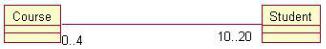
Multiplicity indicates how many instances of one class are related to a single instance of another class at a given point in time. For example, if we're looking at a course registration system for a university, we may have classes called Course and Student. There is a relationship between them; courses have students and students have courses. The questions answered by the multiplicity are "How many courses can a student take at one time?" and "How many students can be enrolled in a single course at one time?"
324
Chapter 8: Relationships
Because the multiplicity answers both questions, the multiplicity indicators are included at both ends of the relationship. In the course registration example, we decide that each student can be enrolled in 0 to 4 classes, and each course can have 10 to 20 students. On a Class diagram, this would be shown as in Figure 8.19.
Figure 8.19: Relationship multiplicity
In this figure, the 0..4 means that each student can be enrolled in 0 through 4 classes, and the 10..20 means that each class can have 10 to 20 students.
Keep in mind that the multiplicity settings will let you know whether the relationship is optional. In our example above, a student can take from 0 to 4 courses at any one time. Therefore, someone is still considered a student if they have taken a semester off. Had the multiplicity been 1..4 instead, every student would be required to take at least 1 course per semester. The multiplicity, therefore, implements business rules such as "every student must take at least one course per semester."
Typically, multiplicity between forms, screens, or windows will be 0..1 on each side of the relationship. Although this doesn't always hold true, this multiplicity would indicate that each form can exist independently of the other.
UML notations for multiplicity are as follows:
Multiplicity |
Meaning |
* |
Many |
0 |
Zero |
1 |
One |
0..* |
Zero or more |
1..* |
One or more |
0..1 |
Zero or one |
1..1 |
Exactly one |
Or, you can enter your own multiplicity, using one of the following formats: |
|
|
|
Format |
Meaning |
<number> |
Exactly <number> |
<number 1>..<number 2> |
Between <number 1> and <number 2> |
<number>..n |
<number> or more |
<number 1>,<number 2> |
<number 1> or <number 2> |
<number 1>, <number 2>..<number 3> |
Exactly <number 1> or between <number 2> and |
|
<number 3> |
<number 1>..<number 2>,<number 3>..<number 4> |
Between <number 1> and <number 2> or between |
|
<number 3> and <number 4> |
To set relationship multiplicity: |
|
1.
Right−click the desired relationship on one end.
2.
325
Chapter 8: Relationships
Select Multiplicity from the shortcut menu.
3.
Select the desired multiplicity.
4.
Repeat steps 1–3 for the other end of the relationship.
OR
1.
Open the desired relationship's specification window.
2.
Select the Role Detail tab for one end.
3.
Change the multiplicity using the cardinality field.
4.
Repeat steps 1–3 for the other end of the relationship.
Using Relationship Names
Relationships can be refined using relationship names or role names. A relationship name is usually a verb or verb phrase that describes why the relationship exists. For example, we may have an association between a Person class and a Company class. From this, though, we might ask these questions: Why does this relationship exist? Is the person a customer of the company, an employee, or an owner? We can name the relationship employs to specify why the relationship exists. Figure 8.20 is an example of a relationship name.
Figure 8.20: Relationship name
Relationship names are optional, and are typically used only when the reason for the relationship is not obvious. Relationship names are shown along the relationship line.
In Rose, you can also set the relationship direction. In the example above, we can say that the company employs the person, but can't say that the person employs the company. You can set the name direction in the relationship specification window.
To set the relationship name:
1.
Select the desired relationship.
2.
Type in the desired name.
OR
1. |
326 |
Chapter 8: Relationships
Open the desired relationship's specification window.
2.
Select the General tab.
3.
Enter the name in the Name field.
To set the name direction:
1.
Open the desired relationship's specification window.
2.
Select the Detail tab.
3.
Set the name direction using the Name Direction field.
Using Stereotypes
Like other model elements, you can assign a stereotype to a relationship. Stereotypes are used to classify relationships. In particular, when modeling web applications, you may want to set the stereotypes of the association relationships. As we discussed earlier in this chapter, there are four stereotypes in the Rose Web Modeler add−in: a link relationship, a submit relationship, a build relationship, and a redirect relationship. A link relationship is used to show one page that contains a hyperlink to another. A submit relationship shows a form submitting information to a server page. A build relationship is used to show a server page building a client page. Finally, a redirect relationship shows how processing control is passed from one page to another.
Stereotypes are shown along the association line and are enclosed in double angle brackets (<<>>). To set the relationship stereotype, you can use the General tab of the relationship specification window, as shown in Figure 8.21.
327