- •Table of Contents
- •Mastering UML with Rational Rose 2002
- •Chapter 1: Introduction to UML
- •Encapsulation
- •Inheritance
- •Polymorphism
- •What Is Visual Modeling?
- •Systems of Graphical Notation
- •Booch Notation
- •Object Management Technology (OMT)
- •Unified Modeling Language (UML)
- •Understanding UML Diagrams
- •Business Use Case Diagrams
- •Use Case Diagrams
- •Activity Diagrams
- •Sequence Diagrams
- •Collaboration Diagrams
- •Class Diagrams
- •Statechart Diagrams
- •Component Diagrams
- •Deployment Diagrams
- •Visual Modeling and the Software Development Process
- •Inception
- •Elaboration
- •Construction
- •Transition
- •Summary
- •Chapter 2: A Tour of Rose
- •What Is Rose?
- •Getting Around in Rose
- •Parts of the Screen
- •Exploring Four Views in a Rose Model
- •Use Case View
- •Logical View
- •Component View
- •Deployment View
- •Working with Rose
- •Creating Models
- •Saving Models
- •Exporting and Importing Models
- •Publishing Models to the Web
- •Working with Controlled Units
- •Using the Model Integrator
- •Working with Notes
- •Working with Packages
- •Adding Files and URLs to Rose Model Elements
- •Adding and Deleting Diagrams
- •Setting Global Options
- •Working with Fonts
- •Working with Colors
- •Summary
- •Chapter 3: Business Modeling
- •Introduction to Business Modeling
- •Why Model the Business?
- •Do I Need to Do Business Modeling?
- •Business Modeling in an Iterative Process
- •Business Actors
- •Business Workers
- •Business Use Cases
- •Business Use Case Diagrams
- •Activity Diagrams
- •Business Entities
- •Organization Unit
- •Where Do I Start?
- •Identifying the Business Actors
- •Identifying the Business Workers
- •Identifying the Business Use Cases
- •Showing the Interactions
- •Documenting the Details
- •Creating Business Use Case Diagrams
- •Deleting Business Use Case Diagrams
- •The Use Case Diagram Toolbar
- •Adding Business Use Cases
- •Business Use Case Specifications
- •Assigning a Priority to a Business Use Case
- •Viewing Diagrams for a Business Use Case
- •Viewing Relationships for a Business Use Case
- •Working with Business Actors
- •Adding Business Actors
- •Adding Actor Specifications
- •Assigning an Actor Stereotype
- •Setting Business Actor Multiplicity
- •Viewing Relationships for a Business Actor
- •Working with Relationships
- •Association Relationship
- •Generalization Relationship
- •Working with Organization Units
- •Adding Organization Units
- •Deleting Organization Units
- •Activity Diagrams
- •Adding an Activity Diagram
- •Adding Details to an Activity Diagram
- •Summary
- •Chapter 4: Use Cases and Actors
- •Use Case Modeling Concepts
- •Actors
- •Use Cases
- •Traceability
- •Flow of Events
- •Relationships
- •Use Case Diagrams
- •Activity Diagrams
- •Activity
- •Start and End States
- •Objects and Object Flows
- •Transitions
- •Synchronization
- •Working with Use Cases in Rational Rose
- •The Use Case Diagram Toolbar
- •Creating Use Case Diagrams
- •Deleting Use Case Diagrams
- •Adding Use Cases
- •Deleting Use Cases
- •Use Case Specifications
- •Naming a Use Case
- •Viewing Participants of a Use Case
- •Assigning a Use Case Stereotype
- •Assigning a Priority to a Use Case
- •Creating an Abstract Use Case
- •Viewing Diagrams for a Use Case
- •Viewing Relationships for a Use Case
- •Working with Actors
- •Adding Actors
- •Deleting Actors
- •Actor Specifications
- •Naming Actors
- •Assigning an Actor Stereotype
- •Setting Actor Multiplicity
- •Creating an Abstract Actor
- •Viewing Relationships for an Actor
- •Viewing an Actor's Instances
- •Working with Relationships
- •Association Relationship
- •Includes Relationship
- •Extends Relationship
- •Generalization Relationship
- •Working with Activity Diagrams
- •The Activity Diagram Toolbar
- •Creating Activity Diagrams
- •Deleting Activity Diagrams
- •Exercise
- •Problem Statement
- •Create a Use Case Diagram
- •Summary
- •Chapter 5: Object Interaction
- •Interaction Diagrams
- •What Is an Object?
- •What Is a Class?
- •Where Do I Start?
- •Finding Objects
- •Finding the Actor
- •Using Interaction Diagrams
- •Sequence Diagrams
- •The Sequence Diagram Toolbar
- •Collaboration Diagrams
- •The Collaboration Diagram Toolbar
- •Working with Actors on an Interaction Diagram
- •Working with Objects
- •Adding Objects to an Interaction Diagram
- •Deleting Objects from an Interaction Diagram
- •Setting Object Specifications
- •Naming an Object
- •Mapping an Object to a Class
- •Setting Object Persistence
- •Using Multiple Instances of an Object
- •Working with Messages
- •Adding Messages to an Interaction Diagram
- •Adding Messages to a Sequence Diagram
- •Deleting Messages from a Sequence Diagram
- •Reordering Messages in a Sequence Diagram
- •Message Numbering in a Sequence Diagram
- •Viewing the Focus of Control in a Sequence Diagram
- •Adding Messages to a Collaboration Diagram
- •Deleting Messages from a Collaboration Diagram
- •Message Numbering in a Collaboration Diagram
- •Adding Data Flows to a Collaboration Diagram
- •Setting Message Specifications
- •Naming a Message
- •Mapping a Message to an Operation
- •Setting Message Synchronization Options
- •Setting Message Frequency
- •End of a Lifeline
- •Working with Scripts
- •Switching Between Sequence and Collaboration Diagrams
- •Exercise
- •Problem Statement
- •Create Interaction Diagrams
- •Summary
- •Chapter 6: Classes and Packages
- •Logical View of a Rose Model
- •Class Diagrams
- •What Is a Class?
- •Finding Classes
- •Creating Class Diagrams
- •Deleting Class Diagrams
- •Organizing Items on a Class Diagram
- •Using the Class Diagram Toolbar
- •Working with Classes
- •Adding Classes
- •Class Stereotypes
- •Analysis Stereotypes
- •Class Types
- •Interfaces
- •Web Modeling Stereotypes
- •Other Language Stereotypes
- •Class Specifications
- •Naming a Class
- •Setting Class Visibility
- •Setting Class Multiplicity
- •Setting Storage Requirements for a Class
- •Setting Class Persistence
- •Setting Class Concurrency
- •Creating an Abstract Class
- •Viewing Class Attributes
- •Viewing Class Operations
- •Viewing Class Relationships
- •Using Nested Classes
- •Viewing the Interaction Diagrams That Contain a Class
- •Setting Java Class Specifications
- •Setting CORBA Class Specifications
- •Working with Packages
- •Adding Packages
- •Deleting Packages
- •Exercise
- •Problem Statement
- •Creating a Class Diagram
- •Summary
- •Chapter 7: Attributes and Operations
- •Working with Attributes
- •Finding Attributes
- •Adding Attributes
- •Deleting Attributes
- •Setting Attribute Specifications
- •Setting the Attribute Containment
- •Making an Attribute Static
- •Specifying a Derived Attribute
- •Working with Operations
- •Finding Operations
- •Adding Operations
- •Deleting Operations
- •Setting Operation Specifications
- •Adding Arguments to an Operation
- •Specifying the Operation Protocol
- •Specifying the Operation Qualifications
- •Specifying the Operation Exceptions
- •Specifying the Operation Size
- •Specifying the Operation Time
- •Specifying the Operation Concurrency
- •Specifying the Operation Preconditions
- •Specifying the Operation Postconditions
- •Specifying the Operation Semantics
- •Displaying Attributes and Operations on Class Diagrams
- •Showing Attributes
- •Showing Operations
- •Showing Visibility
- •Showing Stereotypes
- •Mapping Operations to Messages
- •Mapping an Operation to a Message on an Interaction Diagram
- •Exercise
- •Problem Statement
- •Add Attributes and Operations
- •Summary
- •Chapter 8: Relationships
- •Relationships
- •Types of Relationships
- •Finding Relationships
- •Associations
- •Using Web Association Stereotypes
- •Creating Associations
- •Deleting Associations
- •Dependencies
- •Creating Dependencies
- •Deleting Dependencies
- •Package Dependencies
- •Creating Package Dependencies
- •Deleting Package Dependencies
- •Aggregations
- •Creating Aggregations
- •Deleting Aggregations
- •Generalizations
- •Creating Generalizations
- •Deleting Generalizations
- •Working with Relationships
- •Setting Multiplicity
- •Using Relationship Names
- •Using Stereotypes
- •Using Roles
- •Setting Export Control
- •Using Static Relationships
- •Using Friend Relationships
- •Setting Containment
- •Using Qualifiers
- •Using Link Elements
- •Using Constraints
- •Exercise
- •Problem Statement
- •Adding Relationships
- •Summary
- •Chapter 9: Object Behavior
- •Statechart Diagrams
- •Creating a Statechart Diagram
- •Adding States
- •Adding State Details
- •Adding Transitions
- •Adding Transition Details
- •Adding Special States
- •Using Nested States and State History
- •Exercise
- •Problem Statement
- •Create a Statechart Diagram
- •Summary
- •Chapter 10: Component View
- •What Is a Component?
- •Types of Components
- •Component Diagrams
- •Creating Component Diagrams
- •Adding Components
- •Adding Component Details
- •Adding Component Dependencies
- •Exercise
- •Problem Statement
- •Summary
- •Chapter 11: Deployment View
- •Deployment Diagrams
- •Opening the Deployment Diagram
- •Adding Processors
- •Adding Processor Details
- •Adding Devices
- •Adding Device Details
- •Adding Connections
- •Adding Connection Details
- •Adding Processes
- •Exercise
- •Problem Statement
- •Create Deployment Diagram
- •Summary
- •Chapter 12: Introduction to Code Generation and Reverse Engineering Using Rational Rose
- •Preparing for Code Generation
- •Step One: Check the Model
- •Step Two: Create Components
- •Step Three: Map Classes to Components
- •Step Five: Select a Class, Component, or Package
- •Step Six: Generate Code
- •What Gets Generated?
- •Introduction to Reverse Engineering Using Rational Rose
- •Model Elements Created During Reverse Engineering
- •Summary
- •Chapter 13: ANSI C++ and Visual C++ Code Generation and Reverse Engineering
- •Generating Code in ANSI C++ and Visual C++
- •Converting a C++ Model to an ANSI C++ Model
- •Class Properties
- •Attribute Properties
- •Operation Properties
- •Package (Class Category) Properties
- •Component (Module Specification) Properties
- •Role Properties
- •Generalization Properties
- •Class Model Assistant
- •Component Properties
- •Project Properties
- •Visual C++ and ATL Objects
- •Generated Code
- •Code Generated for Classes
- •Code Generated for Attributes
- •Code Generated for Operations
- •Visual C++ Code Generation
- •Reverse Engineering ANSI C++
- •Reverse Engineering Visual C++
- •Summary
- •Overview
- •Introduction to Rose J
- •Beginning a Java Project
- •Selecting a Java Framework
- •Linking to IBM VisualAge for Java
- •Linking to Microsoft Visual J++
- •Project Properties
- •Class Properties
- •Attribute Properties
- •Operation Properties
- •Module Properties
- •Role Properties
- •Generating Code
- •Generated Code
- •Classes
- •Attributes
- •Operations
- •Bidirectional Associations
- •Unidirectional Associations
- •Associations with a Multiplicity of One to Many
- •Associations with a Multiplicity of Many to Many
- •Reflexive Associations
- •Aggregations
- •Dependency Relationships
- •Generalization Relationships
- •Interfaces
- •Java Beans
- •Support for J2EE
- •EJBs
- •Servlets
- •JAR and WAR Files
- •Automated J2EE Deployment
- •Reverse Engineering
- •Summary
- •Starting a Visual Basic Project
- •Class Properties
- •Attribute Properties
- •Operation Properties
- •Module Specification Properties
- •Role Properties
- •Generalization Properties
- •Generated Code
- •Classes
- •Attributes
- •Operations
- •Bidirectional Associations
- •Unidirectional Associations
- •Associations with a Multiplicity of One to Many
- •Associations with a Multiplicity of Many to Many
- •Reflexive Associations
- •Aggregations
- •Dependency Relationships
- •Generalization Relationships
- •Reverse Engineering
- •Summary
- •Overview
- •Introduction to XML DTD
- •Elements
- •Attributes
- •Entities and Notations
- •Project Properties
- •Class Properties
- •Attribute Properties
- •Role Properties
- •Component Properties
- •Generating Code
- •Generated Code
- •Classes
- •Attributes
- •Reverse Engineering DTD
- •Summary
- •Project Properties
- •Class Properties
- •Attribute Properties
- •Operation Properties
- •Module Properties
- •Association (Role) Properties
- •Dependency Properties
- •Generated Code
- •Classes
- •Attributes
- •Operations
- •Bidirectional Associations
- •Unidirectional Associations
- •Associations with a Multiplicity of One to Many
- •Associations with a Multiplicity of Many to Many
- •Associations with Bounded Multiplicity
- •Reflexive Associations
- •Aggregations
- •Dependency Relationships
- •Generalization Relationships
- •Reverse Engineering CORBA Source Code
- •Summary
- •Chapter 18: Rose Data Modeler
- •Object Models and Data Models
- •Creating a Data Model
- •Logic in a Data Model
- •Adding a Database
- •Adding Tablespaces
- •Adding a Schema
- •Creating a Data Model Diagram
- •Creating Domain Packages and Domains
- •Adding Tables
- •Adding Columns
- •Setting a Primary Key
- •Adding Constraints
- •Adding Triggers
- •Adding Indexes
- •Adding Stored Procedures
- •Adding Relationships
- •Adding Referential Integrity Rules
- •Working with Views
- •Generating an Object Model from a Data Model
- •Generating a Data Model from an Object Model
- •Generating a Database from a Data Model
- •Updating an Existing Database
- •Reverse Engineering a Database
- •Summary
- •Chapter 19: Web Modeling
- •Modeling a Web Application
- •Web Class Stereotypes
- •Relationships
- •Reverse Engineering a Web Application
- •Generating Code for a Web Application
- •Summary
- •Appendix: Getting Started with UML
- •Building a Business Use Case Diagram
- •Building a Workflow (Activity) Diagram
- •Building a Use Case Diagram
- •Building an Interaction Diagram
- •Building a Class Diagram
- •Web Modeling
- •Adding Class Relationships
- •Building a Statechart Diagram
- •Building a Component Diagram
- •Building a Deployment Diagram
Chapter 1: Introduction to UML
The pace of business is getting faster and faster, with a greater need to compete and sustain a market. In this age of e−commerce, e−business, e−tailing, and other e's, "traditional" system development just doesn't cut it anymore. Systems now must be developed in "Internet time." Also, this faster pace has increased the need for flexible systems. Before, a user could send a request to the data−processing center and wait two years for a change. Now a user sends a request for change to the IT department and demands it in two weeks! Six−week development cycles, demanding managers, demanding users, and even the concept of XP (extreme programming) drive this point: System changes must happen fast!
This is where the Unified Modeling Language (UML) enters the picture. UML is the industry−standard modeling notation for object−oriented systems, and is the premiere platform for rapid application development. In this chapter, we describe how UML came into being, introduce the concepts of object−oriented programming, and show you how to use UML to structure your applications.
∙
Learning about the object−oriented paradigm and visual modeling
∙
Exploring types of graphical notation
∙
Looking at types of UML diagrams
∙
Developing software using visual modeling
Introduction to the Object−Oriented Paradigm
Structured programming was the mainstream in the earlier days of software engineering. Programmers began developing standard blocks of code to perform operations like printing, and then copied and pasted that code into every application they wrote. While this reduced the development time for new applications, it was difficult if a change was needed in that block of code, because the developer had to make the change everywhere that code had been copied. Structured programming presented some challenges for which object−oriented programming was designed to solve.
With object−oriented programming, developers create blocks of code, called objects. These objects are then used by the various applications. Should one of the objects require modification, a developer needs to make the change only once. Companies are rushing out to adopt this technology and integrate it into their existing applications. In fact, most applications being developed today are object−oriented. Some languages, such as Java, require an object−oriented structure. But what does it mean?
The object−oriented paradigm is a different way of viewing applications. With the object−oriented approach, you divide an application into many small chunks, or objects, that are fairly independent of one another. You can then build the application by piecing all of these objects together. Think of it as building a castle out of blocks. The first step is to make or buy some basic objects, the different types of blocks. Once you have these building blocks, you can put them together to make your castle. Once you build or buy some basic objects in the computer world, you can simply put them together to create new applications.
4
Chapter 1: Introduction to UML
In the world of structured programming, to create a form with a list box, for example, you would need to write voluminous code: the code to create the form itself, the code to create and populate the list box, and the code to create an OK button that will accept the value in the list box. With object−oriented programming, on the other hand, you simply need to use three (typically prebuilt) objects: a form, a list box, and an OK button. The exercise of coding used to be along the lines of "create from scratch, but copy whatever you can find from old programs to save some time." The newer paradigm is "put together a bunch of objects, and then just focus on what's unique to this particular application."
One of the primary advantages of the object−oriented paradigm is the ability to build components once and then use them over and over again. Just as you can reuse a toy building block in a castle or a house, you can reuse a basic piece of object−oriented design and code in an accounting system, an inventory system, or an order−processing system.
So, how is this object−oriented paradigm different from the traditional approach to development? Traditionally, the approach to development has been to concern ourselves with the information that the system will maintain. With this approach, we ask the users what information they will need, design databases to hold the information, provide screens to input the information, and print reports to display the information. In other words, we focus on the information and pay less attention to what is done with the information or the behavior of the system. This approach is called data−centric and has been used to create thousands of systems over the years.
Data−centric modeling is great for database design and capturing information, but taking this approach when designing business applications presents some problems. One major challenge is that the requirements for the system will change over time. A system that is data−centric can handle a change to the database very easily, but a change to the business rules or to the behavior of the system is not so easy to implement.
The object−oriented paradigm has been developed in response to this problem. With the object−oriented approach, we focus on both information and behavior. Accordingly, we now can develop systems that are resilient and flexible to changes in information and/or behavior.
The benefit of flexibility can be realized only by designing an object−oriented system well. This requires knowledge of some principles of object orientation: encapsulation, inheritance, and polymorphism.
Encapsulation
In object−oriented systems, we combine a piece of information with the specific behavior that acts upon that information. Then we package these into an object. This is referred to as encapsulation. Another way to look at encapsulation is that we divide the application into small parts of related functionality. For example, we have information relating to a bank account, such as the account number, balance, customer name, address, account type, interest rate, and opening date. We also have behavior for a bank account: open, close, deposit, withdraw, change type, change customer, and change address. We encapsulate this information and behavior together into an account object. As a result, any changes to the banking system regarding accounts can simply be implemented in the account object. It works like a one−stop shop for all account information and behavior.
Another benefit of encapsulation is that it limits the effects of changes to the system. Think of a system as a body of water and the requirement change as a big rock. You drop the rock into the water and—SPLASH!—big waves are created in all directions. They travel throughout the lake, bounce off the shore, reverberate, and collide with other waves. In fact, some of the water may even splash over the shore and out of the lake. In other words, the rock hitting the water caused a huge ripple effect. But if we encapsulate our lake by dividing it into smaller bodies of water with barriers between them, then the requirement change hits the system—SPLASH! As before, waves are created in all directions. But the waves
5
Chapter 1: Introduction to UML
can only go as far as one of the barriers, and then they stop. So, by encapsulating the lake, we have limited the ripple effect of dropping the rock in, as shown in Figure 1.1.
Figure 1.1: Encapsulation: Lake model
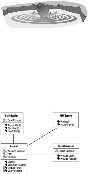
Let's apply this idea of encapsulation to the banking system. Recently, the bank management decided that if the customer has a credit account at the bank, the credit account could be used as an overdraft for their checking account. In a nonencapsulated system, we begin with a shotgun approach to impact analysis. Basically, we do not know where all of the uses of withdraw functionality are in the system, so we have to look everywhere. When we find it, we have to make some changes to incorporate this new requirement. If we're really good, we probably found about 80 percent of the uses of withdraw within the system. With an encapsulated system, we do not need to use the shotgun approach to analysis. We look at a model of our system and simply find where the withdrawal behavior was encapsulated. After locating the functionality in the account, we make our requirement change once, only in that object, and our task is complete! As you can see in Figure 1.2, only the Account class needs to change.
A concept similar to encapsulation is information hiding. Information hiding is the ability to hide the murky details of an object from the outside world. To an object, the outside world means anything outside of itself, even though that outside world includes the rest of the system. Information hiding provides the same benefit as encapsulation: flexibility. We will explore this concept more in Chapter 6, "Classes and Packages."
Figure 1.2: Encapsulation: Banking model
Inheritance
Inheritance is the second of the fundamental object−oriented concepts. No, it has nothing to do with the million dollars you're leaving for little Johnny. It has more to do with the nose you got from your father or mother. In object−oriented systems, inheritance is a mechanism that lets you create new objects based on old ones: The child object inherits the qualities of a parent object.
6
Chapter 1: Introduction to UML
You can see examples of inheritance in the natural world. There are hundreds of different types of mammals: dogs, cats, humans, whales, and so on. Each of these has certain characteristics that are unique and certain characteristics that are common to the whole group, such as having hair, being warm−blooded, and nurturing their young. In object−oriented terms, there is a mammal object that holds the common characteristics. This object is the parent of the child objects cat, dog, human, whale, etc. The dog object inherits the characteristics of the mammal object, and has some additional dog characteristics of its own, such as running in circles and slobbering. The object−oriented paradigm has borrowed this idea of inheritance from the natural world, as shown in Figure 1.3, so we can apply the same concept to our systems.
Figure 1.3: Inheritance: Natural model
One of the major benefits of inheritance is ease of maintenance. When something changes that affects all mammals, only the parent object needs to change—the child objects will automatically inherit the changes. If mammals were suddenly to become cold−blooded, only the mammal object would need to change. The cat, dog, human, whale, and other child objects would automatically inherit the new, cold−blooded characteristic of mammals.
In an object−oriented system, an example of inheritance might be in the windows. Say we have a large system with 125 windows. One day, a customer requests a disclaimer message on all of the windows. In a system without inheritance, we now have the rather tedious task of going into each one of the 125 windows and making the change. If our system were object−oriented, we would have inherited all of the windows from a common parent. Now, all we need to do is go into the parent and make the change once. All of the windows will automatically inherit the change, as shown in Figure 1.4.
Figure 1.4: Inheritance: Window model
In a banking system, we might use inheritance for the different types of accounts we have. Our hypothetical bank has four different types of accounts: checking, savings, credit card, and certificates of deposit. These different types of accounts have some similarities. Each one has an account number, interest rate, and owner. So, we can create a parent object called account to hold the common characteristics of all the accounts. The child objects can have their own unique characteristics in addition to the inherited ones. The credit account, for example, will also have a credit limit and minimum payment amount. The certificate of deposit will also have a maturity date. Changes to the parent will affect all children, but the children are free to adapt without
7