

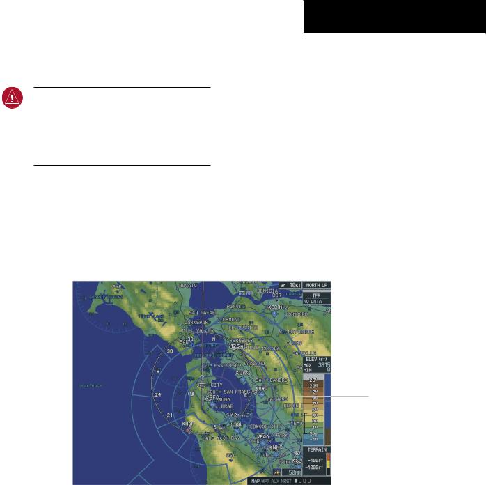
7.2 NAVIGATION MAP PAGE
WARNING:Use of the Navigation Map Page for pilotagenavigationisprohibited. TheNavigation Map is intended only to enhance situational awareness. Navigation is to be conducted using only current charts, data, and authorized navigation facilities.
The Navigation Map Page is the first page in the map page group and provides the pilot with the following GPS/Navigation display capability:
•Map display showing airports, navaids, airspaces, land data (highways, cities, lakes, rivers, borders, etc.) with names (labels)
MULTI FUNCTION DISPLAY
•Map pointer information (distance and bearing to pointer, location of pointer, name and other pertinent information)
•TIS Traffic Data
•Obstacle Data
•Map Zoom Range Legend
•Wind Direction and Speed
•Heading Indication
•Aircraft icon representing present position
•Icons for enabled map features
•Track Vector
•Topography Scale
•Fuel Range Ring
•Topography Data
•Terrain Proximity Data
•TAWS Data
Interstate |
|
|
|
|
|
|
|
|
|
|
|
Map Orientation |
|||||
|
|
|
|
|
|
|
|
|
|
|
|||||||
Highway |
|
|
|
|
|
|
|
|
|
|
|
Course Line |
|||||
|
|
|
|
|
|
|
|
|
|
|
|
|
|||||
|
|
|
|
|
|
|
|
|
|
|
|
|
|||||
|
|
|
|
|
|
|
|
|
|
|
|
|
|
Nav Range |
|||
Own Aircraft |
|
|
|
|
|
|
|
|
|
|
|
|
Ring |
||||
|
|
|
|
|
|
|
|
|
|
|
|
|
|
Airspace Boundries |
|||
|
|
|
|
|
|
|
|
|
|
|
|
|
|
||||
|
|
|
|
|
|
|
|
|
|
|
|
|
|
|
|
|
|
|
|
|
|
|
|
|
|
|
|
|
|
|
|
|
Topo Scale |
||
|
|
|
|
|
|
|
|
|
|
|
|
|
|
|
|||
|
|
|
|
|
|
|
|
|
|
|
|
|
|
|
|
|
Terrain Scale |
|
|
|
|
|
|
|
|
|
|
|
|
|
|
|
|
|
|
|
|
|
|
|
|
|
|
|
|
|
|
|
|
|
|
Map Scale |
|
Page Groups |
|
|
|
|
|
|
|
|
|
|
|
|
|
|
|
Legend |
|
|
Figure 7-8 Navigation Map Page |
||||||||||||||||
|
|
|
|||||||||||||||
|
|
|
(not all features shown) |
||||||||||||||
190-00498-00 Rev.A |
Garmin G1000 Pilot’s Guide for Cessna Nav III |
7-9 |

MULTI FUNCTION DISPLAY
To select the Navigation Map Page:
1.Turn the largeFMSknob to select the Map Page group.
2.Turn the small FMS knob to select the Navigation Map Page.The page group name and page title is displayed below the navigation status bar; MAP – NAVIGATION MAP. In addition to turning the large and small FMS knobs, the Navigation Map Page can be selected from any page by pressing and momentarily holding the CLR (DFLT MAP) key.
7-10 |
Garmin G1000 Pilot’s Guide for Cessna Nav III |
190-00498-00 Rev.A |

NAVIGATION MAP PAGE OPERATIONS
The following Navigation Map Page operations can be performed:
•Changing the Map Orientation
•Selecting a Map Range
•Using the Auto Zoom Feature
•Identifying Aviation Map Data
•Decluttering the Map
•Panning the Map
•Displaying Topographic Information on the Navigation Map Page
•Displaying Terrain Information on the Navigation Map Page
•Displaying Traffic on the Navigation Map Page
•MFD Navigation Status Window
•Navigation Map Page Options Menu
Changing the Map Orientation
See the map setup section of this MFD Pilot’s Guide for instructions on how to change the map orientation.
MULTI FUNCTION DISPLAY
Selecting a Map Range
The Navigation Map Page can be set to 23 different range settings from 500 feet to 2000 nautical miles. The current range is indicated in the lower right corner of the Navigation Map Page and represents the top-to-bottom distance covered by the map. To change the map range turn the joystick counter-clockwise to zoom in, turn it clockwise to zoom out.
Using the Auto Zoom Feature
The autozoom feature automatically adjusts the map from an enroute range of 2000 nm through each lower range, stopping at a range of 1.5 nm as the aircraft approaches the destination waypoint. See the Map Setup section in this MFD Pilot’s Guide for instructions on enabling/disabling the autozoom feature.
Map Range
Indicator
Figure 7-9 Map Range Indicator
190-00498-00 Rev.A |
Garmin G1000 Pilot’s Guide for Cessna Nav III |
7-11 |

MULTI FUNCTION DISPLAY
Identifying Aviation Map Data
The following aviation data is displayed on the
Navigation Map Page:
Airport Symbols:
•Non-towered airports (purple in color).
•Towered airports (blue in color).
•Non-serviced airports (displayed as solid circle icons). See Appendix F for symbology definitions.
•Serviced airports (displayed as circles with protruding tick marks pointing to the top, bottom, left, and right portions of the screen).
Classification:
•Unclassified airports (displayed with a question mark “?” character centered within the airport symbol).
•Restricted airports (displayed with the letter “R” centered within the airport symbol).
•Hard surface public airports (displayed with the airports longest runway oriented according to the direction in which it runs centered within the airport symbol).
•Heliports (displayed with the letter “H” centered within the heliport symbol).
•Soft surface public airports (displayed with a hollow circle in the center of the airport symbol).
Airspace:
The Navigation Map Page displays airspace as one of the following colors:
•Blue:
ICAO control area Class B, Alert area
Caution area, Danger area, Prohibited area Restricted area, Training area
Unknown area, Warning area Terminal Zone Airspace (ATZ), Class D
•Purple: Class C
ICAO terminal control area Terminal radar service area (TRSA) Mode C area
Military operations area (MOA) Mode C
Class A Class E
Line Style:
The Navigation Map Page displays airspace as one of the following line styles:
•Solid line: Class C
ICAO control area
ICAO terminal control area
Class B, Terminal radar service area Mode C, Class A
•Dashed line: Mode C tower area Class D, Class E
•Consecutive parallel lines forming a boundary defining the airspace: Military operations area (MOA) Warning area, Alert area, Caution area Danger area, Prohibited area Restricted area, Training area
Unknown area, Terminal Zone Airspace (ATZ)
NOTE: See Appendix F for a complete description of the aviation map symbology used on the Navigation Map Page.
7-12 |
Garmin G1000 Pilot’s Guide for Cessna Nav III |
190-00498-00 Rev.A |

Decluttering the Map
The Navigation Map Page can be quickly decluttered by repeatedly pressing the DCLTR softkey until the desired detail is displayed. The declutter level label is displayed above the DCLTR softkey. Note that during an instrument approach, automatic decluttering takes place. Table 7.2.1 lists the features that are turned off at each declutter level.
MULTI FUNCTION DISPLAY
NOTE: Some of the map features are automatically removed at certain zoom ranges due to the map setup configuration for each map item.
NOTE: “SUA” listed in the table below stands for Special Use Airspace. These are controlled airspaces, military zones, etc.
Map Features always |
No Declutter |
Declutter ( –1) |
Declutter (-2) |
Declutter (-3) |
displayed |
|
|
|
|
Flight plan route lines |
All Map features |
River/Lakes Names Only |
User waypoints |
Large Airports |
|
are visible |
|
|
|
Flight plan route waypoints |
|
Land/Country Text |
Latitude/Longitude Grid |
Medium Airports |
Rivers/Lakes |
|
Large City |
VORs |
Small Airports |
Topography data |
|
Medium City |
NDBs |
SUA Group 3 |
Terrain and Obstacles |
|
Small City |
Intersections |
SUA Group 4 |
Map Borders |
|
----------- |
SUA Group 0 |
Runway Labels |
Bearing Line |
|
Freeways |
SUA Group 1 |
|
Lightning Strike data (when |
|
National Highways |
SUA Group 2 |
|
Stormscope installed) |
|
|
|
|
Nexrad data |
|
Local Highways |
SUA Group 5 |
|
Traffic Symbols |
|
Local Roads |
SUA Group 6 |
|
Traffic Labels |
|
Local Road Labels |
SUA Group 7 |
|
|
|
Railroads |
Obstacles |
|
|
|
Major Political Boundaries |
|
|
|
Table 7-1 Map Declutter Levels |
|
|
|
190-00498-00 Rev.A |
Garmin G1000 Pilot’s Guide for Cessna Nav III |
7-13 |

MULTI FUNCTION DISPLAY
Map Panning
Map panning moves the map beyond its current limits without adjusting the map range. When the panning function is selected by pushing in the joystick, a panning arrow flashes on the map display. A window also appears at the top of the map display showing the latitude/longitude position of the pointer, the bearing and distance to the pointer from the aircraft’s present position, and the elevation of the land at the position of the pointer. When the panning arrow crosses an airspace boundary, the boundary is highlighted and airspace information is displayed at the top of the display. The information includes the name and class of airspace, the ceiling in feet expressed in Mean Seal Level (MSL), and the floor in feet MSL.
NOTE:The airspace boundary stays highlighted for approximately four seconds before returning to normal shading.
To pan the map:
1.Push in the joystick to display the panning arrow.
2.Move the joystick in the general direction of the desired destination to place the panning arrow at the destination location. When the panning arrow is placed on an object, the name of the object is highlighted (even if the name wasn’t originally displayed on the map). This feature applies to everything displayed on the map except route lines. When any map feature or object is selected on the map display, features or objects are displayed in the box located at the top of the display. From here, the pilot can designate the waypoint as the Direct-to destination. When the panning arrow crosses an airspace boundary, the boundary is highlighted and airspace information is displayed at the top of the display.
3.To remove the panning arrow and return to the present position, push in the joystick.
7-14 |
Garmin G1000 Pilot’s Guide for Cessna Nav III |
190-00498-00 Rev.A |
MULTI FUNCTION DISPLAY
Distance, |
|
Latitude and longitude |
||
bearing |
|
|
|
position of pointer |
|
|
|||
and elevation |
|
|
||
Panning
Arrow
Figure 7-10 Map Panning
190-00498-00 Rev.A |
Garmin G1000 Pilot’s Guide for Cessna Nav III |
7-15 |
MULTI FUNCTION DISPLAY
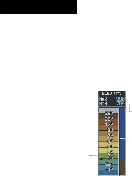
Displaying Topographic Data on the Navigation Map Page
The Navigation Map Page displays various shades of topography land colors representing the rise and fall of land elevation similar to aviation sectional charts. The Navigation Map Page can display a topographic scale representing various key points of terrain elevation colors with their associated elevation value labeled.
To display topographic data on the Navigation Map Page:
1.Press the MAP softkey.
2.Press the TOPO softkey. Topo data can also be displayed on the Navigation Map Page by using the‘On/Off’ topo data map setup feature. See the Navigation Map Page setup menu section.
On-screen map maximum elevation
On-screen map minimum elevation
Aircraft altitude
Maximum
Ground elevation
Minimum
Figure 7-11 Topography Range
7-16 |
Garmin G1000 Pilot’s Guide for Cessna Nav III |
190-00498-00 Rev.A |

NOTE: Press the TOPO softkey again to remove topo data from the Navigation Map Page. When topo data is removed from the page, the Jeppesen Nav data is presented on a black background.
Displaying Terrain and Obstacles on the Navigation Map Page
Terrain and Obstacles can be displayed on the Navigation Map Page by pressing the TERRAIN softkey. Terrain symbology (mountain icons) appear next to the map range in the bottom right corner of the page indicating the presence of terrain data on the map. See the Terrain Proximity Page section for a terrain color interpretation chart.
To display terrain and obstacle data on the Navigation Map Page:
1.Press the MAP softkey.
2.Press the TERRAIN softkey. Press the TERRAIN softkey again to remove terrain data from the Navigation Map Page.
MULTI FUNCTION DISPLAY
Displaying Traffic on the Navigation Map Page
Pressing the TRAFFIC softkey displays Traffic Information Service (TIS) traffic on the Navigation Map Page. TIS is a ground-based service providing relative location of all ATCRBS Mode-A and Mode-C transponder equipped aircraft within a specified service volume.
The TIS ground sensor uses real time track reports to generate traffic notification. Surveillance data includes all transponder-equipped aircraft within the coverage volume. The G1000 displays up to eight traffic targets within a 7.5 nautical mile radius, from 3,000 feet below to 3,500 feet above the requesting aircraft. See Appendix E for a full description of TIS. A traffic symbol appears next to the map range in the bottom right corner of the display indicating the presence of traffic data on the map.
To display traffic on the Navigation Map Page:
1.Press the MAP softkey.
2.Press the TRAFFIC softkey. Press the TRAFFICsoftkeyagaintoremovetrafficfromthe Navigation Map Page.
NOTE: Traffic and terrain data can also be displayed by using the ‘On/Off’ Navigation Map Page option. See the Navigation Map Page setup section for details.
190-00498-00 Rev.A |
Garmin G1000 Pilot’s Guide for Cessna Nav III |
7-17 |

MULTI FUNCTION DISPLAY
MFD Data Bar
The MFD Navigation Status Window displays four, user-configurable fields which can display the following data:
•Bearing to next waypoint (BRG)
•Distance to next waypoint (DIS)
•Desired track to next waypoint (DTK)
•En-route safe altitude (ESA)
•Estimated Time of Arrival (ETA)
•Estimated Time Enroute (ETE)
•Ground Speed (GS)
•Maximum Safe Altitude (MSA)
•Track angle error (TKE)
•Track angle (TRK)
•Vertical speed required (VSR)
•Cross track error (XTK)
•Currently selected MFD page title
Figure 7-12 MFD Data Bar (default)
NOTE: Instructions on changing a data field on the MFD Data Bar is given in the System Setup Section.
Navigation Map Page Options Menu
The Navigation Map Page can be customized using options listed in the Navigation Map Page menu. To display the menu, press the MENU key (with the Navigation Map Page displayed). Two options are available: Map Setup, and Measure Bearing/Distance.
Map Setup
The first option is ‘Map Setup’ which is used to configure the Navigation Map Page including map orientation, land data enable/disable, Jeppesen data enable/disable, automatic zoom, airspace boundaries, and text size.
Map Group Options
Figure 7-13 Map Group Setup Options
7-18 |
Garmin G1000 Pilot’s Guide for Cessna Nav III |
190-00498-00 Rev.A |

Orientation
There are four map orientation selections: North up, Track up, DTK up, and HDG up.
•North up fixes the top of the map to a north heading.
•Track up adjusts the top of the map display to the current ground track.
•Desired Track Up (DTK up) fixes the top of the map display to the desired course.
•Heading Up (HDG up) fixes the top of the map display to the current aircraft heading.
NOTE: The Navigation Map Page orientation default setting is ‘North Up’.
MULTI FUNCTION DISPLAY
To change the map orientation:
1.With the Navigation Map Page displayed,press the MENU key to display the Navigation Map Page Menu. The cursor flashes on the ‘Map Setup’ option.
2.Press the ENT key. The Map Setup Menu is displayed.
3.Turn the small FMS knob to select the ‘Map’ group and press the ENT key.
4.Turn the large FMS knob to highlight the ‘ORIENTATION’ field.
5.Turn the small FMS knob to select the desired orientation and press the ENT key.
6.Press the FMSknob to return to the Navigation Map Page.
190-00498-00 Rev.A |
Garmin G1000 Pilot’s Guide for Cessna Nav III |
7-19 |

MULTI FUNCTION DISPLAY
Auto Zoom
The automatic zoom feature automatically adjusts the map range from 2000 nm through each lower range, stopping at 1.5 nm as the aircraft approaches the destination waypoint.
To enable/disable automatic zoom:
1.With the Navigation Map Page displayed,press the MENU key to display the Navigation Map Page Menu. The cursor flashes on the ‘Map Setup’ option.
2.Press the ENT key. The Map Setup Menu is displayed.
3.Turn the small FMS knob to select the ‘Map’ group and press the ENT key.
4.Turn the largeFMS knob to highlight the‘AUTO ZOOM’ field.
5.Turn the small FMS knob to select ‘On’ or ‘Off’ and press the ENT key.
6.Press the FMSknob to return to the Navigation Map Page.
Land Data
TheNavigationMapPagecandisplaybackgroundland data (roads, lakes, borders, etc). The background land data can also be removed from the display (turned off).
To enable/disable land data:
1.With the Navigation Map Page displayed,press the MENU key to display the Navigation Map Page Menu. The cursor flashes on the ‘Map Setup’ option.
2.Press the ENT key. The Map Setup Menu is displayed.
3.Turn the small FMS knob to select the ‘Map’ group and press the ENT key.
4.Turn the largeFMS knob to highlight the‘LAND DATA’ field.
5.Turn the small FMS knob to select ‘On’ or ‘Off.’ and press the ENT key.
6.Press the FMSknob to return to the Navigation Map Page.
7-20 |
Garmin G1000 Pilot’s Guide for Cessna Nav III |
190-00498-00 Rev.A |

Track Vector
The Navigation Map Page can display a track vector as a dashed cyan line segment with an arrowhead attached to the end, extended to a predicted location in 60 seconds along the current aircraft track. The track vector is useful in minimizing track angle error.
To enable/disable the track vector:
1.With the Navigation Map Page displayed,press the MENU key to display the Navigation Map Page Menu. The cursor flashes on the ‘Map Setup’ option.
2.Press the ENT key. The Map Setup Menu is displayed.
3.Turn the small FMS knob to select the ‘Map’ group and press the ENT key.
4.Turn the large FMS knob to highlight the ‘TRACK VECTOR’ field.
5.Turn the small FMS knob to select ‘On’ or ‘Off’. Press the ENT key to accept the selected option.
6.Press the FMSknob to return to the Navigation Map Page.
MULTI FUNCTION DISPLAY
Wind Vector
The wind vector box is displayed in the upper right corner of the Navigation Map Page and displays wind direction and speed (in knots). Wind direction is indicated by a 360 degree pointing arrow.
To enable/disable the wind vector box:
1.With the Navigation Map Page displayed,press the MENU key to display the Navigation Map Page Menu. The cursor flashes on the ‘Map Setup’ option.
2.Press the ENT key. The Map Setup Menu is displayed.
3.Turn the small FMS knob to select the ‘Map’ group and press the ENT key.
4.Turn the largeFMS knob to highlight the‘WIND VECTOR’ field.
5.Turn the small FMS knob to select ‘On’ or ‘Off’. Press the ENT key to accept the selected option.
6.Press the FMSknob to return to the Navigation Map Page.
190-00498-00 Rev.A |
Garmin G1000 Pilot’s Guide for Cessna Nav III |
7-21 |

MULTI FUNCTION DISPLAY
Nav Range Ring
The Nav range ring shows the direction of travel (ground track) on a rotating compass card. The range of theNavcompassisdeterminedbythemaprange,125feet (500 feet map range) to 500 nm (2000 nm map range).
To enable/disable the Nav range ring:
1.With the Navigation Map Page displayed,press the MENU key to display the Navigation Map Page Menu. The cursor flashes on the ‘Map Setup’ option.
2.Press the ENT key. The Map Setup Menu is displayed.
3.Turn the small FMS knob to select the ‘Map’ group and press the ENT key.
4.Turn the large FMS knob to highlight the ‘NAV RANGE RING’ field.
5.Turn the small FMS knob to select ‘On’ or ‘Off’. Press the ENT key to accept the selected option.
6.Press the FMSknob to return to the Navigation Map Page.
Topo Data
Topographic data can be enabled or disabled on the Navigation Map Page using the ‘TOPO DATA’ setting. The topo data range is the maximum map range that topo data is displayed.
To enable/disable topo data and to select a topo data range:
1.With the Navigation Map Page displayed,press the MENU key to display the Navigation Map Page Menu. The cursor flashes on the ‘Map Setup’ option.
2.Press the ENT key. The Map Setup Menu is displayed.
3.Turn the small FMS knob to select the ‘Map’ group and press the ENT key.
4.Turn the largeFMS knob to highlight the‘TOPO DATA’ field.
5.Turn the small FMS knob to select ‘On’ or ‘Off’.
6.Press the ENTkey to accept the selected option. The flashing cursor highlights the range field. TOPO ranges are from Off to 2000 nm.
7.To change the TOPO range setting, turn the small FMS knob to display the range list.
8.Turn the small FMS knob to select the desired range and press the ENT key.
9.Press the FMSknob to return to the Navigation Map Page.
NOTE:When topographic data is removed from the Navigation Map Page, all cartographic data is automatically removed and the Jeppesen Nav data is presented on a black background.
7-22 |
Garmin G1000 Pilot’s Guide for Cessna Nav III |
190-00498-00 Rev.A |

Topo Range
The topo range setting enables or disables the topography range box located in the lower right corner of the Navigation Map Page.
To enable/disable the topo range box:
1.With the Navigation Map Page displayed,press the MENU key to display the Navigation Map Page Menu. The cursor flashes on the ‘Map Setup’ option.
2.Press the ENT key. The Map Setup Menu is displayed.
3.Turn the small FMS knob to select the ‘Map’ group and press the ENT key.
4.Turn the largeFMS knob to highlight the‘TOPO Range’ field.
5.Turn the small FMS knob to select ‘On’ or ‘Off’.
6.Press the ENT key to accept the selected option.
7.Press the FMSknob to return to the Navigation Map Page.
MULTI FUNCTION DISPLAY
Terrain Data
Terrain data can be enabled or disabled on the Navigation Map Page using the ‘TERRAIN DATA’ setting. A data range can also be selected. The data range is the maximum map range that terrain data is displayed.
To enable/disable terrain data and to select a terrain data range:
1.With the Navigation Map Page displayed,press the MENU key to display the Navigation Map Page Menu. The cursor flashes on the ‘Map Setup’ option.
2.Press the ENT key. The Map Setup Menu is displayed.
3.Turn the small FMS knob to select the ‘Map’ group and press the ENT key.
4.Turn the large FMS knob to highlight the ‘TERRAIN DATA’ field.
5.Turn the small FMS knob to select ‘On’ or ‘Off’.
6.Press the ENTkey to accept the selected option. The flashing cursor highlights the range field. TERRAIN ranges are from Off to 2000 nm.
7.To change theTERRAIN range setting,turn the small FMS knob to display the range list.
8.Turn the small FMS knob to select the desired range and press the ENT key.
9.Press the FMSknob to return to the Navigation Map Page.
190-00498-00 Rev.A |
Garmin G1000 Pilot’s Guide for Cessna Nav III |
7-23 |

MULTI FUNCTION DISPLAY
Obstacle Data
Obstacle data can be enabled or disabled on the Navigation Map Page using the ‘OBSTACLE DATA’ setting. A data range can also be selected. The data range is the maximum map range that terrain data is displayed.
To enable/disable obstacle data and to select a terrain data range:
1.With the Navigation Map Page displayed,press the MENU key to display the Navigation Map Page Menu. The cursor flashes on the ‘Map Setup’ option.
2.Press the ENT key. The Map Setup Menu is displayed.
3.Turn the small FMS knob to select the ‘Map’ group and press the ENT key.
4.Turn the large FMS knob to highlight the ‘OBSTACLE DATA’ field.
5.Turn the small FMS knob to select ‘On’ or ‘Off’.
6.Press the ENTkey to accept the selected option. The flashing cursor highlights the range field. OBSTACLE ranges are from Off to 50 nm.
7.To change the OBSTACLE range setting, turn the small FMS knob to display the range list.
8.Turn the small FMS knob to select the desired range and press the ENT key.
9.Press the FMSknob to return to the Navigation Map Page
Fuel Range Ring (Fuel RNG) (RSV)
The Navigation Map Page can display a fuel range ring which shows the flight distance that the aircraft has remaining. A dashed green circle indicates the transition range to reserve fuel. A solid green circle indicates the range of all fuel, including the reserve fuel. If only reserve fuel remains, the range is indicated by a solid yellow circle.
To enable/disable the fuel range ring and to select a fuel range time:
1.With the Navigation Map Page displayed,press the MENU key to display the Navigation Map Page Menu. The cursor flashes on the ‘Map Setup’ option.
2.Press the ENT key. The Map Setup Menu is displayed.
3.Turn the small FMS knob to select the ‘Map’ group and press the ENT key.
4.Turn the largeFMS knob to highlight the‘FUEL RNG (RSV)’ field.
5.Turn the small FMS knob to select ‘On’ or ‘Off’.
6.Press the ENTkey to accept the selected option. The flashing cursor highlights the fuel reserve time field. The time indicated is the time the aircraft can fly with remaining fuel on board.
7.To change the reserve fuel time,turn either the FMS knob to enter a time (00:00 to 23:59; hours:minutes). The default setting is 00:45 minutes. Press the ENT key.
8.Press the FMSknob to return to the Navigation Map Page.
7-24 |
Garmin G1000 Pilot’s Guide for Cessna Nav III |
190-00498-00 Rev.A |
Traffic Group
The display of traffic information on the Navigation Map Page closely resembles TCAS display symbology. Traffic is only displayed on the Navigation Map Page if aircraft heading data is available. If heading is not available, traffic advisories are displayed as non-bearing banners on the Navigation Map Page.
Figure 7-14 Traffic Group Options
MULTI FUNCTION DISPLAY
To enable/disable traffic data on the Navigation Map Page:
1.With the Navigation Map Page displayed,press the MENU key to display the Navigation Map Page Menu. The cursor flashes on the ‘Map Setup’ option.
2.Press the ENT key. The Map Setup Menu is displayed
3.Turn the small FMS knob to select the ‘Traffic’ group. Press the ENT key. The cursor flashes on the ‘TRAFFIC’ field.
4.Turn the small FMS knob to select ‘On’ or ‘Off’.
5.Press the ENT key to accept the selected option.
6.Press the FMSknob to return to the Navigation Map Page.
The ‘Traffic’ mode selects which traffic is displayed (all traffic,trafficandproximityadvisories,ortrafficadvisories only). The traffic symbol is the symbol used to depict the type of traffic:
•Traffic Advisories (TA) – Yellow
•Proximity Advisories (PA) – White
•Other – White
Proximity Advisories (PAs) are displayed as solid white Cessnas. PAs are defined as traffic within the 4.0 nm range, within ± 1200 ft. of altitude separation, and are not traffic advisories (TAs).
190-00498-00 Rev.A |
Garmin G1000 Pilot’s Guide for Cessna Nav III |
7-25 |

MULTI FUNCTION DISPLAY
To select a traffic mode:
1.With the Navigation Map Page displayed,press the MENU key to display the Navigation Map Page Menu. The cursor flashes on the ‘Map Setup’ option.
2.Press the ENT key. The Map Setup Menu is displayed.
3.Turn the small FMS knob to select the ‘Traffic’ group Press the ENT key. The cursor flashes on the ‘TRAFFIC’ field.
4.Turn the largeFMSknob to highlight the‘TRAFFIC MODE’ field.
5.Turn the small FMS knob to select the desired option.
6.Press the ENT key to accept the selected option.
7.Press the FMSknob to return to the Navigation Map Page.
To select a traffic symbol zoom range:
1.With the Navigation Map Page displayed,press the MENU key to display the Navigation Map Page Menu. The cursor flashes on the ‘Map Setup’ option.
2.Press the ENT key. The Map Setup Menu is displayed
3.Turn the small FMS knob to select the ‘Traffic’ group. Press the ENT key. The cursor flashes on the ‘TRAFFIC’ field.
4.Turn the large FMS knob to highlight the ‘TRAFFIC SMBL’ field. Traffic symbol zoom ranges are from Off to 300 nm.
5.Turn the small FMS knob to select the desired option.
6.Press the ENT key to accept the selected option.
7.Press the FMS knob to return to the Navigation Map Page.
7-26 |
Garmin G1000 Pilot’s Guide for Cessna Nav III |
190-00498-00 Rev.A |

The traffic label displays the altitude separation above or below the symbol and the vertical speed sense arrow to the right of the symbol.
To select a traffic label zoom range:
1.With the Navigation Map Page displayed,press the MENU key to display the Navigation Map Page Menu. The cursor flashes on the ‘Map Setup’ option.
2.Press the ENT key. The Map Setup Menu is displayed
3.Turn the small FMS knob to select the ‘Traffic’ group. Press the ENT key. The cursor flashes on the ‘TRAFFIC’ field.
4.Turn the large FMS knob to highlight the ‘TRAFFIC LBL’ field. Traffic label zoom ranges are from Off to 300 nm.
5.Turn the small FMS knob to select the desired option.
6.Press the ENT key to accept the selected option.
7.Press the FMSknob to return to the Navigation Map Page.
Aviation Group Options
•Active Flight Plan (ACTIVE FPL)- the active flight plan zoom range sets the maximum range at which the active flight plan magenta line is displayed on the display (off - 2000 nm).
•Active Flight Plan Waypoint (ACTIVE FPL WPT)- the active flight plan waypoint label size sets the size at which the active flight plan names appear on the display (none, small, medium, and large). The zoom range sets the maximum range at which active flight plan waypoints appear on the display (off - 2000 nm).
MULTI FUNCTION DISPLAY
•Large, Medium, and Small Airports (LARGE APT, MEDIUM APT, SMALL APT) - The airport label size sets the size at which the large, medium, or small airport names size appear on the display. The zoom range sets the maximum range at which the airports appear on the display:
•Large: off - 500 nm
•Medium: off - 300 nm
•Small: off - 100 nm
•Intersection, Non-Directional Beacon, and VOR Waypoints (INT WAYPOINT, NDB WAYPOINT, VOR WAYPOINT) - The INT, NDB, and VOR label size sets the maximum range at which the navaids names appear on the display. The zoom range sets the maximum range at which the navaids appear on the display:
•INT: off - 30 nm
•NDB: off - 30 nm
•VOR: off - 300 nm
190-00498-00 Rev.A |
Garmin G1000 Pilot’s Guide for Cessna Nav III |
7-27 |

MULTI FUNCTION DISPLAY
•Airspace Boundaries (CLASS B/TMA, CLASS C/TCA, andCLASSD)-Theairspacezoomrangesetsthemaximum range at which the three classes of airspace appear on the display. The zoom range sets the maximum range at which the airspace boundaries appear on the display:
•CLASS B: off - 500 nm
•CLASS C: off - 500 nm
•CLASS D: off - 300 nm
•“Other” Airspace Boundaries (RESTRICTED, MOA (Military), OTHER AIRSPACE, nad TFR (temporary flight restrictions)- the other airspace boundary zoom range sets the maximum range at which restricted, MOA, and other (training, caution, danger, warning and alert areas) airspace boundaries are displayed
•RESTRICTED: off - 500 nm
•MOA (MILITARY): off - 500 nm
•OTHER AIRSPACE: off - 500 nm
•TFR; (only present when GDL 69 is installed): off - 2000 nm
To select an aviation group item range:
1.With the Navigation Map Page displayed,press the MENU key to display the Navigation Map Page Menu. The cursor flashes on the ‘Map Setup’ option.
2.Press the ENT key. The Map Setup Menu is displayed.
3.Turn the smallFMS knob to select the‘Aviation’ group. Press the ENT key. The cursor flashes on the ‘ACTIVE FPL’ field.
4.Turn the large FMS knob to select the desired option.
5.Turn the small FMS knob to select the desired range.
6.Press the ENT key to accept the selected option.
7.Press the FMSknob to return to the Navigation Map Page.
Figure 7-15 Aviation Group Options
7-28 |
Garmin G1000 Pilot’s Guide for Cessna Nav III |
190-00498-00 Rev.A |

To select an aviation group item text size:
1.With the Navigation Map Page displayed,press the MENU key to display the Navigation Map Page Menu. The cursor flashes on the ‘Map Setup’ option.
2.Press the ENT key. The Map Setup Menu is displayed.
3.Turn the smallFMS knob to select the‘Aviation’ group. Press the ENT key. The cursor flashes on the ‘ACTIVE FPL’ field.
4.Turn the large FMS knob to select the desired option.
5.Turn the small FMS knob to select the desired text size.
6.Press the ENT key to accept the selected text size.
7.Press the FMSknob to return to the Navigation Map Page.
Land Group Options
•Latitude/Longitude (LAT/LON) - the LAT/LON label size sets the size at which latitude/longitude labels appear on the display (none, small, medium, and large). The zoom range sets the maximum range at which LAT/LON waypoints appear on the display (off - 2000 nm).
•Highways, Roads, and Railroads (FREEWAY, LOCAL HWY, LOCAL ROAD, RAILROAD) - The highway and road zoom range sets the maximum range at which highways, roads, and railroads appear on the display:
•FREEWAY: off - 800 nm
•NATIONAL HWY: off - 80 nm
•LOCAL HWY: off - 30 nm
•LOCAL ROAD: off - 15 nm
•RAILROAD: off - 30 nm
MULTI FUNCTION DISPLAY
• Cities and Towns (LARGE CITY, MEDIUM CITY, SMALL CITY) - The cities and town label size sets the maximum range at which city and town names appear on the display. The zoom range sets the maximum range at which cities and towns appear on the display:
•LARGE CITY (approximate populations greater than 200,000): off - 1500 nm
•MEDIUM CITY (approximate populations greater than 50,000): off - 200 nm
•SMALL CITY (approximate populations greater than 5,000): off - 50 nm
190-00498-00 Rev.A |
Garmin G1000 Pilot’s Guide for Cessna Nav III |
7-29 |

MULTI FUNCTION DISPLAY
• States and Provinces, Rivers and Lakes, and User Waypoints (STATE/PROV, RIVER/LAKE, USER WAYPOINT) - the label range sets the maximum range at which the three categories appear on the display. The zoom range sets the maximum range at which the three categories appear on the display:
•STATE/PROV: off - 1500 nm
•RIVER/LAKE off - 500 nm
•USER WAYPOINT: off - 300 nm
Figure 7-16 Land Group Options
To select a land group item range:
1.With the Navigation Map Page displayed,press the MENU key to display the Navigation Map Page Menu. The cursor flashes on the ‘Map Setup’ option.
2.Press the ENT key. The Map Setup Menu is displayed.
3.Turn the small FMS knob to select the ‘Land’ group. Press the ENT key. The cursor flashes on the ‘LAT/LON’ field.
4.Turn the large FMS knob to select the desired option.
5.Turn the small FMS knob to select the desired range. Press the ENT key to accept the selected option.
6.Press the FMSknob to return to the Navigation Map Page.
To select a land group item text size:
1.With the Navigation Map Page displayed,press the MENU key to display the Navigation Map Page Menu. The cursor flashes on the ‘Map Setup’ option.
2.Press the ENT key. The Map Setup Menu is displayed.
3.Turn the small FMS knob to select the ‘Land’ group. Press the ENT key. The cursor flashes on the ‘LAT/LON’ field.
4.Turn the large FMS knob to select the desired option.
5.Turn the small FMS knob to select the desired text size. Press the ENT key to accept the selected option
6.Press the FMSknob to return to the Navigation Map Page.
7-30 |
Garmin G1000 Pilot’s Guide for Cessna Nav III |
190-00498-00 Rev.A |

MULTI FUNCTION DISPLAY
Measure Bearing/Distance
The second map setup option is ‘Measure Bearing/ Distance’ which provides a quick and easy method for determining the bearing and distance between any two points on the Navigation Map Page.
NOTE:Pressing the ENT key at any location with the‘Measure’ option enabled allows bearing and distance from the newly selected position to be acquired.
To measure bearing and distance between two points:
1.Press the MENU key (with the Navigation Map Page displayed).
2.Turn the small FMS knob to highlight the ‘Measure Bearing/Distance’ field and press the ENT key. An on-screen reference pointer is displayed on the map display at the aircraft’s present position.
3.Move the joystick to place the reference pointer at the desired location. The bearing and distance is displayed at the top of the map display. Elevation at the current position is also displayed.
4.To exit the Measure Bearing/Distance option, push in the joystickor select‘Stop Measuring’ from the page menu options.
190-00498-00 Rev.A |
Garmin G1000 Pilot’s Guide for Cessna Nav III |
7-31 |

MULTI FUNCTION DISPLAY
Bearing,
Distance, and
Elevation
Information
Reference
Pointer
Figure 7-17 Measuring Bearing and Distance
Pointer
Latitude and
Longitude
7-32 |
Garmin G1000 Pilot’s Guide for Cessna Nav III |
190-00498-00 Rev.A |