

Biomedical EPR Part-B Methodology Instrumentation and Dynamics - Sandra R. Eaton
.pdfLOOP-GAP RESONATORS |
29 |
It is often desirable to have the LGR designed for a standard 4 mm sample tube. However, when there is unlimited sample better S/N can be obtained, particularly for lossless samples, by using a larger LGR at low frequencies (Froncisz et al., 1989; Halpern et al., 1989; Rinard et al., 2002a). A 4 mm loop is somewhat large for X-band, and the capacitance gap becomes narrow and the gap large. To alleviate this, multiple gaps and reentrant loops can be used as shown in Figure 3 (Wood et al., 1984; Rinard et al., 1994). Since the gaps are effectively in series, each can be reduced in size nearly proportional to the number of gaps used. The thin-film LGRs can also be made with multiple gaps (Ghim et al., 1996).
The standard  rectangular cavity has many properties favorable as a “multipurpose” resonator, and Hyde et al. (1989) created a 3-loop-2-gap LGR having a form factor similar to the multipurpose cavity, so that it could use the accessories designed for the Varian E-231 cavity. For example, the central loop is the same diameter (11 mm) as the sample access stack of the E231 cavity resonator so standard EPR Dewars and flat cells fit it, and the coupling to the waveguide is similar to the Varian coupler.
It is also possible to place a loop-gap-type resonator inside a standard cavity resonator to increase the  at the sample relative to that in the cavity without the LGR inserted (Anderson et al., 1985; Britt and Klein, 1987).
6.COUPLING TO RESONATORS
The LGR can be designed as a series L–C circuit. The inductor, L, will have a series resistance on the order of milliohms, which will be the impedance of the circuit at resonance. The LGR can also be designed as a parallel L–C circuit, and at resonance, the low resistance in series with the inductor is transformed into a high resistance on the order of kiloohms or greater. For the most efficient coupling of power, and to prevent power reflection, the impedance of the resonator circuit must be equal to the characteristic impedance of the line (typically 50 ohms). Therefore, a coupling circuit is required between the resonator and the line to transform the very low or very high resistance into 50 ohms (Figure 4). Coupling (matching) a resonator to the microwave/RF transmission line is an important design and construction feature. Various types of transformers and electric probes have been used. The most common features have been moveable inductive loops or adjustable capacitors at the end of a semi-rigid coaxial cable, but Gordon couplers have also been used (Britt and Klein, 1987; Ichikawa et al., 1989; Oles et al., 1989).

30 |
GEORGE A. RINARD AND GARETH R. EATON |
Figure 4. A resonator (R, L, C) is coupled to a microwave source via a matching network, where is the spin system voltage and
  is the magnetic resonance signal voltage sensed at the detector side of the impedance matching network.
The coupling circuit should be as lossless as possible, and therefore is usually composed of low loss inductors and/or capacitors, which must be non-magnetic if they are close to the resonator. A thorough review of the various coupling techniques, complete with design equations is given in (Rinard et al., 1993). Inductive coupling was also analysed in the context of NMR coils used for imaging and spectroscopy (Froncisz et al. 1986). The most common coupling methods are series capacitive, and mutual inductive.
Imperfect electrical contact, mechanical instabilities, and/or backlash in the adjustable element can be the cause of noise or irreproducibility in the EPR spectra. Experience in many labs (unpublished) has been that wear of the adjustable elements limits the useful life of some resonators.
In series capacitive coupling, a series capacitor couples the parallel resonant L-C circuit to the transmission line. The frequency is adjusted until the L-C circuit is almost resonant but still inductive. The reactance of the series capacitor cancels this inductive component and the circuit is purely resistive. By adjusting the frequency and the size of the coupling capacitor, the value of the resultant resistive component can be varied over a wide range. Critical coupling is obtained when this resistive component is equal in value to the characteristic impedance of the line.
Mutual inductive coupling is obtained by means of a small loop on the end of the transmission line coupled to the inductance (loop) of the series L- C circuit. In this case, the coupling loop couples with the inductance of the resonator in a way to transform the very low resistance of the resonator loop into a resistance on the order of that of the characteristic impedance of the transmission line. When the impedances are equal, the resonator is critically coupled and the power reflected from the resonator/coupling circuit is a minimum (Poole, 1967, p.38; Rinard et al., 1993).
When series capacitance coupling is used, the resonant frequency of the coupled LGR system will be slightly lower than the resonant frequency of

LOOP-GAP RESONATORS |
31 |
the isolated LGR. With mutual inductive coupling the resultant resonant frequency will be slightly higher than that of the LGR itself. In either case the frequency will be closer to the LGR resonant frequency the higher the Q of the circuit, and the frequency difference will become larger if the resonator is overcoupled to reduce its Q for pulse application. This shift in frequency is of little consequence as far as the operation of the resonator is concerned, and for high Q resonators may be less than that caused by the sample.
Other types of coupling are possible, but in general they use the same types of reactive impedance transformations. The type of coupling used may depend more on the physical geometry of the LGR than electrical considerations. However, the LGR in general is a balanced structure and the coupling method should be balanced, particularly if there are significant openings in the shield. The common coaxial transmission line is not balanced. With insufficient shielding, RF currents can exit the LGR shield and flow on the outside of the coaxial line causing, at the least, hand waving effects. A balun (Balanis, 1982) is a device for converting from a balanced to an unbalanced configuration. Mutual inductive coupling is like a two winding transformer and acts somewhat like a balun, and may be preferable in some cases to capacitive coupling, but it is not perfectly balanced and for critical applications a balun may still be desirable.
7.DESIGN EQUATIONS
Design equations for LGRs and coupling are presented in (Froncisz and Hyde, 1982; Mehdizadeh et al., 1983; Wood et al., 1984; Froncisz et al., 1986; Rinard et al., 1993, 1994, 1999). Some of the more important equations are given below.
The LGR parameters are as follows: r = inside radius of loop, z = length of loop and gap, (distances are in meters)  = conductivity of loop, w = width of gap, n = number of gaps,
  is the permittivity of free space,
  (dimensionless) is the dielectric constant in the gap, and t = thickness of gaps.
  For mutual coupling,
  and
and 
are the self and mutual inductance of the coupling loop,  is the capacitance for series capacitance coupling, and
  is the characteristic impedance of the transmission line.
32 |
GEORGE A. RINARD AND GARETH R. EATON |
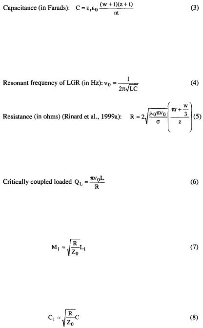
This formula is derived from the definition that the capacitance of a pair of parallel plates, each of area A and distance d apart is  where
where
the linear dimensions of the plate are increased by the plate spacing to account for electric field fringing.
Eq. (5) is the a.c. resistance due to skin effect. Eq. (5) is a modification of Rinard et al., 1999a, Eq. (29), as described in Rinard et al., 1999c, Eq. (17), to account for the linear distribution of the current in the gap.
Froncisz and Hyde (1982) provide equations for resonator frequency and for  from Hardy and Whitehead (1981) that accounts for the effects of the shield by including the dimensions of the resonator and shield.
Critical coupling mutual inductance (Rinard et al., 1993):
Where  is the mutual inductance between the input loop and the resonator loop, and
  is the inductance of the input loop.
Critical coupling series capacitance (Rinard et al., 1993):
LOOP-GAP RESONATORS |
33 |
Where  is the capacitance between the input line and the parallel loop and gap.
As a practical matter, characterization of a resonator in the laboratory will exploit the easiest measurements and use these to calculate other parameters of interest. One would measure the resonant frequency,  and Q, either in a spectrometer or with a network analyzer on a test bench. In the spectrometer, Q could be estimated by measuring the half-power bandwidth (Dalal et al., 1981) or the ring down time constant following a pulse. Of the calculations above, that of C is probably the most accurate, since the as-built dimensions will be known better than will the actual surface resistance after machining. However, the calculation of L would be the most accurate if the gap is very small or difficult to determine. Using the measured resonant frequency and the calculated C (or L), L (or C) can be determined from Eq.
(4). The calculated inductance (capacitance), together with the measured Q and  can be used to calculate the resistance R. The resistance will be of the order of a few hundredths of an ohm for typical small LGRs. Examples are given in Rinard et al., 1993, 1994 and 1999b.
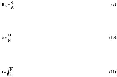
Once one has calculated the resistance, R, and the inductance, L, then it is possible to estimate the  per square root watt dissipated in the resonator. From first principles, (Rinard et al., 1999a)
 is the total magnetic flux in the loop of area A
  and
and  is the linearly polarized (total) component of magnetic field.
From the definition of inductance for a coil with N turns,
where I is the current in the walls of the resonator that generate the magnetic flux, and N is the number of turns.
Often, as in a simple one-loop LGR, N = 1. The current I is given by
Combining these formulae,

34 |
GEORGE A. RINARD AND GARETH R. EATON |
Because it is derived from power, this  is the RMS value. For EPR, we are interested in the magnitude (amplitude) of the circularly polarized (rotating) component of the magnetic field,
  The ratio of magnitude to
RMS is |
and the magnitude of the rotating component is |
that of the |
total field. |
Therefore, |
|
which now is in terms of parameters either measured or reliably estimated. The best experimental estimate of  is by pulsed methods. The power at which a maximum FID or echo is observed is approximately that corresponding to the
  for a
for a  pulse, if the pulse repetition time is long relative to
  A more precise measurement of the
  for a
for a  pulse is the null of the “T echo” in a three-pulse echo sequence,
 (echo) (Perman et al., 1989). If
  is smaller than T, the T echo is the
  echo of the 4 generated by this sequence (this is one of the echoes Mims
called “unwanted”).
where  is the pulse turning angle and
  is the length of the pulse. The magnetogyric ratio,
  for the electron is
The use of these equations is illustrated by calculations using parameters for a typical resonator. Consider a single-turn S-band LGR made of copper with: loop radius 2.03 mm, length 10.16 mm, gap width 3.05 mm and gap thickness 0.18 mm. The parameters calculated from Eqs. (2), (3), and (4) are
L = 1.34 nH, C = 1.66 pF, |
The measured Q was 590. |
Calculating R from Eq. (6) gives |
From Eq. (12b), |
LOOP-GAP RESONATORS |
35 |
8.MAGNETIC FIELD MODULATION
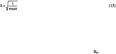
For most CW EPR measurements, it is important to modulate the magnetic field and use phase-sensitive detection (Poole, 1967) at the modulation frequency. In order to get the modulation field to the sample, either the metal of the shield and resonator has to be thin relative to the penetration (skin depth) at the modulation frequency (see Poole, 1967, pages 73-76), or there have to be breaks in the conductor. For example, thinly plated ceramic resonators can be used with magnetic field modulation, but resonators made of solid metal have to be either small in one dimension, as is the Bruker split-ring resonator, or have slots cut in them to allow modulation field penetration, as in several of the resonators described in our papers. The depth of penetration for electromagnetic energy is represented by the skin depth (Poole 1967, pp. 73-75)
In general, the resonator should be several skin depths thick at its resonant frequency in order to have a high Q and a fraction of a skin depth thick at the field modulation frequency for good modulation field penetration. For the resonator whose dimensions are given above, the metallic layer of the resonator should be on the order of 0.01 mm thick for a field modulation of up to ca. 100 KHz.
The purpose of field modulation is to encode the EPR signal with a
reasonably high frequency modulation of the magnetic field, |
and reduce |
the effect of low frequency noise (Anderson, 1960; Poole, |
1967). If the |
penetration of the resonator is low, eddy currents may be induced into the resonator structure that can interact with the static field and produce extraneous signals at the same frequency as the encoded EPR signal. Therefore, the penetration of the resonator to field modulation should be as good as possible while still maintaining a high Q. Resonators made of plated quartz or plated Macor ceramic usually have very little attenuation of the modulation field, but resonators made of solid metal with a few slots cut through the metal usually significantly attenuate the modulation field. We have found attenuations of ca. 30 to 40% in several resonators made of slotted solid metal.
A 300 MHz LGR with multilayer construction has been shown to yield greater modulation field penetration than a bridged loop-gap resonator, by suppression of eddy currents, while having similar Q values (Sato et al., 1999).

36 |
GEORGE A. RINARD AND GARETH R. EATON |
One might find mechanical resonances excited by the magnetic field modulation at particular modulation frequencies, which would then have to be avoided in operation. The eddy-current-induced noise depends on the amplitude of the magnetic field modulation, and may be the major contributor to noise in the EPR spectrum at high modulation amplitudes. Even with broad CW EPR spectra, the modulation-induced noise may be large enough that modulation larger than a few G might not be practical.
9.LGR FOR TIME DOMAIN EPR
Most of the parameters for a good CW LGR also apply for pulse applications. A critically coupled LGR is used for saturation recovery (SR), but it is necessary to be able to overcouple the resonator to low Q for FID and ESE measurements. Magnetic field modulation is not required for pulse applications. For CW, the EPR signal is in a very narrow band and centered about the spectrometry frequency. The spectrum is generated by sweeping the field at a frequency that is orders of magnitude lower than the RF frequency. In CW spectroscopy, noise is reduced by narrow band, low frequency filtering. In time domain EPR, the entire spectrum is recorded in a very short time, so the detector bandwidth has to be much larger that for CW EPR. The consequence of the large detector bandwidth needed for pulse EPR is that to obtain good S/N it is necessary to co-add many measurements of the response of the spin system.
The frequency excitation bandwidth of a pulse is also an important experimental parameter, affecting the selection of resonator Q. Mims (1965a,b) established a criterion for choice of Q in a pulse experiment by pointing out that for any shaped pulse, the Q must be equal to or less than that required to match the half power bandwidth of the resonator to the half power bandwidth of the pulse.
Other authors have expressed somewhat similar ideas in terms of other criteria, such as the width of the EPR signal excited. See, for example, Hornak and Freed (1986), Bowman (1990), Saalmuetter et al. (1995), and the discussion in Eaton and Eaton (2002). Since the focus here is on the resonator, the Mims criterion will be used in this Chapter.
The bandwidth of the resonator and spectrometer must be high enough (i.e., the Q low enough) to pass all of the frequency components of the pulse

LOOP-GAP RESONATORS |
37 |
and EPR spectrum. The loaded Q of the resonator can be expressed in terms of its bandwidth as,
Where  power resonator bandwidth. Therefore, large bandwidth requires a low
  The resonator will ring (exponentially damped oscillation at its resonance frequency) after the end of an RF pulse. The time constant of the power ring down is,
(when measuring signal voltage, the time constant will be twice this value) and there will be a dead time of as many as ca. 20 time constants, depending on signal strength, before the pulse power has decreased to the level that the much weaker EPR signal can be recorded. Although some researchers have constructed lossy resonators to obtain low  at critical coupling, the most efficient way to reduce the Q is by over coupling the resonator (Rinard et al., 1994). There is a complicated tradeoff between dead time (longer, the higher the Q) and EPR signal (higher, the higher the Q). The highest Q meeting the Mims criterion and consistent with experimental relaxation times will give the strongest EPR signal. If the experimental goal can accept a finite dead time, then the best EPR signal occurs with a Q that is larger than the minimum achievable by overcoupling. However, the experimental goal might be to observe a rapidly-decaying signal, or to observe echo envelope modulation, which require the minimum feasible dead time. These are experimental tradeoffs that will have to be optimized by each researcher. However, the Mims criterion yields a low enough Q to be a good starting point for such optimization.
For both pulse and CW applications an important parameter is resonator efficiency, defined by Eq. (19) as (Hyde and Froncisz, 1989),
where P is the power into the resonator, and  is the magnitude of the circularly polarized component of the microwave magnetic field.
Note that if the resonator is overcoupled, some power is reflected (see Rinard et al., 1994, and the worked example below), and the reflected power must be subtracted from the incident power to obtain the value of P used in Eq. (19). An important spectrometer system design criterion is the pulse
38 |
GEORGE A. RINARD AND GARETH R. EATON |
power required to generate the desired  in the resonator. From basic considerations it can be shown (Rinard et al., 1999a) that for a given frequency and resonator conductivity,
and that
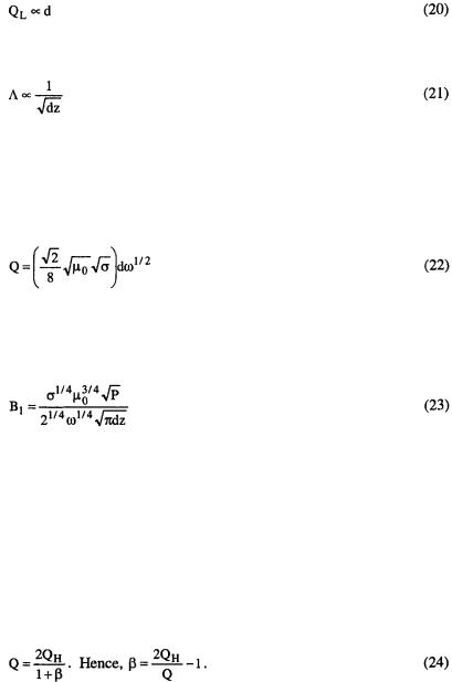
More extensive discussions of the scaling of  power required, etc., on the size and frequency of a resonator are in (Eaton et al., 1998; Rinard et al., 1999a, 1999b, 1999c). For convenience, we cite here useful equations from our prior papers, with notation specific to loop-gap-resonators (LGR), for Q and
where d is the diameter of the LGR,  is the permeability in a vacuum,
  is the conductivity of the surface of the resonator and
  is the EPR frequency.
where z is the length of the LGR.
If the resonator is overcoupled, then some of the power incident on the resonator is reflected from the resonator (Rinard et al., 1994). The following equations relate the reflected power, via the coupling coefficient,  to the resonator Q, which is often the most convenient measure of the degree of overcoupling, and thence to the power that gets to the sample in the resonator.
We define the coupling coefficient,  such that measurement of the critically coupled loaded Q,
  and the overcoupled loaded Q, which we simply call Q, allows calculation of
  with the formula