

Neutron Scattering in Biology - Fitter Gutberlet and Katsaras
.pdf132 J.K. Krueger et al.
atoms (particularly hydrogen) which may be investigated via energy analysis of the scattered beam.
While most of the atoms encountered in neutron scattering from biopolymers are mainly coherent scatterers (e.g., carbon, oxygen), there is one important exception. In the case of hydrogen (1H), the spin-up and spindown scattering lengths have opposite sign (b+ = 1.080 × 10⁻¹² cm; b− = −4.737 × 10⁻¹² cm), and
σc = 1.76 × 10⁻²⁴ cm2; σi = 79.7 × 10⁻²⁴ cm2. |
(8.4) |
For photons (SAXS or LS), there is no strict analog of incoherent scattering of neutrons due to nonzero spin in the scattering nucleus. Compton scattering, which occurs for X-rays, is similar in that it contains no information on interference e ects, i.e., the structure of the sample, and forms a background to the coherent signal. However, to a good approximation, this background goes to zero in the limit Q → 0 and is usually neglected in SAXS studies. Table 1.1 in the contribution by Harroun et al. in this volume gives the crosssections and scattering lengths for atoms commonly encountered in synthetic and natural materials. These cross-sections refer to bound protons and neglect inelastic e ects arising from interchange of energy with the neutron. For coherent scattering, which is a collective e ect arising from the interference of scattered waves over a large correlation volume, this approximation is reasonable, especially at low Q where recoil e ects are small. However, for incoherent scattering, which depends on the uncorrelated motion of individual atoms, inelastic e ects become increasingly important for long wavelength neutrons with the result that the 1H-incoherent cross-section is a function of both the incident energy and sample temperature [20]. Thus, the transmission of H2O is a function of both these variables, and the 1H-incoherent cross-section (σi = 79.7 ×10⁻²⁴ cm2), almost never applies to real biopolymer systems.
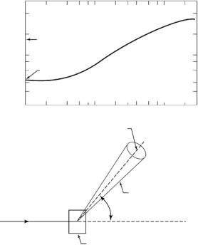
Figure 8.1 dramatically shows that the total (σ) scattering cross-section (scattering plus absorption) of a light water molecule (H2O) is a strong function of the energy of the incident neutrons (E0). For high E0, the energies associated with the vibrational and translational motion of water molecules are negligible and the cross-section approaches the sum of the free atom cross-sections for the hydrogen and oxygen atoms (σFREE 44 × 10−24 cm2 or 44 barns). However, as E0 → 0, the scattering does not plateau at the bound atom cross-section ( 167 barns) and varies continuously with energy. This variation is due mainly to inelastic processes a ecting the incoherent scattering which is the main component of the cross-section. Also, because of inelastic e ects due to torsion, rotation, and vibration, the e ective 1H incoherent cross-section is also a function of the particular chemical group (methyl, hydroxyl, etc.) in which the proton is situated [21]. The total 1H atom cross-section is dominated by the incoherent component (σinc), and hence is a strong function of λ (Fig. 8.1) and only approaches 80 barns at λ 4.5 ˚A [9].
8 SANS from Biological Molecules |
133 |
σ (BARNS)
400
200
Bound atom cross section, σs for H2O molecule
100
80
60 σFree
40
30
20 |
|
|
|
|
|
|
|
|
|
0.1 |
0.2 |
0.4 |
0.6 |
1 |
2 |
4 |
6 |
8 |
10 |
|
|
|
|
|
λ (Å) |
|
|
|
|
SOLID ANGLE dΩ
DETECTOR
SCATTERED NEUTRON
BEAM, ENERGY, E1
INCIDENT NEUTRON |
2θ |
|
|
BEAM, ENERGY, E0 |
|
SAMPLE
Fig. 8.1. Total cross-section for water molecule (H2O) vs. neutron wavelength at T = 293 K according to Brookhaven National Laboratory Tables (top) The basic scattering experiment (bottom)
There is a large di erence in the coherent scattering length between deuterium (bD = 0.667 × 10⁻¹² cm) and hydrogen (bH = −0.374 × 10⁻¹² cm) and the latter value is actually negative. This arises from a change of phase of the scattered wave and results in a marked di erence in scattering power (contrast) between molecules labeled with deuterium or hydrogen, or suspended in light–heavy water. The basic experiment [9] consists of an incident neutron beam (wavelength, λ), which is scattered by an assembly of nuclei through an angle φ = 2θ into a solid angle dΩ (Fig. 8.1), and for both SANS and SAXS it is assumed that any change in energy on scattering is small compared to the incident energy, E0. The coherent component of the scattering contains information on the correlations between di erent nuclei [9] and hence reflects the relative spatial arrangement of atoms in the system (e.g., the structure). Thus, the angular or Q-dependence of the scattering is related inversely, via a Fourier transform, to the spatial variation of the structure Eq. 8.3.
In principle, the incoherent cross-section contains information on the correlations between the same nucleus and hence gives information on the time dependence of the position of an individual atom (e.g., vibration, di usion,
134 J.K. Krueger et al.
etc.). However, extracting such information would require an energy analysis of the scattered beam, which has not hitherto been performed for the vast majority of SANS experiments. These are conventionally undertaken by integrating the scattered neutrons over all energies, so information on the time dependence of the structure is not normally obtained in practice, and the incoherent component of the cross-section forms an isotropic (flat) background which must be subtracted o in SANS structural investigations. This signal arises from nuclei with nonzero spin (e.g., hydrogen) and due to multiple scattering, e ects, this background is a function of the sample dimensions, transmission, etc. and thus cannot be expressed as a true cross-section [22,23]. However, it is usually smaller than the coherent signal and may be subtracted o to good accuracy by empirical methods [24].
8.2.2 Scattering Length Density
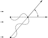
In general, radiation incident on a medium whose scattering power is independent of position is scattered only into the forward direction (φ = 2θ = 0). For every volume element (S) which scatters through an angle φ = 2θ > 0,
there is another volume element (S ) which |
scatters exactly (180◦) out |
of phase, (see Fig. 8.2 where P S − S S = |
λ/2). Therefore, all scatter- |
ing cancels unless the scattering power is di erent at S and S , i.e., fluctuates from point-to-point in the sample. X-rays and light photons interact with electrons in the sample and hence are scattered by fluctuations in electron density. Neutrons do not interact with electrons (apart from unpaired spins, where the interaction arises from the magnetic moment of such elements as rare earths, transition metal, etc.). In general, biopoly-
mers and solvents do not contain such |
elements, so the only interaction |
|||
is via nuclear scattering. Because each |
nucleus has a di erent scattering |
|||
|
|
|
|
SCATTERED DIRECTION |
INCIDENT |
PS - S'S = |
l |
|
|
2 |
|
|||
|
|
|
|
2q |
P |
|
S |
INCIDENT |
|
RADIATION |
|
|
|
DIRCTION |
|
|
|
|
|
WAVEFRONT |
MOMENTUM TRANSFER: Q = 4p sin q |
|||
|
|
|
|
l |
WAVELENGHT (l) |
DISTANCE SCALE PROBED: D~− 2π |
|||
|
|
|
|
Q |
S' |
COMBINE TO GIVE BRAGG'S LAW: l = 2D sin q |
|||
Fig. 8.2. For every point S which scatters radiation through an angle 2θ > 0, there is another point S , which scatters radiation exactly 180◦ out of phase. Therefore, all scattering cancels unless the scattering power is di erent at S and S , i.e., fluctuates from point to point in the sample
8 SANS from Biological Molecules |
135 |
amplitude, the scattering length density (SLD) is defined as the sum of coherent scattering lengths over all atoms lying in a given volume, V , divided by V [9, 23]. Table 1.2 in the contribution by Harroun et al. this volume gives representative values of the scattering lengths and volumes of some common amino acids and proteins. The SLD is the ratio of these quantities and is typically in the range 1.4–5.4 × 1010 cm−2, though the actual volumes (and hence the associated SLDs) are not universal constants and di er according to conditions (e.g., solvent, salt concentration, environment, etc.). For a discussion of such e ects, see D. Svergun et al. [29]. For X-rays or light, the (photon) SLD is the electron density multiplied by the Thompson scattering factor of one electron, rT = 0.282 × 10⁻¹² cm [23, 26].
8.2.3 Contrast Variation
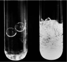
Contrast variation methods have found wide application in structural biology, where they can be used to distinguish the scattering due to individual components within a macromolecular complex; provided the components have di erent neutron scattering densities. In the case of a multiprotein complex, selective deuteration of an individual protein component provides an approach to selectively altering that component’s neutron scattering density. Subsequently, by changing the deuterium level in the solvent, the neutron scattering contrast of each component is varied. Under certain conditions where the mean solvent density matches that of one of the components, the solvent matched component becomes “invisible” in the neutron experiment and any measured scattering intensity is due primarily to the non solvent-matched component. The concepts underlying solvent matching are most easily demonstrated by an equivalent experiment with visible light, illustrated in Fig. 8.3, made by D.M. Engelman (Yale University). Both tubes contain two Pyrex beads embedded in (borosilicate) glass wool, which has a di erent refractive index to the beads. When light shines on the tube at right, both the beads and glass wool scatter light, but only the glass wool can be seen because it dominates the scattering. In order to observe the beads, the tube on the left has been filled with a solvent which has the same refractive index as the glass wool. Thus, the electron density and hence the scattering power of the glass wool has been matched with that of the solvent, thus eliminating this component of the scattering and making the wool transparent to light.
This principle can be used in SANS experiments via isotopic solvent mixtures (e.g., H2O–D2O), as light water (H2O) has an SLD of −0.562×1010 cm−2 (or −0.00562 × 10⁻¹² cm ˚A−3) while that of heavy water (D2O) is 6.404 × 1010 cm−2 (or 0.06404 × 10⁻¹² cm ˚A−3), so the SLD of a mixture is a linear function of the percentage of D2O and is zero for 8 vol% D2O. Because of proton exchange, the SLD of a biological unit (e.g., protein) will vary even if it is not specifically deuterated at nonexchangeable position, by immersion in a solvent containing D2O, and is therefore a function of the H2O–D2O ratio.
136 J.K. Krueger et al.
AB
Fig. 8.3. Two tubes containing Pyrex beads in glass wool and solvent: (A) Refractive index of solvent matches that of glass wool. (B) Refractive index of solvent is di erent to that of glass wool or Pyrex beads and scattering from the glass wool dominates (reproduced with permission of D.M. Engelman)
Solvent matching thus provides a means for extracting structural information on the individual components within a complex. The e ectiveness of the solvent matching experiment depends upon having uniform density components such that the internal density fluctuations can be ignored, as well as on very precise matching of the component and the solvent densities, which can be tricky.
A more robust approach to utilizing contrast variation methods with neutron scattering for extracting structural information from macromolecular complexes is to measure a “contrast series” in which the solvent deuteration level is systematically varied over the widest range possible. For a complex of two components with di erent mean neutron SLD, the total scattering can be written as:
I(Q, ∆ρ |
A |
, ∆ρ |
) = ∆ρ2 I |
A |
(Q) + ∆ρ |
A |
∆ρ I |
AB |
(Q) + ∆ρ2 I |
(Q). (8.5) |
|
B |
A |
|
B |
B B |
|
The subscripts A and B refer to each component and ∆ρX = ρX − ρS where ρX is the mean SLD for the individual components (A or B) and ρS is the mean SLD for the solvent. Equation 8.5 assumes the di erence between mean scattering densities for the individual components is much greater than any internal density fluctuations within each component. The three terms in Eq. 8.5 correspond to the three basic scattering f unctions. IA(Q) and IB(Q) represent the scattering of components A and B, respectively, while IAB(Q) is the cross-term which is due to interparticle scattering thus its inverse Fourier transform (IFT) provides information about vector distances between the two scattering particles and the first moment of this transform gives the separation of the centers-of-mass. A set of neutron scattering measurements with di erent D2O:H2O ratios in the solvent gives a set of equations in the form of Eq. 8.5
8 SANS from Biological Molecules |
137 |
which can be solved to give the three basic scattering functions from which one can derive the structural parameters for each component as well as information on their relative dispositions. Contrast variation using neutrons for studies of biological molecules was demonstrated by Ibel and Stuhrmann [27] and there are number of excellent reviews on the topic [18, 28–31]. Specific examples on the use of both solvent matching as well as contrast variation to obtain unique information will be presented for SANS structural studies of protein/protein complexes at the end of this paper.
8.3 Practical Aspects of SANS Experiments
and Data Analysis
8.3.1 SANS Instrumentation
The first instrument [32, 33] suitable for the study of biopolymers was built in the early 1970s at the FRJ2 reactor at the Forschungszentrum J¨ulich, Germany, and pioneered the use of long wavelength neutrons and large overall instrument length (> 20 m). It was also the first to boost the flux of the long wavelength (λ > 5 ˚A) or “cold neutron” component of the Maxwellian spectrum by moderating the neutrons to a lower temperature by means of a cold source containing a small volume of liquid hydrogen at T 20 K. This gives flux gains of over an order of magnitude at λ 10 ˚A, and it was on this instrument that the initial SANS experiments on biopolymers were performed. The D11 facility, built on the High Flux Reactor (HFR) at the Institut LaueLangevin (ILL), Grenoble, France, incorporated many of the features of the FRJ2 instrument, including a cold source and long ( 80 m) dimensions [34]. The FRJ2 and HFR facilities have both been subsequently upgraded [35, 36] and expanded to be among the most productive SANS facilities worldwide. At the time of writing, the most e ective SANS facilities for biological studies in the US are at the National Institute for Standards and Technology (NIST) [37].
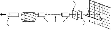
Currently, over 30 SANS instruments are now in operation or under construction worldwide, most of which are reactor based, and a schematic diagram is shown in Fig. 8.4. Fission neutrons are produced in the core, which is surrounded by a moderator (e.g., D2O, H2O) and reflector (e.g., Be, graphite) which reduce the neutron energy. Because of the λ−4 factor which enters into the calculation [33] of the scattering power for a given resolution (∆Q/Q), it is highly advantageous to use long wavelengths and to increase the flux in this region. This may be accomplished by further moderating the neutrons to a lower temperature by means of a cold source containing a small volume of liquid or superfluid hydrogen, placed near the end of the beam tube. The neutrons are transported from the source to the instrument by neutron guide tubes. These are often coated by natural Ni or isotopic 58Ni, and operated by total internal reflection to transport the neutron beam from the cold source to
138 J.K. Krueger et al.
|
|
Beam-defining |
Area detector |
|
|
aperature |
|
|
|
|
|
To |
Velocity |
|
2θ |
reactor |
selector |
|
|
Fixed neutron
Moveable neutron Sample
guides
guides
Scattered
Q
beamx
Fig. 8.4. Schematic of a reactor-based SANS facility
the sample, in a manner analogous to the way that light may be transported by fiber optics. The guide system (Fig. 8.4) provides a gap for the insertion of a velocity selector to define the wavelength (5 < λ < 30 ˚A) and bandwidth (∆λ/λ 5–35%) of the neutron beam. In addition to fixed neutron guides, most instruments have translatable guide sections and apertures that may be moved in and out of the neutron beam to define the incident beam collimation. This is followed by an accessible section (1 – 2 m) at the sample position to accommodate temperature-controlled sample changers, flow cells, etc. Thus, when all the moveable guides are removed from the beam, the source slit is typically 10 – 20 m from the sample, and this distance is reduced to 1 – 2 m, when all the guides are translated into the beam to increase the sample flux. An area detector (typically a 64 × 64 cm2 or 100 × 100 cm2 proportional counter) is often positioned via a motor-driven carrier mounted on rails [32–38] in the post-sample flight-tube, 1 – 20 m in length. Like the incident neutron guides, this is normally evacuated to reduce air scatter, which would otherwise be strong, given overall instrument lengths 20–40 m.
The majority of area detectors are multiwire proportional counters [34,39], with active areas up to 1 m2, and an element (cell) size 0.5 – 1 cm2, which is chosen to be of the same order as the sample size to equalize the various contributions to the instrumental resolution [33, 34]. In general, the detector response function, R(Q), is Gaussian with a full width at half maximum 0.5 – 1 cm and the spatial variation of the detector e ciency ( ) is usually measured via an incoherent scatterer (e.g., light water), which has an angle-independent intensity in the Q-range measured [23, 40].
Reactor sources also produce appreciable background (e.g., fast neutrons, γ-rays). By introducing some curvature into the guides, it is possible to separate out this component, which is not reflected as e ciently as cold (λ 5
– 30 ˚A) neutrons. Alternatively, the beam may be deflected by supermirrors [41, 43] and such mirrors may be designed to reflect up to 3 – 4 times the critical angle for internal reflection that can be achieved by natural Ni guide coatings (θc = 0.1λ (˚A)).
The size of the beam at the sample is defined by slits (irises) made of neutron absorbing materials (e.g., Li6, cadmium, boron), for which the ratio
8 SANS from Biological Molecules |
139 |
of scattering to absorption is virtually zero. This has the result that neutron beams can be very well collimated [10,32] and the ratio of parasitic scattering to the main beam intensity is very small (typically <10−5 within 1 mm from the beam stop). For X-rays on the other hand, materials which have high absorption (to define an SAXS beam) also have high scattering power, as both parameters are a strong function of the atomic number, and parasitic scattering is usually higher for SAXS.
At the time of writing there are over 40 neutron sources around the world operating as user facilities [42]. Of these sources, 36 are reactor facilities, the majority of them are commissioned more than 30-years ago and consequently now have increasingly finite lifetimes. A forward survey [43] estimated that over the next two decades, the installed capacity of neutron beams for research could decrease substantially. Fortunately, the expected decline in the availability of reactor-based SANS instruments has been o set by two competing trends. First, several new reactors are under construction worldwide [44], along with upgrades to existing sources (e.g., at the ILL in the mid1990s, NIST during 1995–2002 and Oak Ridge National Laboratory during 2000–2006). In addition, a range of accelerator-based SANS instruments have been developed over the past 15-years, and in particular, a “next generation” Spallation Neutron Source is under construction at Oak Ridge [45] and at Tokai-mura [46]. Similarly, the second target station for the ISIS-pulsed facility [47], currently under construction, and a proposed [48] European Spallation Source will do much to assure the availability of SANS facilities in the future.
The spallation process involves bombarding a heavy metal (e.g., Ta, W, or Hg) target with high-energy protons, thus placing those nuclei into a highly excited state. These lose energy by “evaporating” nuclei, and in the case of a tungsten target, each proton results in the production of 15 neutrons. The protons are usually accelerated in pulses and so neutron production also occurs in pulses, which allows the use of time-of-flight (TOF) techniques. Shorter wavelength neutrons travel faster and arrive at a detector earlier than longer wavelength neutrons, so there is thus no need to employ a velocity selector to monochromate the incident beam. Another benefit of the TOF approach is that any given point on a detector corresponds to several di erent Q values, determined by the wavelength of the neutrons arriving there. Hence, a greater the range of Q values can be measured with any given configuration of [49] instrument. Pulsed-source SANS instruments therefore have a greater dynamic range in Q than reactor-source instruments, though the latter can be increased by moving the detector “o axis” [37, 50].
As the main applications of the SANS technique have been undertaken on reactor sources, these instruments have been optimized over the past several decades, and the flux of instruments planned on new or upgraded reactor sources will either be less than or equal to the current state of the art instruments (e.g., the D22 instrument at the ILL [50]). However, this is not the case for pulsed facilities, which have not yet begun to reach their full potential so

140 J.K. Krueger et al.
we can still expect order of magnitude gains over the current facilities. Thus, it seems likely that pulsed sources will make a greater contribution to SANS studies of biopolymers in future than they have in the past.
8.3.2 The Importance of Absolute Calibration
and Having Well-Characterized Samples
This section will emphasize the importance of placing intensity data on an absolute scale, typically in the form of a di erential scattering cross-section dΣ/dΩ(Q), in units of cm−1. While the use of absolute units is not essential for the measurement of the spatial dimensions (e.g., determining the radius of gyration, Rg, of a molecule or particle), it forms a valuable diagnostic tool for the detection of artifacts to which scattering techniques are often vulnerable [23]. Because the cross-section varies as the sixth power of the dimensions [51], it is a sensitive indicator of whether an appropriate structural model has been chosen. For example, SANS studies of colloidal solutions may be modeled by core–shell spherical micelles as a function of a set of parameters describing the particle structure and interactions [52]. On an arbitrary intensity scale, Hayter and Penfold have pointed out that it is possible to produce excellent fits of the particle shape, which may be in error by as much as 3–4 orders of magnitude in intensity [53]. Thus, absolute calibration allows such artifacts to be recognized, and the model parameters may be restricted to those, which reproduce the observed cross-section.
In view of the maturity of the SANS technique, it is surprising that data are still published in arbitrary units which are functions of the time scale of the experiment and/or the sample dimensions (e.g., thickness). Conversion to an absolute scale may be accomplished by multiplying by a calibration constant and the absolute cross-section [dΣ/dΩ(Q)], is defined [54] as the ratio of the number of neutrons (neutrons s−1) scattered per second into unit solid angle divided by the incident neutron flux (neutrons cm−2 s−1) and thus has the dimensions of area (cm2). On normalizing to unit sample volume, dΣ/dΩ(Q) has units of cm−1. For all systems discussed in this chapter, the scattering is azimuthally symmetric about the incident beam, i.e., dΣ/dΩ(Q) is a function only of the magnitude of the scattering vector |Q| = 4πλ−1 sin θ. Thus, the relationship between the cross-section and the measured intensity or count rate I(Q) (counts s−1) in a detector element with area, ∆a, and counting e ciency, , situated normal to the scattered beam at a distance, r, from the sample, is given by
dΣ/dΩ(Q) = |
I(Q)r2 |
(8.6) |
I0∆aAtT , |
where I0 is the intensity (counts s−1 cm−2) on a sample of area A, thickness t, and irradiated volume = At. The measured transmission T is given by T = e− t where µ is the linear attenuation coe cient and accounts for
8 SANS from Biological Molecules |
141 |
the attenuation of the beam on passing through the sample. For SANS it is assumed that the attenuation factor is the same for all scattered neutrons and this approximation is reasonable for φ = 2θ < 10◦. Similarly, Eq. 8.6 assumes that the solid angle subtended by a detector element is independent of 2θ and this approximation again holds for small angles where cos 2θ is close to unity. Since the time dimension cancels in both the numerator and denominator of Eq. 8.6, absolute calibration reduces to measuring the constant KN = I0∆a, which may be determined by comparison with a standard of known crosssection, run in the same scattering geometry for the same time. If an incident beam intensity monitor is employed, as is normally the case, comparisons are made for the same number of monitor counts, i.e., the same number of incident neutrons. Various calibration measurements have been used to measure the calibration constant, both for SANS [22, 55, 56] and SAXS [57], including direct measurement of the beam flux, calibration via a predominantly incoherently scattering material (e.g., vanadium or water) and various other standards.
Specific factors that must be considered in SANS calibrations have been discussed [9] and in particular, multiple scattering and sample preparation are important when using vanadium, which has virtually no coherent crosssection. One disadvantage of this standard is that the cross-section is low and also isotropic, so the run times for calibration are relatively long. Due to limited beam-time allocations, arising from the high demand for SANS facilities, users are naturally reluctant to devote a significant fraction of their instrument time for calibration runs. For this reason, it has been a matter of policy at many SANS facilities, to provide strongly scattering precalibrated samples to allow users to perform absolute scaling with brief calibration runs, which do not detract significantly from the available beam time. The scattering from light water (H2O) is predominantly incoherent and because the absorption cross-section is small, this system has the advantage of much higher intrinsic scattering for calibration purposes [55, 58], and hence has lower sensitivity to statistical errors and artifacts than vanadium. One disadvantage is that, for 1–2 mm samples, the multiple scattering is much higher (>30% than for vanadium ( 10%) and cannot be calculated to the same degree of accuracy [22], because an appreciable fraction of neutrons are scattered inelastically. Such effects are very di cult to model [59–61] and moreover, the detector e ciency is a function of the wavelength and this introduces sample-dependent and instrument-dependent factors, depending on how a given detector responds to the inelastically scattered neutrons [59]. The use of Eq. 8.6 would lead to apparent cross-sections, which are functions of wavelength and are also detector dependent. Also, because of the strong multiple scattering, the intensity for water or protonated (1H-labeled) polymer samples is not proportional to the product, tT , as in Eq. 8.6, and hence it is not possible to define a true cross-section which is a material (intensive) property, independent of the sample dimensions. The scattering is a nonlinear function of the thickness, though such samples may still be used for calibration, provided the thickness is