

Component replacement procedures
This chapter provides removal and replacement procedures.
There are as many as 72 screws that must be removed, replaced, and/or loosened when servicing the computer. Make special note of each screw size and location during removal and replacement.
Service tag
When ordering parts or requesting information, provide the computer serial number and model number provided on the service tag. It is necessary to remove the battery to obtain these numbers. See Battery on page 35 for battery removal instructions.
Item |
Component |
Description |
|
|
|
(1) |
Product name |
This is the product name affixed to the front of |
|
|
the computer. |
|
|
|
(2) |
Serial number (s/n) |
This is an alphanumeric identifier that is unique to |
|
|
each product. |
|
|
|
(3) |
Part number/Product number (p/n) |
This number provides specific information about |
|
|
the product’s hardware components. The part number |
|
|
helps a service technician determine what components |
|
|
and parts are needed. |
|
|
|
Component replacement procedures |
33 |

Item |
Component |
Description |
|
|
|
(4) |
Warranty period |
This number describes the duration of the warranty |
|
|
period for the computer. |
|
|
|
(5) |
Model description |
This is the alphanumeric identifier used to locate |
|
|
documents, drivers, and support for the computer. |
|
|
|
Computer feet
The computer feet are adhesive-backed rubber pads. There are 4 rubber feet that attach to
the base enclosure, as indicated in the illustration below. These rubber feet are available in the Rubber Kit, spare part number 686276-001.
34 |
Chapter 4 Removal and replacement procedures |
Battery
Description |
Spare part number |
|
|
6-cell, 55-Wh, 2.55-Ah, Li-ion battery |
593554-001 |
|
|
6-cell, 47-Wh, 2.20-Ah, Li-ion battery |
593553-001 |
|
|
 IMPORTANT: The customer should not attempt to replace the computer battery, which is installed and sealed at the factory. A broken battery seal voids the computer and battery warranties. The computer has an internal rechargeable battery that can be replaced only by an authorized service provider.
Before disassembling the computer, follow these steps:
1.Turn off the computer. If you are unsure whether the computer is off or in Hibernation, turn the computer on, and then shut it down through the operating system.
2.Disconnect the power from the computer by unplugging the power cord from the computer.
3.Disconnect all external devices from the computer.
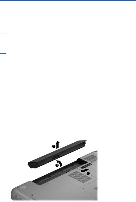
Remove the battery:
1.Turn the computer upside down on a flat surface.
2.Slide the battery release latch (1) to release the battery.
3.Pivot the front edge of the battery (2) up and back.
4.Remove the battery (3) from the computer.
To insert the battery:
1.Align the tabs on the rear edge of the battery with the notches on the rear edge of the battery bay.
2.Pivot the front edge of the battery down into the battery bay until it is seated. (The battery release latch will automatically lock into place.)
Component replacement procedures |
35 |
Memory module
Description |
Spare part number |
|
|
4-GB memory module (PC3, 12800, 1600-MHz) |
652972-001 |
|
|
2-GB memory module (PC3, 12800, 1600-MHz) |
641369-001 |
|
|
Before removing the memory module, follow these steps:
1.Turn off the computer. If you are unsure whether the computer is off or in Hibernation, turn the computer on, and then shut it down through the operating system.
2.Disconnect the power from the computer by unplugging the power cord from the computer.
3.Disconnect all external devices from the computer.
4.Remove the battery (see Battery on page 35).
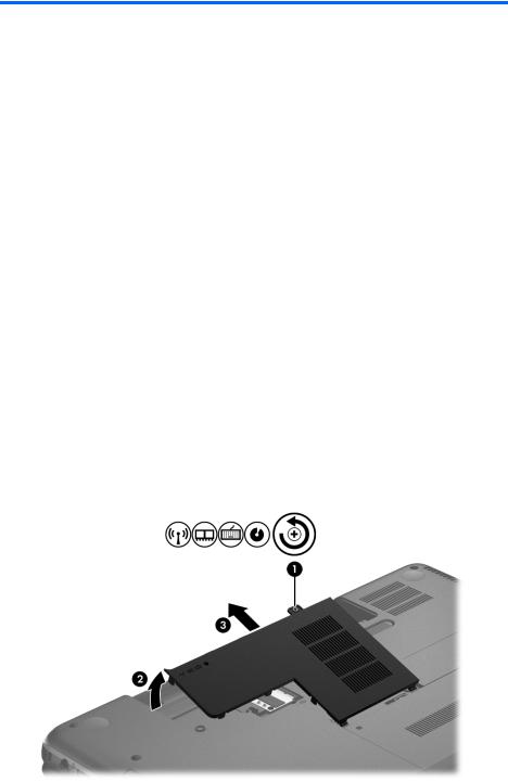
Remove the memory module:
1.Loosen the captive screw (1) that secures the memory module/wireless module compartment cover to the computer.
2.Lift the rear edge of the memory module/wireless module compartment cover (2) up and forward until it rests at an angle.
3.Remove the memory module/wireless module compartment cover (3) by sliding it away from the computer at an angle. The memory module/wireless module compartment cover is available in the Cover Kit, spare part number 686272-001.
4.Spread the retaining tabs (1) on each side of the memory module slot to release the memory module. (The memory module tilts up.)
36 |
Chapter 4 Removal and replacement procedures |