

Optical drive
Description |
Spare part number |
|
|
DVD±RW Double-Layer with SuperMulti Drive (includes optical drive bezel and optical |
686268-001 |
drive bracket) |
|
|
|
Before removing the optical drive, follow these steps:
1.Turn off the computer. If you are unsure whether the computer is off or in Hibernation, turn the computer on, and then shut it down through the operating system.
2.Disconnect the power from the computer by unplugging the power cord from the computer.
3.Disconnect all external devices from the computer.
4.Remove the battery (see Battery on page 35).
5.Remove the memory module/wireless module compartment cover (see Memory module on page 36).
Remove the optical drive:
1.Remove the Phillips PM2.5×4.0 screw (1) that secures the optical drive to the computer.
2.Use a flat-blade screw driver or similar tool to press on the optical drive bracket tab (2) to release the optical drive.
3.Remove the optical drive (3) from the computer.
Component replacement procedures |
43 |
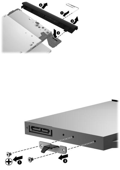
4.If it is necessary to replace the optical drive bezel, use a thin tool or an unbent paper clip (1) to release the optical drive tray.
5.Use a flat-blade screw driver or similar tool to press on the optical drive bezel tab (2) to release the optical drive bezel.
6.Release the left side of the optical drive bezel (3).
7.Remove the optical drive bezel (4).
8.If it is necessary to replace the optical drive bracket, position the optical drive with the rear panel toward you.
9.Remove the two Phillips PM2.0×3.0 screws (1) that secure the optical drive bracket to the optical drive.
10.Remove the optical drive bracket (2).
Reverse this procedure to install the optical drive.
44 |
Chapter 4 Removal and replacement procedures |

Hard drive
 NOTE: The hard drive spare part kit does not include the hard drive bracket, hard drive connector cable, or screws.
Description |
Spare part number |
|
|
640-GB, 5400-rpm, 9.5-mm |
669300-001 |
|
|
500-GB, 5400-rpm, 9.5-mm |
669299-001 |
|
|
320-GB, 5400-rpm, 9.5-mm |
622643-001 |
|
|
Hard Drive Hardware Kit (includes hard drive bracket, hard drive connector cable, and screws) |
686261-001 |
|
|
Before removing the hard drive, follow these steps:
1.Turn off the computer. If you are unsure whether the computer is off or in Hibernation, turn the computer on, and then shut it down through the operating system.
2.Disconnect the power from the computer by unplugging the power cord from the computer.
3.Disconnect all external devices from the computer.
4.Remove the battery (see Battery on page 35).
5.Remove the memory module/wireless module compartment cover (see Memory module on page 36).
Remove the hard drive:
1.Loosen the captive screw (1) that secures the hard drive compartment cover to the computer.
2.Lift the rear edge of the hard drive compartment cover (2) up and forward until it rests at an angle.
Component replacement procedures |
45 |
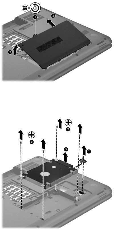
3.Remove the hard drive compartment cover (3) by sliding it away from the computer at an angle. The hard drive compartment cover is available in the Cover Kit, spare part number 686272-001.
4.Disconnect the hard drive connector cable (1) from the system board, and then release the cable from the clip (2) built into the base enclosure.
5.Remove the four Phillips PM2.5×4.0 screws (3) that secure the hard drive to the computer.
6.Remove the hard drive (4) from the hard drive bay.
46 |
Chapter 4 Removal and replacement procedures |
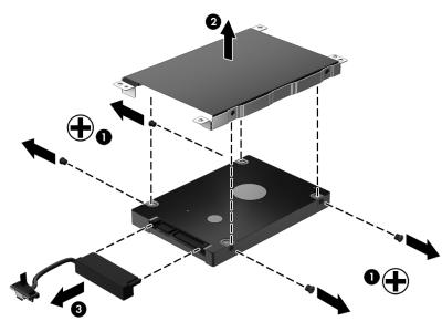
7.If it is necessary to disassemble the hard drive, perform the following steps:
a.Remove the four Phillips PM3.0×3.0 screws (1) that secure the hard drive bracket to the hard drive.
b.Remove the hard drive bracket (2) from the hard drive.
c.Disconnect the hard drive connector cable (3) from the hard drive. The hard drive bracket, hard drive connector cable, and screws are available in the Hard Drive Hardware Kit, spare part number 686261-001.
Reverse this procedure to reassemble and install the hard drive.
Component replacement procedures |
47 |