

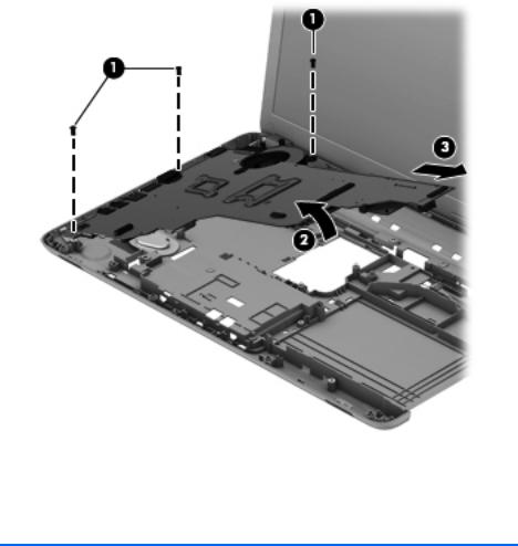
4.Remove the system board (3) by sliding it up and to the right at an angle.
Reverse this procedure to install the system board.
Fan/heat sink assembly
Description |
Spare part number |
|
|
Fan/heat assembly (includes replacement thermal material) |
688306-001 |
|
|
Before removing the fan/heat sink assembly, follow these steps:
1.Turn off the computer. If you are unsure whether the computer is off or in Hibernation, turn the computer on, and then shut it down through the operating system.
2.Disconnect the power from the computer by unplugging the power cord from the computer.
3.Disconnect all external devices from the computer.
4.Remove the battery (see Battery on page 35), and then remove the following components:
a.Memory module/wireless module compartment cover (see Memory module on page 36)
b.Keyboard (see Keyboard on page 39)
c.Hard drive (see Hard drive on page 45)
64 |
Chapter 4 Removal and replacement procedures |

d.Top cover (see Top cover on page 49)
e.System board (see System board on page 62) Remove the fan/heat sink assembly:
1.Turn the system board upside down, with the front toward you.
2.Disconnect the fan cable (1) from the system board.
3.Following the 1, 2, 3, 4 sequence stamped into the heat sink, loosen the four captive Philllips screws (2) that secure the fan/heat sink assembly to the system board.
4.Remove the fan/heat sink assembly (3).
 NOTE: Due to the adhesive quality of the thermal material located between the processor heat sink and processor, it may be necessary to move the processor heat sink from side to side to detach it.
The thermal material must be thoroughly cleaned from the surfaces of the processor heat sink and
the processor each time the processor heat sink is removed. Replacement thermal material is included with the processor heat sink and system board spare part kits.
 NOTE: The following illustration shows the replacement thermal material locations. Thermal paste is used on the processor (1) and the heat sink section (2) that services it.
Component replacement procedures |
65 |

Reverse this procedure to install the fan/heat sink assembly.
66 |
Chapter 4 Removal and replacement procedures |

Display assembly
 NOTE: The display assembly is spared at the subcomponent level only. For more display assembly spare part information, see the individual removal subsections.
Before removing the display assembly, follow these steps:
1.Turn off the computer. If you are unsure whether the computer is off or in Hibernation, turn the computer on, and then shut it down through the operating system.
2.Disconnect the power from the computer by unplugging the power cord from the computer.
3.Disconnect all external devices from the computer.
4.Remove the battery (see Battery on page 35).
5.Disconnect the wireless antenna cables from the WLAN module (see Memory module on page 36).
6.Remove the following components:
a.Keyboard (see Keyboard on page 39)
b.Hard drive (see Hard drive on page 45)
c.Top cover (see Top cover on page 49)
Remove the display assembly:
1.Disconnect the display panel cable (1) from the system board.
Component replacement procedures |
67 |

2.Release the wireless antenna cables (2) from the clips and routing channel built into the base enclosure.
 CAUTION: Support the display assembly when removing the following screws. Failure to support the display assembly can result in damage to the display assembly and other computer components.
3.Remove the five Phillips PM2.5×6.5 screws (1) that secure the display assembly to the base enclosure.
68 |
Chapter 4 Removal and replacement procedures |

4.Remove the display assembly (2).
5.If it is necessary to replace the display bezel or any of the display assembly subcomponents:
a.Remove the two display bezel screw covers (1) and the two Phillips PM2.5×5.5 screws (2) that secure the display bezel to the display assembly. The display bezel screw covers are available in the Rubber Kit, spare part number 686276-001.
b.Flex the inside edges of the bottom edge (3), the left and right sides (4), and the
top edge (5) of the display bezel until the bezel disengages from the display enclosure.
Component replacement procedures |
69 |

c.Remove the display bezel (6). The display bezel is available using spare part number 686254-001.
6.If it is necessary to replace the display hinge covers:
a.Remove the two Phillips PM2.5×4.0 screws (1) that secure the display hinge covers to the display enclosure.
b.Remove the display hinge covers (2). The display hinge covers are available using spare part number 686262-001.
70 |
Chapter 4 Removal and replacement procedures |

7.If it is necessary to replace the display panel:
a.Release the display panel cable (1) from the clips built into the bottom edge of the display enclosure.
b.Remove the four Phillips PM2.5×4.0 screws (2) that secure the display panel to the display enclosure.
c.Lift the top edge of the display panel (3), and then swing it up and forward until it rests upside down in front of the display enclosure.
d.Release the adhesive support strip (1) that secures the display panel cable to the display panel.
e.Detach the display panel cable (2) from the display panel. (The display panel cable is attached to the display panel with double-sided tape.)
Component replacement procedures |
71 |

f.Disconnect the display panel cable (3) from the display panel.
g.Remove the display panel. The display panel is available using spare part number 687700-001.
8.If it is necessary to replace the display hinges:
a.Remove the six Phillips PM2.0×3.5 screws (1) that secure the display hinges to the display panel.
72 |
Chapter 4 Removal and replacement procedures |
b.Remove the display hinges (2). The display hinges are available using spare part number 686262-001.
9.If it is necessary to replace the display panel cable:
a.Detach the display panel cable (1) from the display enclosure. (The display panel cable is attached to the display enclosure with double-sided tape in multiple locations.)
b.Disconnect the webcam/microphone cable (2) from the webcam/microphone module.
Component replacement procedures |
73 |
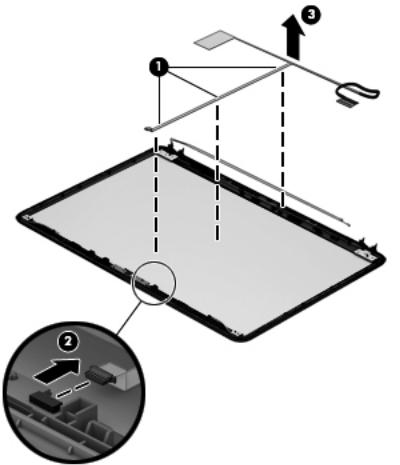
c.Remove the display panel cable (3). The display panel cable is available using spare part number 686256-001 and includes the webcam/microphone cable.
74 |
Chapter 4 Removal and replacement procedures |
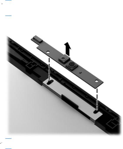
10.If it is necessary to replace the webcam/microphone module, gently detach the webcam/ microphone module from the display enclosure. (The webcam/microphone module is attached to the display enclosure with double-sided tape.) The webcam/microphone module is available using spare part number 686285-001.
 CAUTION: Due to the thin profile of the webcam/microphone module, it is easily damaged. Take extra precaution to ensure the webcam/microphone module is not damaged when removing and replacing the module.
 NOTE: Depending on computer model, some computer models may be equipped one or two sets of wireless antenna cables and transceivers.
11.If it is necessary to replace the wireless antenna cables and transceivers:
a.Detach the wireless antenna transceivers (1) from the display enclosure. (The wireless antenna transceivers are attached to the display enclosure with double-sided tape.)
b.Release the wireless antenna cables from the clips and routing channels along the left, right, and bottom edges of the display enclosure (2).
Component replacement procedures |
75 |