

5.Remove the memory module (2) by pulling it away from the slot at an angle.
Reverse this procedure to install a memory module.
WLAN module
Description |
Spare part number |
|
|
Atheros AR9565 802.11b/g/n 1×1 WiFi + BT4.0 Combo Adapter |
690019-001 |
|
|
Atheros HB125 802.11b/g/n 1×1 WLAN module |
675794-001 |
|
|
Atheros 9485GN 802.11b/g/n 1×1 WiFi and 3012 Bluetooth 4.0 Combo Adapter |
655795-001 |
|
|
Broadcom 4313GN 802.11b/g/n 1×1 WiFi and 20702 Bluetooth 4.0 Combo Adapter |
657325-001 |
|
|
Ralink RT5390F 802.11b/g/n 1×1 WLAN module |
670691-001 |
|
|
Ralink RT5390R 802.11bg/n 1×1 WiFi Adapter |
691415-001 |
|
|
Ralink RT3290LE 802.11b/g/n 1×1 WiFi and Bluetooth 4.0 Combo Adapter |
690020-001 |
|
|
 CAUTION: To prevent an unresponsive system, replace the wireless module only with a wireless module authorized for use in the computer by the governmental agency that regulates wireless devices in your country or region. If you replace the module and then receive a warning message, remove the module to restore device functionality, and then contact technical support.
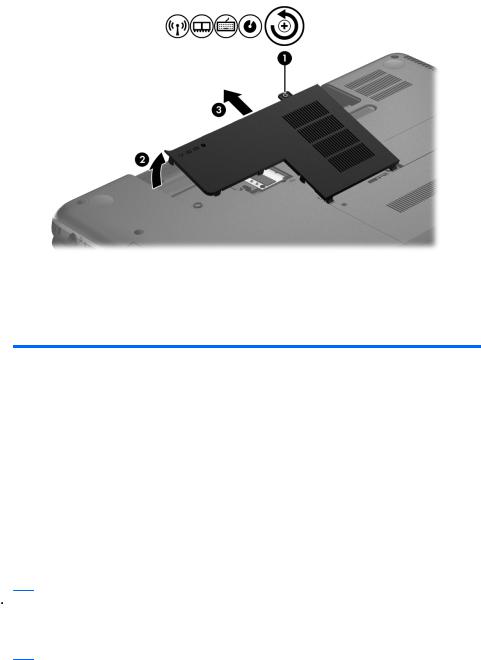
Before removing the WLAN module, follow these steps:
1.Turn off the computer. If you are unsure whether the computer is off or in Hibernation, turn the computer on, and then shut it down through the operating system.
2.Disconnect the power from the computer by unplugging the power cord from the computer.
3.Disconnect all external devices from the computer.
Component replacement procedures |
37 |

4.Remove the battery (see Battery on page 35).
5.Remove the memory module/wireless module compartment cover (see Memory module on page 36).
Remove the WLAN module:
1.Disconnect the WLAN antenna cables (1) from the terminals on the WLAN module.
 NOTE: The #1 WLAN antenna cable is connected to the WLAN module #1 terminal. The #2 WLAN antenna cable is connected to the WLAN module #2 terminal.
2.Remove the Phillips PM2.0×3.0 screw (2) that secures the WLAN module to the system board. (The WLAN module tilts up.)
3.Remove the WLAN module by pulling the module away from the slot at an angle (3).
 NOTE: If the WLAN antennas are not connected to the terminals on the WLAN module, the protective sleeves must be installed on the antenna connectors, as shown in the following illustration.
38 |
Chapter 4 Removal and replacement procedures |

Reverse this procedure to install the WLAN module.
Keyboard
 NOTE: The keyboard spare part kit includes the keyboard cable.
For use in country/region |
Spare part number |
For use in country/region |
Spare part number |
|
|
|
|
For use in Belgium |
646125-A41 |
For use in the Netherlands |
646125-B31 |
|
|
|
|
For use in Bulgaria |
646125-261 |
For use in Portugal |
646125-131 |
|
|
|
|
For use in the Czech Republic |
646125-221 |
For use in Russia |
646125-251 |
|
|
|
|
For use in Denmark, Finland, |
646125-DH1 |
For use in Saudi Arabia |
646125-171 |
and Norway |
|
|
|
|
|
|
|
For use in France |
646125-051 |
For use in Slovenia |
646125-BA1 |
|
|
|
|
For use in Germany |
646125-041 |
For use in Spain |
646125-071 |
|
|
|
|
For use in Greece |
646125-DJ1 |
For use in Switzerland |
646125-BG1 |
|
|
|
|
For use in Hungary |
646125-211 |
For use in Turkey |
646125-141 |
|
|
|
|
For use in Israel |
646125-BB1 |
For use in the United Kingdom |
646125-031 |
|
|
and Singapore |
|
|
|
|
|
For use in Italy |
646125-061 |
|
|
|
|
|
|
Before removing the keyboard, follow these steps:
1.Turn off the computer. If you are unsure whether the computer is off or in Hibernation, turn the computer on, and then shut it down through the operating system.
2.Disconnect the power from the computer by unplugging the power cord from the computer.
3.Disconnect all external devices from the computer.
4.Remove the battery (see Battery on page 35).
5.Remove the memory module/wireless module compartment cover (see Memory module on page 36).
Component replacement procedures |
39 |

Remove the keyboard:
1.Remove the Phillips PM2.5×4.0 screw that secures the keyboard to the computer.
2.Rest and secure the computer on its left side.
3.Partially open the computer.
40 |
Chapter 4 Removal and replacement procedures |
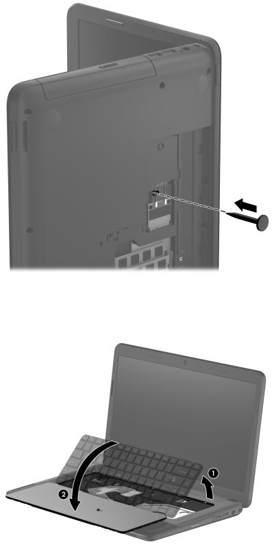
4.Insert a screw driver or similar thin tool into the keyboard release hole, and then press on the back of the keyboard until the keyboard disengages from the computer.
5.Turn the computer right-side up with the front toward you.
6.Lift the rear edge of the keyboard (1), and then swing the keyboard up and forward (2) until it rests upside down on the palm rest.
Component replacement procedures |
41 |

7.Release the zero insertion force (ZIF) connector (1) to which the keyboard cable is attached, and then disconnect the keyboard cable (2) from the system board.
8.Remove the keyboard (3).
Reverse this procedure to install the keyboard.
42 |
Chapter 4 Removal and replacement procedures |