

98 IMMUNOLOGICALLY SENSITIVE FIELD–EFFECT TRANSISTORS
IMMUNOLOGICALLY SENSITIVE FIELD–EFFECT TRANSISTORS
EMMANUEL S. ZACHARIAH
University of New Jersey
New Brunswick, New Jersey
P. GOPALAKRISHNAKONE
National University of Singapore
Singapore
PAVEL NEUZIL
Institute of Bioengineering
and Nanotechnology
Singapore
INTRODUCTION
Diagnostics as a whole represent a large, well-established, and continually expanding market. Methods for the selective determination of analytes in biological fluids, such as blood and urine, are important. When a foreign substance (antigen) invades the human body, the immune system produces antibodies that interact with the antigen. Such a recognizing process involves the formation of an immunocomplex based on interactions between the immunospecies. The recognition is specific for the antibody-antigen system and, thus, for the measurement of antigen concentration (1,2). This determination is of importance for diagnosis because the antigens can be viruses, bacteria that are involved in many human illnesses, such as cancer and AIDS. The analytes detected and measured have also included many other medical diagnostic molecules such as hormones, clinical disease biomarkers, drugs, and environment pollutants such as pesticides. Antibody diversity is so great that virtually any biomolecule can be recognized
(3). The range of analyte concentrations encountered is extremely large, from greater than 10 3 M for species such as glucose and cholesterol and to less than 10 12 M for certain drugs and hormones (4). It is for the detection of these low level analytes that the application of immunological techniques is essential.
An immunoassay is a multistep diagnostic test based on the recognition and binding of the analyte by the antibody. Most immunoassay techniques are based on the separation of free and bound immunospecies (5). In these techniques, one of the immunoagents (antibody or antigen) is immobilized on a solid phase. The solid phase facilitates the separation and washing steps required to differentiate bound and free fractions of the label. Quantification of a bound immunoagent is conducted by using labels covalently bound to the immunoagent with specific properties suitable for detection. The most common labels are radioactive markers, enzymes, and fluorescent labels. For many of the nonisotopic labels, the reagents have been designed such that binding of labeled antigen to antibody in some way modulates the activity of the label, resulting in a homogenous immunoassay without the need for a separation step. The most familiar type of enzyme immunoassay in clinical analysis is known as enzyme-linked immunosorbent assay (ELISA) (6). Different schemes of enzyme immunoassay exist, and, in clinical laboratory practice, the most popular are the ‘‘Sandwich’’ method for large analytes, and compe-
titive binding immunoassay methods for the determination ‘‘haptens’’ (low molecular weight analytes).
The advent of biosensor technology, with the possibility of direct monitoring of immunoreactions, provides opportunity to gain new insight into antigen-antibody reaction kinetics and create rapid assay devices with wider applications. A biosensor is composed of (1) a biochemical receptor, which uses biosubstances such as enzymes, antibodies, or microbes to detect an analyte, (2) a transducer, which transforms changes in physical or chemical value accompanying the reaction into a measurable response, most often in the form of electrical signal (7–9). The term immunosensor is used when antibodies are immobilized to recognize their appropriate antigens (or vice versa) (10). Immunosensors possess several unique features, such as compact size, simplicity of use, one-step reagentless analysis, and absence of radioactivity, which make them attractive alternatives to conventional immunoassay techniques. Immunosensors can be divided, in principle, into two categories: nonlabeled and labeled (11). Nonlabeled or direct-acting immunosensors are designed in a way that the immunocomplex (i.e., the antibody-antigen complex) is directly determined by measuring physical changes induced by the formation of the complex. In contrast, labeled or indirect-sensing immunosensors have incorporated a sensitively detectable label. The immunocomplex is thus entirely determined through measurement of the label. In order to determine an antigen, the corresponding antibody is immobilized on the membrane matrix, which is held on an amperometric-or potentiometric-sensing transducer used to measure the rate of the enzymatic reaction (12–14).
Of the electrochemical technologies for biosensors, the Ion-Sensitive Field Effect Transistor (ISFET) has been the center of special attention as a transducer. ISFETs were introduced by Bergveld in 1970 (15), and were the first type of this class of sensor in which a chemically sensitive layer was integrated with solid-state electronics. A field effect transistor (FET) can be considered as a charge-sensitive device (i.e., any change in the excess interfacial charge at the outer insulator surface will be mirrored by an equal and opposite charge change in the inversion layer of the FET). By excluding the gate metal in a FET and using a pH-sensitive gate insulator, a pHsensitive FET was constructed (16,17). After the invention of the ISFET, many different types of FET-based sensors have been presented. The application of enzymes as the selecting agent in ISFET-based sensing systems leads to the development of highly sensitive sensors. Such enzymemodified ISFETs (EnFETs) can, in principle, be constructed with any enzyme that produces a change in pH on conversion of the concerning substrate (18). By combining the ISFET with a membrane that contains a biological substance, like an antibody, the sensor can detect a specific antigen (19). The ISFET immunosensors or Immunologically sensitive FETs (IMFETs) have several advantages over the conventional enzyme immunoassay. The ISFET could be mass-produced by an integrated circuits (IC) process, which makes it very small and economical. An electric circuit can be integrated on the same chip. The biosensor platform finds many applications in various
IMMUNOLOGICALLY SENSITIVE FIELD–EFFECT TRANSISTORS |
99 |
fields, such as medical diagnostics, fermentation process control, and environmental monitoring.
THEORY
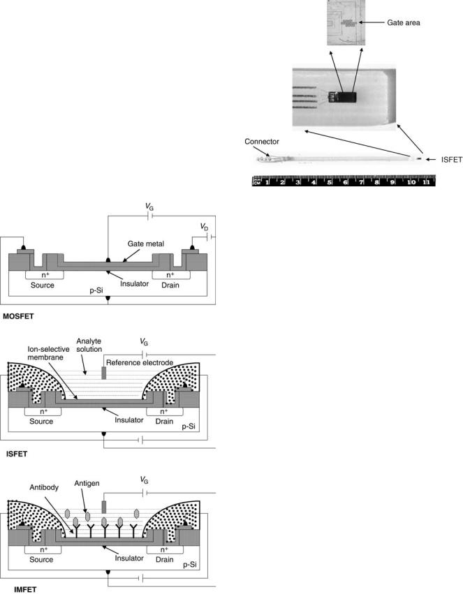
In order to understand the operation of the IMFET, one must trace its origins back to the ISFET or ChemFET (Fig.1). The latter devices have been described in depth elsewhere (20–22). A packaged ISFET is shown in Fig. 2 (23). ISFETs and ChemFETs have, in turn, evolved from the Metal Oxide Semiconductor Field Effect Transistor (MOSFET), currently the most popular active device in the entire semiconductor industry. It is a unipolar device, where the current is given by the flow of majority carriers, either holes in PMOS type or electrons in NMOS type. The operation of the MOSFET can be considered as a resistor controlled by the status of a gate region, so-called MIS structure. It is a sandwich consisting of a stacked-gate
Figure 1. The hierarchy of field effect transistor. a. MOSFET. b. ISFET. c. IMFET.
Figure 2. Photomicrograph of an ISFET device packaged on PCB (23).
metal layer, an insulator (typically silicon oxide), and a semiconductor. Assume a low-level doped p-type (NMOS device). Three different states of charge distribution can occur, depending on the voltage Vg , applied between the metal and a semiconductor. A negative value of Vg causes positive holes to accumulate at the semiconductorinsulator interface. A positive value of Vg of a low magnitude leads to the ‘‘depletion’’ condition in which mobile holes are driven away from the interface, resulting in a negative charge of low density due to the presence of immobile acceptor atoms. Finally, if the Vg exceeds a certain threshold voltage (Vth), electrons accumulate at the semiconductor-insulator interface at a density greater that the hole density, a situation opposite to that normally found with p-type semiconductors. This depletion of mobile charge carriers followed by surface inversion is known as the ‘‘field effect.’’ It forms an electrically conductive channel between two other terminals, a source and a drain (see Figure 1a). The drain current Id through the transistor is a functions of drain and gate voltage. Without surface inversion (i.e., Vg < Vth,) the drain current is negligible, because the drain-to-substrate PN junction is reverse biased.
The MOSFET and its descendants are charge-controlled devices. In analytical applications (e.g., ISFETs, ChemFETs, and IMFETs), the change in charge density is brought about by adsorption of one or more species present in the solution onto the FET structure. In the ISFET, the gate metal is replaced with a conventional reference electrode (Ag/AgCl or Hg/Hg2Cl2), a solution containing an ionic species of interest, and an electroactive material (membrane) capable of selective ion exchange with the analyte (Fig. 1b), which is an example of a nonpolarizable interface, that is, reversible charge transfer occurs between the solution and the membrane. The analyte generates a Nernst potential at the membrane-solution interface, which then modulates the drain current analogous to the manner in which changing the externally applied voltage does for the MOSFET.

100 IMMUNOLOGICALLY SENSITIVE FIELD–EFFECT TRANSISTORS
Direct-Acting (Label-Free) IMFET
The structure of the direct-acting IMFET is similar to that of the ISFET, except that the solution-membrane interface is polarized rather than unpolarized. If the solution-mem- brane interface of the ISFET is ideally polarized (i.e., charge cannot cross the interface), then the ISFET can measure the adsorption of charged species at the interface as shown below. As antibodies, antigens, and proteins are generally electrically charged molecules, the polarized ISFET could be used to monitor their nonspecific adsorption at the solution-membrane interface. To render the polarized ISFET selective for a given antigen and thus create the so-called IMFET, the specific antibody for that antigen has to be immobilized on the surface of the ISFET (see Fig. 1c). The adsorption of this antigen would then be specifically enhanced over other molecules in the solution and the signal measured by the ISFET would be mostly due to the adsorption of that particular antigen. The ISFET interacts with the analyte through an ion-exchange mechanism, whereas the IMFET interaction is based on the antigen-antibody reaction.
This design for the measurement of the adsorption of charged molecules is practicable only if charge cannot cross the interface, which, thus, acts as an ideal capacitor. As will be seen, failure to achieve a perfectly polarizable interface has a detrimental effect on the specificity of the IMFET. Few reports exist on direct-acting IMFETs; a brief analysis on the work of Janata research group will be presented here (24–26). The capacitance of a polarized interface is described by electrical double-layer theory and is usually modeled as a series combination of two capacitors, CG and CH, where CG is the capacitance of the diffuse Gouy–Chapman part of the double layer and CH is the capacitance of the Helmholtz part of the double layer (27). The total capacitance, Cdl, is therefore
1=Cdl ¼ 1=CG þ 1=CH |
(1) |
The electrical circuit through the gate of an ISFET with an ideally polarized interface can be modeled, therefore, as a series combination of CG, CH, and C0, as drawn in Fig. 3, where C0 is the capacitance of the insulator. A gate voltage VG is applied through a reference electrode between the solution and the semiconductor. The process of adsorption of charged molecules can be modeled as the transfer of a
VG
quantity of charge from the solution to the surface of the transistor as would occur if the switch were closed for a short time period allowing the current source to transfer the charge. As adsorption occurs, the charge on each plate of the capacitors will change to accommodate the new charge balance. The charge change on capacitor C0 is the quantity of interest as it represents the charge in the inversion layer of the FET, Qi, and will affect the drain current of the transistor, which can be directly measured. If a quantity of charge, Qads, is transferred by the adsorption of charged molecules, then the charge change on C0, Qi, can be represented by
Qi ¼ QadsfC0=ðC0 þ CdlÞg |
(2) |
Hence, only a fraction of the adsorbed charge will be mirrored in the transistor. When adsorption occurs, because electroneutrality must be observed in the system, an equal quantity of the opposite charge must either enter the inversion layer of the FET or enter the double layer from the solution. Equation 2 predicts that part of the image charge will come from the solution as ions entering the double layer with the adsorbing molecules. This fraction of charge, which is mirrored in the inversion layer of the FET, will be defined as b, and it is defined as
b ¼ Qi=Qads ¼ C0=ðC0 þ CdlÞ |
(3) |
According to this model, only 0.3% of the charge on the adsorbing molecules will be mirrored in the inversion layer of the FET. The authors conservatively estimated b to be 10 4. Considering the Id current as a function of the potential at the solution-membrane interface, it is clear that a relationship between the adsorbed charge and interfacial potential, FSol-mem, is necessary to describe the chemical response of the IMFET. This potential is merely the charge change induced in the inversion layer divided by the insulator capacitance:
FSol mem ¼ Qi=C0 ¼ bQads=C0 |
(4) |
Substitution of this expression in to Equations 5 and 6 yields the response equations for the polarized ISFET. The authors derived the following expressions for the polarized ChemFET relating to Qi to the observed parameter, the drain current (Id):
|
mnWC |
0 |
Vg Vt Er fsol mem |
V |
Vd |
Id ¼ |
|
d |
|||
L |
|
2 |
|||
|
|
Vd < Vdsat |
|
(5) |
|
and
C G |
C H |
C 0 |
Solution |
|
Semiconductor |
|
i |
|
Current source |
Switch |
|
Figure 3. Electrical model for the measurement of charge adsorption with the CHEMFET.
Id ¼ |
mnWC0 |
ðVg Vt Er fsol memÞ |
2 |
Vd > Vdsat |
(6) |
2L |
|
where W is the width of the source-drain conducting channel, mn is the effective electron mobility in the channel, C0 isthe capacitance per unit area of the gate insulator, L is the channel length, Vd is the drain-to- source voltage, Vg is the applied gate voltage, Vt is the threshold voltage (for surface inversion), and Er is the potential of the reference electrode.
The antibody-antigen binding reaction in its simplest form can be expressed in terms of the following
IMMUNOLOGICALLY SENSITIVE FIELD–EFFECT TRANSISTORS |
101 |
biomolecular reaction:
Ab þ Ag @AbAg
where Ab is the antibody, Ag is the antigen, and AbAg is the complex. The reaction is characterized by the equilibrium constant K,
K ¼ ½AbAg&=½Ab&½Ag& |
(7) |
The total charge change at the interface due to the binding, Qi, can be shown to be
Q |
i ¼ |
bQ |
ads ¼ |
bzF |
K½Ag&½S& |
(8) |
|||
|
|
1 |
þ ½ |
Ag |
& |
|
|||
|
|
|
|
|
|
|
|
||
where z is the ionic charge of the antigen and [S] is the surface concentration of binding sites (the surface concentration of immobilized antibodies before binding). Substitution of this expression into Equation 4 yields
F |
Sol mem ¼ |
bzFK½Ag&½S& |
(9) |
|
C0ð1 þ ½Ag&Þ |
||||
|
|
From Equation 9, the limit and range of the detection for the IMFET can be predicted. Assume that the equilibrium constant is in typical range from 105 to 109 (28), which gives a value of b ¼ 10 4. If the antibodies are immobilized with a surface concentration of 1 molecule per 10 nm2 and the charge on an antigen is five electronic charges of an antibody, the IMFET’s detection limit would be in the range of 10 7 10 11M of concentration antibody concentration. The antigen concentration that gives 90% surface coverage can similarly be calculated to be in the range of 10 4 10 8 M. Similar equations can be derived for the case where the antigen is immobilized at the interface rather than the antibody. However, it has been argued by many researchers that a static measurement concerning the presence of a protein layer on an electrode is difficult, because the charged groups are, of course, neutralized by surrounding counter ions (29). In order to avoid interference from other charged species present in the solution, the substrate for immobilization should preferably be inert and nonionic (24–30), which in aqueous solutions implies a hydrophobic surface (31). Ideal conditions that are required in this coherence are a truly capacitive interface at which the immunological binding sites can be immobilized, a nearly complete antibody coverage, highly charged antigens, and a low ionic strength.
Schasfoort et al. (32) extensively studied the requirements for the construction of IMFET, which would operate on the direct potentiometric sensing of protein charges. The charge redistribution around immobilized proteins at the insulator-solution interface can be described by the double-layer theory (33). On adsorption, the diffuse layer of counter ions around the protein charges may overlap with the diffuse layer of the electro- lyte-insulator interface. The thickness of diffuse-charge layers is described by the Debye theory (34) and defined by the distance where the electrostatic field has dropped to 1/ e of its initial value:
k 1 ¼ e0ekT 1=2
2q2I
where k 1 is the Debye length, q the elementary change, k Boltzmann’s constant, T absolute temperature, e0 the
permittivity of vacuum, e the dielectric constant, and I ¼
P
1=2 ciz2i represents the ionic strength in which ci is the concentration of ion i with valency z (for 1-1 salt, I can be replaced by c).
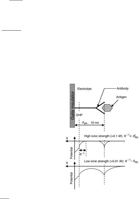
It can be seen from the equation that the Debye length is strongly dependent on the ionic strength of the solution; more precisely, the Debye length is inversely proportional to the square root of the ionic strength. Therefore, one can expect that the chance of overlapping of the double layers of the substrate-solution interface and the adsorbed proteins can be substantial only if low electrolyte concentrations are used, owing to the dimensions of the proteins (Fig. 4). In a physiological salt solution, the Debye length is limited to ca. 0.8 nm. It is obvious that only charge density changes that occur within the order of a Debye length of the ISFET surface can be detected. With the macromolecules, such as protein, the dimensions are much larger (about 10 nm) than those of the double layer of the electrolyte-insulator interface, which means that, in such a case, most of the protein charge will be at a distance greater than the Debye length from the surface. If, moreover, on top of a monolayer of antibody molecules a second layer on antigens in coupled, it is obvious that the chance of overlap of the diffuse layers of antigens with electrolyte-substrate interface will decrease even more. At high ionic strength, the additional charges of the antigen are nearly always located far outside the diffuse layer at the ISFET surface and pure electrostatic detection of these antigenic charges, therefore, is impossible. In addition, a theoretical approach is
Figure 4. Schematic representation of the potential distribution in a direct-acting IMFET. K 1 is the Debye length; dAb, dimension of macromolecule (e.g., antibody).
102 IMMUNOLOGICALLY SENSITIVE FIELD–EFFECT TRANSISTORS
given based on the Donnan equilibrium description, which provides an insight into the potential and ion distribution in the protein layer on the IMFET (32). It is shown that the Donnan potential and the internal pH shift, induced by the protein charges, compensate each other to a greater extent. If the ISFET shows Nernstian behavior, it can be concluded that a direct detection of protein charge is impossible. In order to construct an IMFET, a reference FET or ISFET with a low sensitivity would satisfy the detection of the partially compensated Donnan potential in the presence of an adsorbed protein layer. However, the application of such as IMFET is limited to samples with low ionic strength.
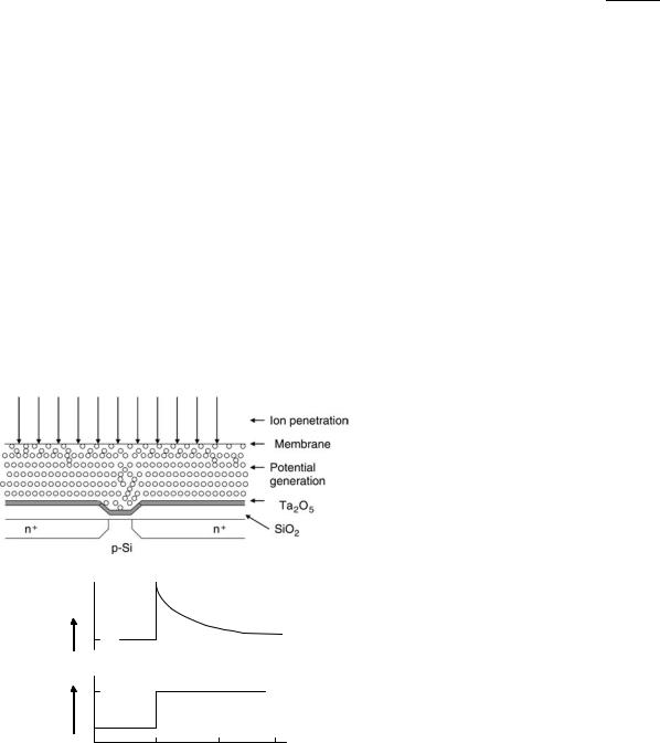
An alternative, indirect approach is proposed by Schasfoort et al. (35,36) for the detection of an immunological reaction taking place in a membrane, which covers the gate area of an ISFET (Figs. 5a and 5b). The protein layer on the gate is exposed to pulse-wise increases in electrolyte concentration. As a result, ions will diffuse into the protein layer and, because of a different mobility of anions and cations, transients in potential will occur at the protein-membrane solution interface. The ISFET, being a voltage-sensitive device, is suitable for the measurement of these transients. As the mobility of ions is a function of the charge density in the protein membrane, changes in the charge density will influence the size and direction of the transients. By exposing the ISFET to a pH gradient and a continuous series of ion concentration pulses, the isolectric point of the protein layer can be detected and, thus, changes as the result of an immunological reaction. When a membrane separates two
ø
(mV)
C2
C1
0 |
2 |
4 |
|
Time (s) |
|
Figure 5. An ion-step arrangement: an ISFET exposed to an increased electrolyte concentration. Transient potential can bemeasured, developing from transient transport of ions across the membrane, which is caused by stepwise changes in electrolyte concentration. The ISFET response f as a result of the stepwise changes in electrolyte concentration (C1–C2).
compartments with different electrolyte concentrations, a potential gradient can be measured. The different diffusion rates of anions and cations through the membrane set up a static membrane potential, which can be expressed by the Nernst–Planck equation (33):
f |
m ¼ |
RT |
:U:In |
a2 |
U |
Dþ D |
|
a1 |
|||||
|
F |
|
|
¼ Dþ þ D |
where fm ¼ the membrane potential, RT and F have their common meaning, U ¼ the ratio of the diffusion coefficients (Dþ and D ) of cations and anions, and a1 and a2 are the electrolyte activities in the respective compartments. The ion-step method is further developed by Schasfoort and Eijsma (37), and a detailed theoretical understanding of the ion-step response has been presented by Eijiki et al. (38). Recently, an impedance spectroscopy method was used tocharacterize immobilized protein layers on the gate of an ISFET and to detect an antigen-antibody recognition event (39).
Indirect-Sensing IMFET
Although the ion-step method is an indirect way of measuring antigen-antibody reaction that occurs on the gate region of an ISFET, it does not involve any reagents that enhance or amplify the signal intensity. Many approaches to transduction of the antibody-antigen combining event are indirect. They are based on the ability of an enzyme label to produce electroactive substances within a short span of time. Antibody or antigen is immobilized on the gate area of pH-FET. In the competitive binding assay, the sample antigen competes with enzyme-labeled antigen for the antibody-binding sites on the membrane. The membrane is then washed, and the probe is placed in a solution containing the substrate for the enzyme. IMFETs based on the sandwich assay are applicable for measuring large antigens that are capable of binding two different antibodies. Such sensors use an antibody that binds analyteantigen, which then binds an enzyme-labeled second antibody. After removal of the nonspecifically adsorbed label, the probe is placed into the substrate-containing solution, and the extent of the enzymatic reaction is monitored electrochemically. Gate voltage is supplied by reference electrode, such as Ag/AgCl or a Hg/Hg2Cl2 electrode, that is immersed in a sample solution. It is, however, difficult to make a small conventional electrode, which prevented the IMFET from being miniaturized as a whole. When a noble metal, such as platinum or gold, is used as a reference electrode, the potential between the metal electrode and sample solution fluctuates. The fluctuation makes stable measurement impossible. A method to cancel the fluctuation using a reference ISFET (REFET) is reported. A combination of two kinds of ISFET is used, one of which detects a specific substance whereas the other (REFET) does not detect it (Fig. 6). Thus, measuring the differential output between the two ISFETs can cancel the potential fluctuation in the sample solution and drift due ISFET (40–42).
Most of the indirect-sensing IMFET studies are carried out using urease-conjugated antibodies. Urea is used as a substrate. The immunosensor uses a reaction wherein urea is hydrolyzed by the urease-labeled second antibody. The
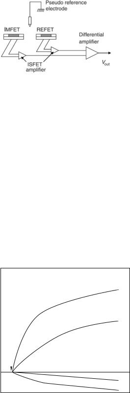
Figure 6. Differential measurement setup for an IMFET.
reaction is
H2NCONH2 þ 2H2O þ Hþ ! 2NHþ4 þ HCO3
According to the reaction, the pH value in the membrane becomes high. On the other hand, on the ISFET surface with inactive antibody membrane, the above reaction does not occur and pH remains constant. Hence, by measuring the differential output between two ISFETs, only pH changes due to urea hydrolysis are detected. In some cases, the authors used antibodies conjugated with the glucose oxidase. These sensors use oxidation of glucose by glucose oxidase. In the reaction, gluconic acid is produced and the pH value in the glucose oxidase immobilized membrane becomes low. To achieve a high sensitivity of horseradish peroxidase (HRP) detection, various substrates, either alone or in combination, are tested and the result is shown in Fig. 7.
(∆pH) |
0.8 |
|
|
|
|
|
|
|
|
|
|
|
|
1 |
|
|
|
|
|
|
|
|
|
|
|
|
|
||||
0.6 |
|
|
|
|
|
|
|
|
|
|
|
|
2 |
||
change-pH |
0.4 |
H2O2 |
|
|
|
|
|
|
|
|
|
|
|||
|
|
|
|
|
|
|
|
|
|
|
|
|
|
|
|
|
0.2 |
|
|
|
|
|
|
|
|
|
|
|
|
|
|
|
0 |
|
|
|
|
|
|
|
|
|
|
|
|
3 |
|
|
|
|
|
|
|
|
|
|
|
|
|
|
|||
|
|
|
|
|
|
|
|
|
|
|
|
|
|||
|
|
|
|
|
|
|
|
|
|
|
|
|
|
||
|
|
|
|
|
|
|
|
|
|
|
|
|
|
4 |
|
|
|
|
|
|
|
|
|
|
|
|
|
|
|
|
|
|
0 |
20 |
40 |
60 |
80 |
100 |
|||||||||
|
|
|
|
|
|
|
|
|
Time, S |
|
|
|
|
||
Figure 7. Typical ISFET responses for HRP (10 9 M) substrates
(1) Ascorbic Acid þ O-phenylenediamine (OPD); (2) OPD; (3) piodophenolþ luminol; (4) catechol.
IMMUNOLOGICALLY SENSITIVE FIELD–EFFECT TRANSISTORS |
103 |
PRACTICE
Direct-Acting IMFET
The rationale for attempting to combine the fields of immunology and electrochemistry in the design of analytical devices is that such a system should be sensitive due to the characteristics of the electrochemical detector while exhibiting the specificity inherent in the antigen-antibody reaction. The ideal situation would be to detect the binding of immunoreagents directly at an electrode, for example, by changes in surface potential, which could be truly described as an immunosensor (43,44). Much more effort has been committed to develop transducers, which rely on direct detection of antigen by the antibody immobilized on its surfaces (or vice versa). In 1975, Janata immobilized a sugar-binding protein Concanavalin A on a PVC-coated platinum electrode and studied its responses in the presence of sugar (30). The potential of the electrode with respect to an Ag/AgCl electrode changed owing to adsorption of the charged macromolecule. Although the system reported was not based on an immunochemical reaction, the finding of a potentiometric response stimulated further investigations in this field. Direct potentiometric sensing of antigen human choriogonadotropin (hCG) with an antihCG antibody sensitized titanium wire resulted in 5 mV shifts with respect to a saturated calomel electrode (45). The change in potential was explained by a simple charge transfer model.
In 1978, Schenck first proposed a concept of direct immunosensing by an ISFET (46,47). He suggested using FET with, on the gate region, a layer of antibody specific to a particular antigen. Replacement of electrolyte solution with another electrolyte solution-containing antigen should alter the charge of the protein surface layer due to the antigen-antibody reaction, thus affecting the charge concentration in the inversion layer of the transistor. The corresponding change in the drain current would then provide a measure of the antigenic protein concentration in the replacement solution. Many research groups have tried to realize the proposed concept of Schenck, but the results obtained are meager (48,49). Collins and Janata immobilized a PVC membrane containing cardiolipin antigen onto the gate of a previously encapsulated ChemFET (50). They demonstrated that the solution-membrane interface was somewhere between a polarized and a nonpolarized interface, based on the measured membrane exchange current density. The measured potential was therefore a mixed potential deriving out of the permeation of Naþ and Cl ions into and out of the membrane. The change in potential following specific binding of antibody to the membrane was due primarily to a perturbation of the mixed potential, rather than to the adsorbed charge from the antibody itself. Therefore, the device could not be considered selective for the immunoreactive species of interest. Besides, Janata reported that it is impossible to construct an IMFET without having an ideal polarized solution-insulator interface. He proclaimed all of his earlier results as artifacts (51). In spite of these practical difficulties, Gotoh et al. (52) published results obtained with an IMFET sensitive to Human serum albumin (HSA).

104 IMMUNOLOGICALLY SENSITIVE FIELD–EFFECT TRANSISTORS
Figure 8. Outline of an Ion-step flow through system.
A 2 mV shift was detected with HSA containing polyvinylbutyral membrane deposited on an ISFET after reaction with its antibody. It appears that experimental results obtained with direct detection of protein on solid-state electrode or similar devices are, so far, limited to secondorder effects. Nevertheless, a real theoretical explanation is absent. Therefore, until more experimental evidence is available, the true value of direct-acting IMFET concept remains to be established.
Schasfoort et al. (36) proposed an alternative approach to overcome the above-described difficulties of a direct detection of immunological reaction with ISFET. By stepwise changing the electrolyte concentration of the sample solution, a transient diffusion of ions through the membraneprotein layer occurs, resulting in a transient membrane potential, which can be measured by the ISFET. A flowthrough system was used to carry out the experiments as schematically drawn in Fig. 8. The pH of the electrolyte can be changed by using a gradient vessel. When the solution flows under hydrodynamic pressure out of vessel 1, the pH will change through mixing with a solution of different pH from vessel 2. By opening the value for a few seconds, the ISFET can be exposed to a higher salt concentration. The step change in join concentration was completed within 50 ms. After 2 s the valve was closed and the membrane can gain equilibrate with the buffer flowing out of vessel 1. In order to exchange the electrolyte concentration rapidly, the volume between the valve and the ISFET was kept small. ISFETs with a polystyrene-agarose membrane were incubated with 10 5 M HSA for 3 h. The ISFET response was measured as a function of the pH, and the inversion point was determined to be pI ¼ 3.72 0.05. Subsequently,
the ISFETs were incubated in different concentrations of anti-HSA antibodies solution ranging from 0.06 to 64 mM. The anti-HSA antibody was able to change the inversion point of the HSA-coated membrane from 3.70 to 5.55. The above experiments clearly demonstrated that the net charge density in a protein layer deposited on an ISFET could be determined by exposing the membrane to a stepwise change in electrolyte concentration while measuring ISFET current change. The transient membrane potential observed is a result of the different mobilities of the positive and negative ions present in the protein layer. It is also observed that characteristic inversion points and slope are a function of the protein concentration and type of protein. Also isolectric points could be detected from the membrane potentials as a function of the pH. This detection of the isoelectric point of a protein complex is the basis for the development of an IMFET. An immunological reaction results in a change of the fixed-charge density in the membrane, which can be explained by a shift of the protein isoelectric point due to the immunological reaction.
The ion-step method was originally designed to measure immunoreaction via the change in charge density, which occurs in an antibody-loaded membrane, deposited on an ISFET, upon reaction with a charged antigen. The efficacy of ion-step method for the quantification of a non-charged antigen was demonstrated using progesterone as the model analyte (53). Progesterone is an uncharged molecule, hence, it cannot be detected directly by using the ion-step method. A competitive method was devised using a charged progesterone-lysozyme conjugate. To prepare the ISFETs for ion-step measurement, a membrane support was created by depositing a 1:1 mixture of polystyrene beads and agarose on the gate. The ISFETs were then cooled to 4 8C and the solvent was slowly evaporated, leaving a porous membrane with a thickness of approximately 4 mm. The ISFET was then heated to 55 8C for 1 h to immobilize the membrane onto the gate. The ISFET was placed in the flow-through system (see Fig. 8) and a monoclonal antibody specific to progesterone was incubated on the membrane (0.5 mg/ml, 4 8C for 20 h). A competitive assay method was used to detect progesterone levels, and the detection limit was approximately 10 8 M of progesterone in the sample solution. Recently, Besselink et al. (54) described an amino bead-covered ISFET technology for the immobilization of antibodies. HSA was immobilized onto the amino bead-coated ISFET, by covalent cross-link- ing method, and the anti-HSA antibodies were quantitated using the ion-step method. The antibody concentration was detected within 15 min, with yields up to 17 mV (Fig. 9).
Indirect-Sensing IMFET
The indirect-sensing IMFET concept emerged during the early 1990s in order to overcome the difficulties met with the direct-acting IMFET devices (55). Colapicchioni et al. (56) immobilized IgG using protein A onto the gate area of an ISFET. The efficacy of the IMFET was demonstrated using Human IgG and atrazine antibodies captured using protein A. As the atrazine is a small molecule (hapten), which does not induce an immunoresponse as such, it was linked to a carrier protein. Bovine Serum Albumin (BSA)
IMMUNOLOGICALLY SENSITIVE FIELD–EFFECT TRANSISTORS |
105 |
|
0 |
(mV) |
–5 |
|
|
Potential |
–10 |
|
|
|
–15 |
|
–20 |
0.00 |
0.10 |
0.20 |
0.30 |
0.40 |
0.50 |
Time (s)
Figure 9. Ion-step responses of HSA-coated ISFET before (upper solid curve) and after incubation (for 15 min) with undiluted antiHSA (lower solid curve) and anti-BSA (dashed curve). Ion stepping was performed at pH 4.02.
was conjugated to ametryn sulfoxide, which has structural similarity with atrazine, and the ametryn-BSA conjugate was injected into rabbit to raise antibodies. A sandwich assay format was used to detect Human IgG and a competitive assay format was used to quantitate atrazine concentration. The antigen-antibody reaction was monitored by the addition antihuman IgG-GOD conjugate and ametryn-GOD, respectively. Glucose was used as the substrate and the pH variation was detected by the ISFET. The sensitivity of the assay was 0.1 mg/ml and 1 ppb for human IgG and atrazine, respectively. An ISFET-based immunosensor was demonstrated for the detection of bacterial (Clostridium thermocellum) cells. The analysis included the reaction of antibacterial antibodies with cells in suspension or after covalent immobilization of cells on porous photoactivated membranes and, subsequently, the revelation of bound antibodies by the conjugate of protein A and HRP and the quantitation of enzyme activity with ISFET. The sensitivity of the sensor was within a range of 104–107 cells per ml (57). Selvanaygam et al. (23) reported ISFET-based immunosensors for the qunatitation of b-Bungarotoxin (b-BuTx), a potent presynaptic neurotoxin from the venom of Bungarus multicinctus. A murine monoclonal antibody (mAb 15) specific to b-BuTx was immobilized on the gate area, and the antigen-antibody reaction was monitored by the addition of urease-conju- gated rabbit anti-b-BuTx antibodies. The sensor detected toxin level as low as 15.6 ng/ml. The efficacy of the sensor for the determination of b-BuTx from B. multicinctus venom was demonstrated in the mouse model.
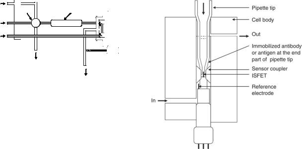
An immunological Helicobacter pylori urease analyzer (HPUA), based on solid-phase tip coated with a monoclonal antibody specific to H. pylori’s urease and ISFET, was reported by Sekiguchi et al. (58). A solid-phase tip, with an inner diameter of 0.55 mm, coated with the monoclonal antibody, was incubated for 15 min at room temperature in an endoscopically collected gastric mucus sample. The activity of urease captured on the inner surface of the solid-phase tip was measured by coupling it with an ISFET in a measuring cell containing urea solution. The pH change of urea solution after 55 s of the enzymatic
reaction inside the tip was measured by withdrawing 1.1 ml of solution toward the upstream of the tip, where the measuring ISFET was installed. One cycle of measurement was completed in 17.5 s, and the sensitivity of system was 0.2 m IU/ml. The calibration curve for the quantitation of urease is shown in Fig. 10. Clinical studies were carried out with 119 patients (75 males and 44 females with an average age of 51, ranging from 13 to 79) who underwent gatroduodenoscopy and judged necessary to evaluate the infection of H. pylori and urea breath test (UBT) was used as a gold standard. Thirty-three of the UBT positive 36 patients were positive, and 81 of UBT negative 83 patients were negative by HPUA resulting in the 92% sensitivity and 98% specificity.
An IMFET for the detection of HIV-specific antibodies based on a combination of ELISA principle and ISFET flow injection analysis setup was presented by Aberl et al. (59). The active sensing components consist of a reaction cartridge containing a carrier with the immobilized receptor layer and an ISFET sensor mounted in a flow-through cell. A flow cell was constructed using two ISFET sensors on one in a two-channel configuration (Fig. 11). The liquid
2.4
2.2
2.0
1.8
1.6
1.4
1.2
∆pH
1.0
0.8
0.6
0.4
0.2
Cut off: ∆pH =0.010
0 


0.01 |
0.1 |
1 |
10 |
100 |
1000 |
10000 |
|
Final concentration of Hp urease (mIU/ml) |
|||||
Figure 10. A standard curve for HPUA.
106 IMMUNOLOGICALLY SENSITIVE FIELD–EFFECT TRANSISTORS
Sample |
|
Valve |
Reaction cartridge |
Carrier |
ISFET 1 |
solution |
|
Reference |
ISFET 2 |
solution |
|
Roller pump |
|
|
Reference |
Waste |
electrode |
|
Waste
Figure 11. Diagrammatic representation of a flow injection system for indirect immunosensing.
headspace on top of the ISFET sensors was reduced to about 1 ml, and the dead volume of the whole sensor cell was 7ml. The detection principle was realized according to the sandwich ELISA procedure using urease as a pH shifting marker enzyme. Antigen molecules (p24 or gp120) were immobilized on cellulose nitrate membranes mounted in a special flow-by cartridge or the inner surface of Borosilicate glass capillary tubing. After blocking the unspecific binding sites, the antigen was reacted with specific serum in different dilution or nonspecific serum as a negative control. In comparison with conventional ELISA, the ISFET-FIA ELISA showed a slight lower sensitivity. The antibodies were detected in a serum diluted more than 1:12,000 in ELISA, whereas the sensitivity of the ISFET– FIA ELISA was between a 1:1000 and a 1:10,000 dilution. Glass as a support material showed highly reproducible test results when compared with cellulose nitrate membrane.
Tsuruta et al. (60) reported a fully automated ISFETbased ELISA system using a pipette tip as a solid phase and urease as a detecting enzyme. The inner wall of the end part of a pipette tip was used as a solid phase, and the urease activity of the conjugate, captured after a two-step immunoreaction, was measured by coupling the pipette tip with the ISFET in a pH measuring cell (Fig. 12). A twostep sandwich assay procedure was used for the quantitation of AFP, CEA, HBsAg, and HBsAb, and a two-step competition assay was used for HBcAb, and secondantibody configuration was used for HTLV-1 Ab. After final incubation in conjugate solution, the pipette tip was washed and it was introduced into the pH measuring cell in order to couple it with ISFET. At the same time, feeding of the substrate solution was stopped, to read the pH change for 20 s. The output (source potential) of the ISFET was read and stored in the CPU during the abovementioned 20s at 0.1 s intervals. The maximum changing rate of the source potential (DV/Dt, mV/s) was calculated from these 200 data points. The total assay time was 21 min as the sum of 5, 10, 5 and 1 min for preheating of sample, First immunoreaction, Second immunoreaction, and pH measurements, respectively. The assay speed was 60 samples/h. Assay performance, such as within run CVs, between run CVs, detection limits, and correlation with the conventional ELISA kits, were satisfactory for all of six
Figure 12. Cross-sectional view of a pH-measuring cell.
analytes. The detection limit for CEA, 0.09 mg/l was comparable to better than those reported for the most advanced chemiluminescent ELISA system (0.086 mg/l).
Polymerase chain reaction (PCR) has proven to be of great importance in clinical diagnosis (61). Usually, the PCR products have been detected by staining with ethidium bromide in qualitative methods, and fluorescent dyes in real-time quantitation. Although electrophoresis has the advantage of giving information on the molecular size of PCR products, it is not well-suited to mass screening or automation. On the other hand, real-time monitoring is well-suited for mass screening and automation but is expensive. One of the most promising methods for automatizing the detection system of PCR products is ELISA. An ISFETbased ELISA was used to quantitate PCR products (62). Double-stranded PCR products with digoxigenin and biotin at both terminals were obtained by using digoxigenin-and biotin-labeled primers. The PCR products were detected by a two-step sandwich ELISA. One ml of the solution after PCR was introduced into the end part of the solid-phase pipette tip coated with antidigoxigenin antibody. Biotin-labeled PCR products captured at the solid phase were detected with avidin-urease conjugate, and the enzyme activity was measured by the ISFET in a pH measuring cell containing urea solution. The detection limit of the system was determined using a known amount of purified PCR product labeled with digoxigenin and biotin, and it was found that 10 amol of the labeled DNA in 1 ml sample. The assay was used to detect HTLV-1 provirus gene integrated in the genome of human MT-Cell, and it was found that 100 pg of the genomic DNA was specifically detectable after 35 cycles of PCR. The apparent dynamic range for detection of MT-1 DNA was from 100 pg to 100 ng.
One of the most important targets in molecular biology is the quantitation of mRNA related to special disease by RT-PCR. The accuracy of quantitative RT-PCR has been remarkably improved by the introduction of competitive
IMMUNOLOGICALLY SENSITIVE FIELD–EFFECT TRANSISTORS |
107 |
RT-PCR, in which a synthetic RNA is used as an internal standard (63). Tsuruta et al. (64) developed a ISFETELISA method for the qantitatiion of mRNA in clinical samples. In this method, a fixed amount of a synthetic RNA, pRSET RNA, was added as internal standard to the solution of target RNA (IL-1b) after reverse transcription, PCR was carried out using digoxigenin-labeled sense primer and biotin-labeled antisense primer for IL-1b, and FITC-labeled sense primer and a biotin-labeled antisense primer for pRSET. The double-stranded PCR products of IL-1b and pRSET were captured by two solid-phase pipette tips, one coated with antidigoxigenin antibody and another with anti-FITC antibody, respectively, and sandwiched by an avidin-urease conjugate, whose activity was measured with ISFET. The ratio of the signal intensity for IL-1b to that for pRSET was used to quantitate the concentration of IL-1b. A calibration curve was obtained using a known amount of AW109 RNA as an external standard in place of IL-1b m RNA. It was found that 102–106 copies of IL-1b mRNA were measurable by the present method. Expression levels of IL-1b mRNA in clinical samples, such as monocytes of peripheral blood or synovial cells from patients with RA or OA, were determined.
Practical Limitations
In this section, we shall address some practical problems that have been limiting factors in the commercial application of IMFETs. The widespread use of IMFETs for applications ranging from medical diagnosis to industrial process control or environmental monitoring has not actually happened. The underlying reasons for this situation fall into two main categories, those that are inherent to the transistor, such as material, encapsulation, and reference electrode, and those problems common to its application as an immunosensor function, such as, antibody immobilization, stability, and durability. The pH sensing properties and drift behavior of the ISFET is the main limiting factor in the commercial breakthrough of ISFET. After the invention of the ISFET, initially the only gate material used was SiO2. Although SiO2 showed pH, sensitivity of 20 to 40 mV/ pH, the thermally grown gate oxide loses its isolation property within a few hours of immersion in a solution. In order to isolate this gate oxide from the solution, another isolating layer, such as Si3N4, Al2O3, or Ta2O5, has to be placed on top of this gate oxide. A layer of Si3N4 on top of SiO2 showed 45–50 mV/pH, and other layers, such as Al203 and Ta2O5, showed even higher pH sensitivity, 53–57 mV/ pH and 55–59 mV/pH, respectively (65). Drift rate for Si3N4 is reported as 1 mV/h and for Al2O3 and Ta2O5 0.1–0.2 mV/ h after 1000 min of operation at pH 7.0. In most of the work on IMFETs published so far, these three gate materials, Si3N4, Al2O3, and Ta2O5, have been used. IMFETs are also sensitive to light and temperature (66).
The pH-sensitive ISFETs can be fabricated by means of standard MOS technology, except for the metallization step. However, after dicing the wafers into single chips, the substrate becomes exposed at the edges of the senor. Encapsulation and packaging are two final processing steps that determine reliability and durability (lifetime) of the IMFETs. In order to achieve high quality sensors, all
electrical components have to be isolated from their surroundings. Several reports exist on the encapsulation and packaging of ISFET devices for pH application (21). The simplest method of isolating these sides is encapsulation with epoxy-type resins. The most important ISFET characteristics, such as stability, accuracy, and durability, also pertain to the reference electrode. One of the major hurdles in IMFETs is the lack of a solid-state reference electrode. The small IMFETs have to be combined with a conventional KCl-solution-filled reference electrode. In order to achieve miniaturized IMFET, it is important to miniaturize the reference electrode. In general, two approaches have been followed: reference FETs (REFETs), which are used in an ISFET/REFET/quasi-reference electrode setup, and miniaturized conventional reference electrodes. In the first approach, attempts have been made to cover the ISFET surface with a pH-insensitive layer or to render the surface pH insensitive by chemical modification. In the second approach, the structure of a conventional electrode (mostly Ag/AgCl type) is miniaturized partially or completely on a silicon wafer. Its potential is a function of concentration of chloride ions. They are supplied either from an internal electrolyte reservoir formed by an anisotropic etching in the silicon wafer or by adding chloride ions into the test solution.
Some of the technological factors such as pH sensitivity and drift can now be overcome with the existing technology. A hurdle peculiar to direct-acting IMFET is the need to provide a thin but fully insulating layer (membrane) between the antigen or antibody coating and the semiconductor surface. Such a membrane must be thin enough to allow a small charge redistribution occurring as a result of analyte (antigen-antibody) binding to exert a detectable change in electrical field. Conversely, it must also provide adequate insulation to prevent dissipation of the field by leakage of ions. Even assuming that the ideal insulating membrane can be developed, a further hurdle may need to be overcome. Surface charges and hydrogen binding sites of proteins cause a counter-ion shell (double-layer) and structured water shells to surround the molecules; these regions of structured charge will inevitably contribute to the electrical field affecting the FET gate. Pending these breakthroughs, the development of direct-acting IMFETs appears to be stagnant.
The immobilization methods used for immunosensors include a variety of adsorption, entrapment, cross-linking, and covalent methods. In general, a covalent immobilization method consisting of silanization step and subsequent coupling procedure via glutaraldehyde has been used to immobilize antibodies onto the gate region (67,68). However, no methodical investigation about antibody stability, storage, and lifetime exists. Reproducible regeneration of the sensing area is one of the major problems met with IMFETs that have been used for continual monitoring or repeat usage. The need for renewal of the sensing surface derives from the high affinity constants derived from the strong antigen-antibody reaction. Two different strategies have been used to achieve the renewal of the sensing surface, breakage of the antigen-antibody bond and reusing the immunologic reagent immobilized on the solid phase. A second alternative is the elimination of antigen-antibody
108 IMMUNOLOGICALLY SENSITIVE FIELD–EFFECT TRANSISTORS
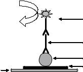
complex from the solid support and immobilization of fresh immunologic material. Dissociation of antigen from antibody is usually carried out in low pH and high ionic strength solutions. Protein A was chemically immobilized onto the gate surface by using a polysiloxane layer of [3-(2-ami- noethyl)aminopropyl]trimethoxysilane (APTES) and cross-linking agent such as glutaraldehyde. Reversibility of the linkage between Protein A and antibodies in order to restore the device for the next measurement was studied by breaking the antibody-antigen complex formed on Protein A using a variety of reagents. Glycine buffer pH 2 and 3 and MgCl2 3.5 M were found to be more effective when compared with other tested reagents due to high ionic strength (55). Selvanayagam et al. (23) studied the reusability of an ISFET sensor by removing the antibody membrane from the gate area. The regenerated devices tested were reported to function normally five times, although a considerable amount of time was required for the regeneration process. Recently, IMFET using magnetic particle and integrated to flow injection system has been described to overcome the problem of regeneration (69,70). The immunological material was immobilized on the surface of magnetic particles and were transported by a flow system, and were retained on the gate area of the ISFET by a magnetic field produced by a magnet (Fig. 13). The regeneration of immunologic materials was achieved by releasing the magnetic field, thus freeing those particles that were washed by the flow system, and new magnetic particles were injected and retained on the surface of transducer by reacting the magnetic field. A fresh and reproducible surface was thus produced, ready for the next analytical cycle.
The main barrier to the successful introduction of IMFETs for clinical testing is undoubtedly the high performance and automation level of the machines that already exist in centralized laboratories. They have been developed specifically for use with either immunoassay or clinical chemistry. Immunoassay performance is continually being optimized and assay times have been reduced over the past few years. Depending on the parameter, the assay time can be as low as 6 min and the majority of the larger machines could carry out between 100 to 200 testes per hour. IMFETs must be compared with these methods with respect to assay time, sensitivity, and cost. The need for in-built calibration has been frequently encountered in sophisticated quantitative IMFETs. Although feasible and acceptable in laboratory-based instrumentation, it remains
H2 N-CO-NH2
H 2O |
Ureaseconjugate |
2nd antibody
CO2 + 2 NH3
Rabbit IgG
Magnetic particle
ISFET
Magnet
Figure 13. Schematic representation of the magnetoIMFET.
a major problem in small disposable IMFET devices. To facilitate the increased use of IMFETs, one should look for real tests and standards that prototypes can meet, based on current diagnostic needs and perceived future development. The progress of IMFET beyond the experimental laboratory level is mainly dependent on how skillfully its development and marketing are combined with parameter selection.
FUTURE DIRECTIONS
A key consideration in antibody immobilization to the gate area is to maintain, reproducibly, the highest possible binding activity after immobilization while conserving the amount of antibody used. However, many aspects, both fundamental and more applied, require in-depth study before IMFETs can become successful commercial device, including improved control of biomolecule immobilization and novel immobilization strategies; enhancement of biomolecule stability and retention of activity in vitro; and the ability to reproduce the high signal-to-noise ratios obtained in simple test solutions in ‘‘real’’ samples such as blood or water. The IMFETs tends to respond nonspecifically to any molecule bound to the surface; hence, it affects the measurement parameter to some extent. The specificity of analyte detection, therefore, relies entirely on achieving high ratios of specific to nonspecific binding, which, in the context of low concentrations of analyte in blood, can represent a formidable problem. Reduction of nonspecific binding is another area that will continue to be of major importance. The ability to immobilize ordered antibodies will maximize antigen binding to a given surface while reducing the availability of nonbinding site sections of the immobilized antibody, or uncovered surface areas, which can promote nonspecific interaction with other components in the sample. The potential advantages of using Fab fragments rather than more complex intact antibodies (such as IgG) could be explored.
IMFETs, similar to immunoassays, involve multistep procedures, including washing steps, incubation periods, and quite complex signal generation protocols. It is likely that research efforts into a novel signal amplification system, without the normally associated complications of multi-reagents or multistep protocol will be of increasing importance. The irreversibility of antigen-antibody interaction presents a major challenge in designing IMFETs for continual monitoring or repeated usage. Treatment of an antibody-antigen complex with a mildly denaturing medium for a short time interval has shown some promise in regenerating sensor surfaces. Development of enhanced denaturation conditions, which optimize dissociation of antigen while minimizing irreversible loss of antibody structural integrity, may be possible in the near future. The use of catalytic antibodies in immunosensors has been proposed. The ability of catalytic antibodies to catalyze the hydrolysis of phenyl acetate with the formation of acetic acid allows integration of pHsensitive microelectrodes to give a potentiometric immunosensing system (71). The advantage of catalytic antibodies over normal antibodies is that reversibility of
IMMUNOLOGICALLY SENSITIVE FIELD–EFFECT TRANSISTORS |
109 |
response is readily achieved, because bound antigen reacts to form a product with a low affinity for the antibody, resulting in dissociation. As the binding event is followed immediately by a catalytic reaction and release of the reaction products, the molecular recognition site is regenerated with each molecular reaction; as a consequence, catalytic antibodies can be used to create reversible IMFETs for continuous monitoring of analyte concentrations. Improvements in sensitivity and crossreactivity are likely to be achieved as a result of the increasing interest in this field of research.
CONCLUSION
Although the ISFET concept has existed for over 30 years, its practical applications such as the IMFETs are still emerging very slowly. The relatively slow rate of progress of IMFET technology from inception to fully functional commercial devices for these applications is a reflection of technology-related and market factors. In general, two approaches have been followed in the past to realize IMFETs. In the first approach, antigen-antibody reaction on an immonbilized membrane was monitored without any addition of labels. The second approach takes the advantage of an enzyme label to indirectly monitoring the antigen-antibody reaction using pH-sensitive FET. The development of IMFETs that directly detect antigen-antibody reaction is extremely challenging; only a few examples exist, the majority of which are without valid theoretical explanation. Although it shows enormous promise in the early stages of development, an effective, reliable, and analyte-selective direct-acting IMFET sensor is yet to be constructed. The ion-step method represents a novel measurement concept for potentiometric detection and quantification of an adsorbed antigen or antibody molecule in which modified ISFETs are used. Many approaches to transduction of the antibody-antigen combining event are indirect, necessarily involving the use of reagents admixed with analyte, and therefore cannot be seen as routes to development of ‘‘True’’ IMFETs. Nevertheless, such reagent-dependent, indirect-sensing IMFETs may offer real commercial advantages over the current generation direct-acting IMFET readout technologies. The clinical diagnostic field offers real opportunities for the exploitation of IMFET, but because it is a highly competitive and well-established market, those who wish to introduce new products must carefully target their market niche. IMFETs will have to compete with such technology on the basis of factors such as cost, ease of use, sensitivity, operational stability, robustness, and shelf-life.
BIBLIOGRAPHY
1.Catty D. editor, Antibodies Volume 1. A Practical Approach. Washington, DC: IRL; 1988.
2.Mayforth RD. Designing Antibodies. New York: Academic Press; 1993.
3.Johnstone AP, Turner MW. Immunochemistry 1. A Practical Approach. New York: IRL; 1997.
4.Bluestein BI, Walczak IM, Chen SY. Fiber optic evanescent wave immunosensors for medical diagnostics. Trends Biotechnol 1990;8:161–168.
5.Gosling JP, A decade of development in immunoassay methodology. Clin Chem 1990;36:1408–1427.
6.Kemeny DM, A Practical Guide to ELISA. New York: Pergamon Press; 1991.
7.Turner APF, Karube I, Wilson GS. editors. Biosensors: Fundamentals and Applications. New York: Oxford University Press; 1987.
8.Buerk DG, Biosensors: Theory and Applications. Lancester, PA: Technomic; 1993.
9.Eggins BR. Biosensors: An Introduction. New York: Wiley; 1996.
10.Aizawa M. Principles and applications of electrochemical and optical biosensors. Anal Chim Acta 1991;250:249–256.
11.North JR. Immunosensors: Antibody-based biosensors. Trends Biotechnol 1985;3:180–186.
12.Aizawa M. Immunosensors for clinical analysis. Adv Clin Chem 1994;31:247–275.
13.Morgan LC, Newman DJ, Price CP. Immunosensors: Technology and opportunities in laboratory medicine. Clin Chem 1996;42:193–209.
14.Ghindilis AL, Atanasov P, Wilkins M, Wilkins E. Immunosensors: Electrochemical sensing and other engineering approaches. Biosens Bioelecton 1998;13:113–131.
15.Bergveld P. Future applications of ISFETs. Sens Actuators B 1991;4:125–133.
16.Kuriyama T, Kimura J. An ISFET biosensor. In: Wise DL, editor, Applied Biosensors. Boston, MA: Butterworth; 1989.
17.Kimura J, Kuriyama T. FET biosensors. J Biotechnol 1990;15:239–254.
18.Van der Schoot BH, Bergveld P. ISFET based enzyme sensors. Biosensors 1987/88;3:161–186.
19.Yuquing M, Jianguo G, Jianrong C. Ion-sensitive field effect transducer-based biosensors. Biotechnol Advances 2003; 21:527–534.
20.Janata J, Moss SD. Chemically sensitive field-effect transistors. Biomed Eng 1976;11:241–245.
21.Bergveld P, Sibbald A. Comprehensive Analytical Chemistry, XXIII: Analytical and Biomedical Applications of Ion-Selective Field-Effect Transistors. New York: Elsevier; 1988.
22.Bergveld P. Thirty years of ISFETOLOGY. What happened in the past 30 years and what may happen in the next 30 years. Sens Actuators B 2003;88:1–20.
23.Selvanayagam ZE, Neuzil P, Gopalakrishnakone P, Sridhar U, Singh M, Ho LC. An ISFET-based immunosensor for the detection of b-Bungaraotoxin. Biosens Bioelectron 2003; 10:405–414.
24.Janata J, Huber RJ. Chemically sensitive field effect transistors. In: Freiser H, editor. Ion-Sensitive Electrodes in Analytical Chemistry, vol. II, New York: Plenum Press; 1980.
25.Janata J, Blackburn GF. Immunochemical potentiometric sensors. Ann N Y Acad Sci 1984;428:286–292.
26.Blackburn GF. Chemically sensitive Field effect transistors. In: Turner APF, Karube I, Wilson S. editors. Biosensors: Fundamentals and Applications. Oxford: Oxford Science Publications; 1987.
27.Bockris JOM, Reddy AKN. Modern Electrochemistry, vol. 2. New York: Plenum Press; 1970.
28.Eisen HN. Immunology. An Introduction to Molecular and Cellular Principles of the Immune Response. New York: Harper and Row; 1974.
29.Bergveld P. A critical evaluation of direct electrical protein detection methods. Biosens Bioelecton 1991;6:55–72.
30.Janata J. An immunoelectrode. J Am Chem Soc 1975;97:2914– 2916.
110 IMMUNOLOGICALLY SENSITIVE FIELD–EFFECT TRANSISTORS
31.Janata J, Janata J. Novel protein-immobilizing hydrophobic polymeric membrane, process for producing same and apparatus employing same. U.S. Patent 3,966,580, 1976.
32.Schasfoort RBM, Bergveld P, Kooyman RPH, Greve J. Possibilities and limitations of direct detection of protein changes by means of immunological field-effect transistor. Anal Chim Acta 1990;238:323–329.
33.Moore WJ. Physical Chemistry. London: Longman; 1976.
34.Davies JT, Rideal EK. Interfacial Phenomena. London: Academic Press; 1963.
35.Schasfoort RBM, Bergveld P, Bomer J, Kooyman RPH, Greve J. Modulation of the ISFET response by an immunological reaction. Sens Actuators 1989;17:531–535.
36.Schasfoort RBM, Kooyman RPH, Bergveld P, Greve J. A new approach to ImmunoFET operation. Biosens Bioelecton 1990; 5:103–124.
37.Schasfoort RBM, Eijsma B. The ions-step method applied to disposable membranes for the development of ion-responding immunosensors. Sens Actuators 1992;6:308–311.
38.Eijkel JCT, Olthuis W, Bergveld P. An ISFET-based dipstick device for protein detection using the ion-step method. Biosens Bioelectron 1997;12:991–1001.
39.Kharitonov AB, Wasserman J, Katz E, Willner I. The use of impedance spectroscopy for the characterization of proteinmodified ISFET devices: Application of the method for the analysis of biorecognition processes. J Phys Chem 2001; B- 105:4205–4213.
40.Sergeyeva TA, Soldatkin AP, Rachkov AE, Tereschenko MI, Piletsky SA, Elskaya AV. b-Lactamase label-based potentiometric biosensor for a-2 interferon detection. Anal Chim Acta 1999;390:73–81.
41.Yacoub-George E, Wolf H, Koch S, Woias P. A miniaturized ISFET-ELISA system with a pre-treated fused silica capillary as reaction cartridge. Sens Actuators B 1996;34:429–434.
42.Starodub NF, Dzantiev BB, Starodub VN, Zherdev AV. Immunosensor for the determination of the herbicide simazine based on an ion-selective field-effect transistor. Anal Chim Acta 2000;424:37–43.
43.Wang J. Electroanalytical Techniques in Clinical Chemistry and Laboratory Medicine, New York: VCH; 1988.
44.Luppa PB, Sokoll LJ, Chan DW. Immunosensors — principles and applications to clinical chemistry. Clin Chim Acta 2001;314:1–26.
45.Yamamoto N, Nagasawa Y, Sawai M, Sudo T, Tsubomura H. Potentiometric investigations of antigen-antibody and enzyme-enzyme inhibitor reactions using chemically modified metal electrodes. J Immunol Methods 1978;22:309–317.
46.Schenck JF. Technical difficulties remaining to the application of ISFET devices. In: Cheung PW, editor. Theory, Design and Biomedical Applications of Solid State Chemical Sensors. New York: CRC; 1978.
47.Schenck JF. Field effect transistor for detection of biological reactions. U.S. Patent 4,238, 757, 1980.
48.Schoning MJ, Poghossiana A. Recent advances in biologically sensitive field-effect transistors (BioFETs). Analyst 2002; 127:1137–1151.
49.Janata J, Thirty years of CHEMFETs — a personal view. Electroanalysis 2004;16:1831–1835.
50.Collins S, Janata J. A critical evaluation of the mechanism of potential response of antigen polymer membrane to the corresponding antiserum. Anal Chim Acta 1982;136:93–99.
51.Janata J. Proceedings of the 2nd International Meeting on Chemical Sensors; 1986:25–31.
52.Gotoh M, Tamiya E, Karube I. Micro-FET biosensors using polyvinylbutyral membrane. J Membrane Sci 1989;41:291– 303.
53.Schasfoort RBM, Keldermans CEJM, Kooyman RPH, Bergveld P, Greve J, Competitive immunological detection of progesterone by means of the ion-step induced response of an immunoFET. Sens Actuators 1990;BI:368–372.
54.Besselink GAJ, Schasfoort RBM, Bergveld P. Modification of ISFETs with a monolayer of latex beads for specific detection of proteins. Biosens Bioelecton 2003;18:1109–1114.
55.Toshihide K. Electrochemical sensors in immunological measurement. E.U. Patent 0,328,380, 1998.
56.Colapicchioni C, Barbaro A, Porcelli F, Giannini I. Immunoenzymatic assay using CHEMFET devices. Sens Actuators B 1991;6:186–191.
57.Akimeno VK, Khomutov SM, Obraztsova AY, Vishnivetskii SA, Chuvilskaya NA, Laurinavichus KS, Reshetilov AN. A rapid method for detection of Clostridium thermocellum by field-effect transistor immunodetection. J Microbiol Methods 1996;24:203–209.
58.Sekiguchi T, Nakamura M, Kato M, Nishikawa K, Hokari K, Sugiyama T, Asaka M. Immunological Helicobacter pylori urease analyzer based on ion-sensitive field effect transistor. Sens Actuators 2000;B67:265–269.
59.Aberl F, Modrow S, Wolf H, Koch S, Woias P. An ISFET-based FIA system for immunosensing. Sens Actuators 1992;B6:186– 191.
60.Tsuruta H, Yamada H, Motoyashiki Y, Oka K, Okada C, Nakamura M. An automated ELISA system using a pipette tip as a solid phase and a pH-sensitive field effect transistor as a detector. J Immunol Methods 1995;183:221–229.
61.Saiki R, Scharf S, Faloona F, Mullis K, Horn G, Erlich H, Arnheim N. Enzymatic amplification beta-globulin genomic sequences and restriction analysis for diagnosis of sickle cell anemia. Science 1985;230:1350–1354.
62.Tsuruta H, Matsui S, Hatanaka T, Namba T, Miyamoto K, Nakamura M. Detection of the products of polymerase chain reaction by an ELISA system based on an ion-sensitive field effect transistor. J Immunol Methods 1994;176:45–52.
63.Wang AM, Doyle MV, Mark DF. Quantitation of mRNA by the polymerase chain reaction. Proc Natl Acd Sci USA 1989; 86:9717–9721.
64.Tsuruta H, Matsui S, Oka K, Namba T, Shinngu M, Nakamura M. Quantitation of IL-1-beta mRNA by a method of RTPCR and an ELISA based on ion-sensitive field effect transistor. J Immunol Methods 1995;180:259–264.
65.Gopel W, Hesse J, Zemel JN editorss. Sensors: A Comprehensive Survey, Chemical and Biochemical Sensors, Part I. Verlagsgesellschaft Mbh: VCH; 1991.
66.Neuzil P. ISFET integrated sensor technology. Sens Actuators 1995;B24-25:232–235.
67.Filippo P, Antonio NC. Sensor with antigen chemically bonded to a semiconductor device. E.U. Patent 0,395,137, 1990.
68.Starodub NF, Samodumova IM, Starodub VN. Usage of organosilanes for integration of enzymes and immunocomponents with electrochemical and optical transducers. Sens Actuators 1995;B24-25:173–176.
69.Santandreu M, Sole S, Fabregas E, Alegret S. Development of electrochemical immunosensing systems with renewable surfaces. Biosens Bioelectron 1998;13:7–17.
70.Sole S, Alegret S, Cespedes F, Fabregas E. Flow injection immunoanalysis based on a magnetoimmunosensor system. Anal Chem 1998;70:1462–1467.
71.Blackburn GF, Talley DB, Booth PM, Durfor CN, Martin MT, Napper AD, Rees AR. Potentiometric biosensor employing catalytic antibodies as the molecular recognition element. Anal Chem 1990;62:2211–2216.
See also ION-SENSITIVE FIELD EFFECT TRANSISTORS.