

- •VOLUME 4
- •CONTRIBUTOR LIST
- •PREFACE
- •LIST OF ARTICLES
- •ABBREVIATIONS AND ACRONYMS
- •CONVERSION FACTORS AND UNIT SYMBOLS
- •HYDROCEPHALUS, TOOLS FOR DIAGNOSIS AND TREATMENT OF
- •HYPERALIMENTATION.
- •HYPERBARIC MEDICINE
- •HYPERBARIC OXYGENATION
- •HYPERTENSION.
- •HYPERTHERMIA, INTERSTITIAL
- •HYPERTHERMIA, SYSTEMIC
- •HYPERTHERMIA, ULTRASONIC
- •HYPOTHERMIA.
- •IABP.
- •IMAGE INTENSIFIERS AND FLUOROSCOPY
- •IMAGING, CELLULAR.
- •IMAGING DEVICES
- •IMMUNOLOGICALLY SENSITIVE FIELD–EFFECT TRANSISTORS
- •IMMUNOTHERAPY
- •IMPEDANCE PLETHYSMOGRAPHY
- •IMPEDANCE SPECTROSCOPY
- •IMPLANT, COCHLEAR.
- •INCUBATORS, INFANTS
- •INFANT INCUBATORS.
- •INFUSION PUMPS.
- •INTEGRATED CIRCUIT TEMPERATURE SENSOR
- •INTERFERONS.
- •INTERSTITIAL HYPERTHERMIA.
- •INTRAAORTIC BALLOON PUMP
- •INTRACRANIAL PRESSURE MONITORING.
- •INTRAOCULAR LENSES.
- •INTRAOPERATIVE RADIOTHERAPY.
- •INTRAUTERINE DEVICES (IUDS).
- •INTRAUTERINE SURGICAL TECHNIQUES
- •ION-EXCHANGE CHROMATOGRAPHY.
- •IONIZING RADIATION, BIOLOGICAL EFFECTS OF
- •ION-PAIR CHROMATOGRAPHY.
- •ION–SENSITIVE FIELD-EFFECT TRANSISTORS
- •ISFET.
- •JOINTS, BIOMECHANICS OF
- •JOINT REPLACEMENT.
- •LAPARASCOPIC SURGERY.
- •LARYNGEAL PROSTHETIC DEVICES
- •LASER SURGERY.
- •LASERS, IN MEDICINE.
- •LENSES, CONTACT.
- •LENSES, INTRAOCULAR
- •LIFE SUPPORT.
- •LIGAMENT AND TENDON, PROPERTIES OF
- •LINEAR VARIABLE DIFFERENTIAL TRANSFORMERS
- •LITERATURE, MEDICAL PHYSICS.
- •LITHOTRIPSY
- •LIVER TRANSPLANTATION
- •LONG BONE FRACTURE.
- •LUNG MECHANICS.
- •LUNG PHYSIOLOGY.
- •LUNG SOUNDS
- •LVDT.
- •MAGNETIC RESONANCE IMAGING
- •MAGNETOCARDIOGRAPHY.
- •MANOMETRY, ANORECTAL.
- •MANOMETRY, ESOPHAGEAL.
- •MAMMOGRAPHY
- •MATERIALS, BIOCOMPATIBILITY OF.
- •MATERIALS, PHANTOM, IN RADIOLOGY.
- •MATERIALS, POLYMERIC.
- •MATERIALS, POROUS.
- •MEDICAL EDUCATION, COMPUTERS IN
- •MEDICAL ENGINEERING SOCIETIES AND ORGANIZATIONS
- •MEDICAL GAS ANALYZERS
- •MEDICAL PHOTOGRAPHY.
- •MEDICAL PHYSICS LITERATURE
- •MEDICAL RECORDS, COMPUTERS IN
- •MICROARRAYS
- •MICROBIAL DETECTION SYSTEMS
- •MICROBIOREACTORS
- •MICRODIALYSIS SAMPLING
- •MICROFLUIDICS
- •MICROPOWER FOR MEDICAL APPLICATIONS
- •MICROSCOPY AND SPECTROSCOPY, NEAR-FIELD
- •MICROSCOPY, CONFOCAL
- •MICROSCOPY, ELECTRON
- •MICROSCOPY, FLUORESCENCE
- •MICROSCOPY, SCANNING FORCE
- •MICROSCOPY, SCANNING TUNNELING
- •MICROSURGERY
- •MINIMALLY INVASIVE SURGICAL TECHNOLOGY
- •MOBILITY AIDS
- •MODELS, KINETIC.
- •MONITORING IN ANESTHESIA
- •MONITORING, AMBULATORY.
- •MONITORING, FETAL.
- •MONITORING, HEMODYNAMIC
- •MONITORING, INTRACRANIAL PRESSURE
- •MONITORING, NEONATAL.
- •MONITORING, UMBILICAL ARTERY AND VEIN
- •MONOCLONAL ANTIBODIES
- •MOSFET.
- •MUSCLE ELECTRICAL ACTIVITY.
- •MUSCLE TESTING, REHABILITATION AND.
- •MUSCULOSKELETAL DISABILITIES.
322 MEDICAL GAS ANALYZERS
MEDICAL GAS ANALYZERS
TADEUSZ M. DRZEWIECKI
JERRY M. CALKINS
Defense Research Technologies,
Inc.
Rockville, Maryland
INTRODUCTION
Medical gas monitoring has been so successful in improving patient safety and reducing patient risk that it has become standard medical practice today in every part of medical practice from hospital to home. The argument for providing additional patient safety will continue to be a powerful incentive to improve and enhance the methods and techniques to provide increased knowledge of the monitoring of respiratory and anesthetic gases. Research on gas markers to aid in diagnosis is an equally important application, and with the capability to measure gases at parts per billion or even trillion, heretofore unobserved gases can point to early diagnosis of such nearly always fatal neonatal diseases as necrotizing enterocolitis and other difficult-to-diagnose states.
Medical gas analyzers are used to sample and measure gases of medical importance, such as anesthesia and respiratory monitoring, and detection of trace gases for diagnostic purposes. This article predominantly discusses these two cases. The estimation of arterial blood gases is considered only in terms of measurement of respired gases. Two basic categories of sensor/analyzers exist: continuous and batch. Gas analyzers are further broken down by their sensing mechanisms into two fundamental modes of operation, specific and analytic.
Continuous devices are used where real-time information is needed. Batch systems operate on a bolus of gas, usually when real-time information is not needed. Many applications may have to live with the offline, longer duration of a batch test because nothing else is available.
Specific-type sensors rely on particular physical phenomena that are activated in the presence of a particular gas. Electrochemical devices, for example, are representative of a specific sensor wherein a voltage is developed by a chemical reaction between the sensor material and the gas being analyzed in some identified or known proportion to the amount of gas present. The same is true of fuel cells and other galvanic devices where an electric potential is developed in the presence of a difference in partial pressures across a conducting medium.
Specificity is a major issue and is of particular importance to the medical community. At this point in time, no truly specific sensors exist. All sensors exhibit some form of cross-sensitivity to a variety of gases, some in the same family, some with similar physical properties, and some for extraneous reasons not always obvious to the user. Nitrous oxide (N2O) and carbon dioxide (CO2) have practically the same molecular weight, 44.0128 versus 44.0098. Consequently, they have near-identical physical characteristics such as specific heat and viscosity. Interestingly, they also have almost exactly the same absorption wavelengths, although not necessarily because the atomic weights are
the same but rather because the orbital electron transition energetics are similar. Thus, it is difficult to distinguish the two with most conventional techniques, and a carbon dioxide sensor that is based on absorption at 4.3 mm will be affected by the presence of nitrous oxide with its peak absorption at 4.5 mm. Unless a very narrow wavelength light source is used, such as a laser, the nitrous oxide will absorb some of the energy and make it appear that more carbon dioxide is present than there really is.
Analytic devices imply an ability to assay a gas or gas mixture and tell the user not only how much of a particular gas is present, but also which gases or elements are present and in what relative quantities, of which optical spectroscopy is a good example where a large number of absorption lines exist for different gases, so one can scan the entire spectrum from ultraviolet (UV) to far infrared (IR) and compare absorption lines to see what is present. This example is interesting because IR spectroscopy can also be the basis for a specific sensor when only a single or a particular wavelength of light is monitored looking only for a gas at that absorption line. Gas chromatography (GC) is also a batch process where a bolus of gas to be assayed is separated into its constituent parts in time by a molecular sieve and the binary pairs (the carrier and the separated gas) are detected and quantized upon exiting the GC column.
Perhaps the most common use of and need for continuous gas analysis or sensing is in real-time respiratory applications where inspired and expired (end-tidal) concentrations of respiratory gases are measured to validate that the appropriate standards of care are being applied and that proper ventilation and oxygenation of a patient is being achieved. An example would be monitoring of a ventilated patient in the ICU or recovery room. In addition, the monitoring of anesthetic gases during and immediately following anesthetic administration in the operating room is a critical application that can mean the difference between life and death. Too much can lead to brain damage or death, and too little can result in unnecessary pain and memory recall. And, of course, the detection and warning of the presence of toxic gases such as carbon monoxide released from desiccated soda lime CO2 scrubbers due to interactions between the anesthetic agents and various scrubbers, or the production of the highly toxic Compound A, is critical to patient safety.
Continuous medical gas monitoring provides the clinician with information about the patient’s physiologic status, estimates of arterial blood gases, verifies that the appropriate concentrations of delivered gases are administered, and warns of equipment failure or abnormalities in the gas delivery system. Monitors display inspired and expired gas concentrations and sound alarms to alert clinical personnel when the concentration of oxygen (O2), carbon dioxide (CO2), nitrous oxide (N2O), or volatile anesthetic agent falls outside the desired set limits.
Medical gas analysis has been driven by a need for safety and patient risk reduction through respiratory gas analysis and identification and quantification of volatile anesthetic vapors. Perhaps one of the earliest anesthetic agent sensors was the Drager Narkotest, which comprised a polymer rubber membrane that contracted and moved a needle as it absorbed agent. It did not require
an electrical power supply and its slow response was not any slower than the rate of change of gas composition. Much has transpired since those early days.
Currently, numerous methods and techniques of gas monitoring are in place, and new techniques and paradigms are constantly being developed to meet a new need or to serve the community with better performance or lower cost. In this review, many of the intrinsic advantages and disadvantages of these methods and techniques are discussed. A brief comparison, which includes stand-alone and multioperating room gas monitors that can determine concentrations of anesthetic and respiratory gases in the patient breathing circuit during anesthesia, is also presented.
Much of the research and development of these monitors have followed the long use of similar detector principles from analytical chemistry. As a result of the fast pace of sensor development, to a great extent driven by the need for hazardous gas sensors in the face of terrorist threats and being spearheaded by agencies such as the Defense Department’s Defense Advanced Research Projects Agency (DARPA), an attempt is made to cover the most common systems and provide insights into the future based on solid technological developments.
The current development of gas analyzers is described in the extensive anesthesia and biomedical engineering literature. Complete and specific historical information about the principles and applications of these devices is well reviewed in several texts [e.g., Ref. (1)], manufacturers’ and trade publications [(2) (ECRI)], and an extensive open literature describing equipment and operating principles, methods, and techniques that is available on the Internet. Societies and professional associations also exist that deal with just one method of gas analysis that can provide in-depth information about their particular interests. The Chromatographic Society is one such organization. It is the purpose of this article to concisely summarize such a large selection of information sources to a manageable few, but with enough references and pointers to allow even the casual reader to obtain whatever relevant information at whatever level is required.
CURRENT GAS MONITOR METHODS AND TECHNIQUES
As a result of the chemically diverse substances to be measured, medical gas analyzers commonly combine more than one analytical method. Methods of interest to the medical practitioner, clinician, researcher, or operator include, in alphabetical order:
Colorimetry
Electrochemistry
Fuel cells
Polarography
Gas chromatography
Flame ionization
Photoionization Detectors
Thermal conductivity
MEDICAL GAS ANALYZERS |
323 |
Infrared/Optical Spectroscopy
Luminescence/fluorescence
Mass spectrometry
Nuclear Magnetic Resonance
Paramagnetism
Radioactive ionization
Raman Laser Spectroscopy
Solid-state sensors
Semiconductor metal oxides
ChemFETs
Solid-state galvanic cells
Piezoelectric/Surface Acoustic Wave
Each of these methods will be described in the following text. Illustrative examples of typical devices may be mentioned.
COLORIMETRY
Colorimetry is one of the oldest methods of gas analysis that is typically used to detect the presence of carbon dioxide in a breath as a means of determining if proper tracheal intubation has been performed. Basically, it works on the principle of changing the color of a material such as paper or cloth impregnated with a reagent in the presence of a known analyte. An example is the changes in litmus paper from purple to red in the presence of an acid and blue in the presence of a base. Carbon dioxide (CO2) in the presence of water vapor in the exhaled breath produces carbonic acid, which turns the litmus paper toward red, usually some shade of pink. The degree of color change can be quite subjective, but a color scale usually accompanies most devices so that a coarse estimate, roughly 0.5% CO2 by volume, can be made. More expensive, sophisticated devices offer an electronic colorimetric analyzer that does the comparison automatically and can even provide a digital output.
Reagents may be tuned to a variety of specific gases and are quite commonly used in the semiconductor business to monitor levels of hydride gases to include arsine and phosphene. Hydrogen sulfide (H2S) is also a common analyte for colorimetric sensors (1).
Cross-sensitivity can be additive or subtractive with colorimetric devices. For example, a colorimetric capnometer (CO2 sensor) may register false-positives and false-negatives. Color may change in the presence of acidic reflux or the ingestion of acidic liquids (lemonade, wine, etc.). Conversely, the presence of bases could negate the acid response, which is true in other applications as well. For example, in hydrogen sulfide detection, the presence of methyl mercaptan (CH4S) compounds can cancel out any reading of H2S. Clearly, any chemical reactions between the selected analyte and a reactive contaminant can affect readings one way or another.
Figure 1 shows a photograph of one of the newer colorimetric capnometers on the market manufactured by Mercury Medical (www.mercurymed.com). A colorchanging tape used in this device turns yellow in the

324 MEDICAL GAS ANALYZERS
Figure 1. Mercury medical colorimetric end tidal CO2 detector.
presence of CO2, but returns to green when no CO2 is present. The same piece of paper will register changes as the patient breathes. As the tape is consumed, it can be pulled through the device, and a fresh piece exposed to the breath.
ELECTROCHEMISTRY
Electrochemical gas sensors operate on the principle that a current is generated when the selected gas reacts at an electrode in the presence of an electrolyte, not unlike a battery. For this reason, these devices are often called amperometric gas sensors or microfuel cells. Electrochemical gas sensors are found ubiquitously in industry because of their excellent sensitivity to toxic gases (often low parts per million, ppm) and relatively low cost. They are, however, consumable devices and have a limited operating and shelf life, typically a few years. They are not particularly susceptible to poisoning, that is, being contaminated or degraded by absorption of particular contaminant gas species. Gases of medical importance that can be sensed with electrochemical devices are ammonia, carbon monoxide, nitric oxide, oxygen, ozone, and sulfur dioxide. The most prominent medical use is in the measurement of oxygen.
Three basic elements exist in any electrochemical gas sensor. The first is a gas-permeable, hydrophobic membrane, which allows gas to diffuse into the cell but keeps the liquid or gel electrolyte inside. It is the slow diffusion process that limits the time response of these sensors, although, if they are made very small, they can be quite responsive. Typically, however, an oxygen sensor may take as long as 20 s to equilibrate, making these devices impractical for real-time monitoring of respiration other than monitoring some average oxygen level.
The second element is the electrode. Selection of the electrode is critical to the selectivity of an appropriate reaction. Typically, electrodes are catalyzed noble metals such as gold or platinum. Gases such as oxygen, nitrogen oxides, and chlorine, which are electrochemically reducible, are sensed at the cathode while those that are electrochemically oxidizable, such as carbon monoxide, nitrogen dioxide, and hydrogen sulfide, are sensed at the anode.
The third element is the electrolyte that carries the ions between the electrodes. The electrolyte must be kept encapsulated in the cell as leakage would cause dysfunction.
In many cases, a fourth element exists which is a filter/ scrubber mounted across the face of the sensor and the permeable membrane, which helps with the specificity by eliminating some interfering gases. In an oxygen sensor, this element is often an activated charcoal molecular sieve that filters out all but carbon monoxide and hydrogen. Other filters can be tailored to allow only the selected analyte through.
An oxygen fuel cell gas detector uses a lead anode that is oxidized during operation. It is powered by the oxygen it is sensing with a voltage output proportional to the oxygen concentration in the electrolyte. In this case, the electrolyte is potassium hydroxide (KOH) solution. With the recent explosion in research on fuel cells, they have become almost ubiquitous in medical practice, supplanting the Clark electrodes to a great extent.
Among the most recognizable oxygen-sensing devices are the Clark electrodes (Ag/AgCl anode, Pt cathode). One of the first applications of this device was monitoring oxygen concentrations in the inspiratory limb of the breathing circuit of an anesthesia machine. Clark electrodes differ slightly from the above-described fuel-cell-type devices. Clark electrodes require an external voltage source to generate a bias voltage against which the oxygen-induced potential operates. These devices are, therefore, called polarographic because of the bias voltage that is required for its operation, contrasting with a galvanic or amperometric cell, which produces current on its own proportional to the amount of analyte present. Oxygen from the sample fluid equilibrates across a Teflon membrane with a buffered potassium chloride (KCl) solution surrounding a glass electrode. The electrode has a platinum cathode and a silver/silver chloride anode. With between 0.5 V and 0.9 V applied across the electrodes, the consumption of O2 at the cathode, and hence the current in the circuit, is dependent on the O2 concentration in the solution, which rapidly equilibrates with the sample. In practice, 0.68 V is used. Performance is adversely affected by the presence of N2O and halogenated anesthetic agents such as halothane. Protection of the platinum
Figure 2. Datex-Ohmeda Smart Vent 7900 ventilator monitor uses a galvanic cell O2 sensor.
cathode and the need for semipermeable membranes reduces their effectiveness.
Fuel cell and polarographic devices both require temperature and pH compensation and, as indicated before, have limited life spans because of the consumable nature of the reaction and the propensity of the permeable membranes to eventually lose the effectiveness of the Clark electrodes.
Datex-Ohmeda, one of the largest manufacturers of anesthesia equipment, sells many of their systems, included with which is a galvanometric fuel cell oxygen sensor. Figure 2 shows a Smart Vent 7900TM (3) display showing the level of oxygen being delivered. The oxygen sensor life is specified at 18 months.
GAS CHROMATOGRAPHY
Gas chromatography (GC) is an analytic tool that provides the user with an assay of what is in the gas sample of interest. It consists of two parts: (1) separation of different species by differential travel times through a separation column and (2) analytic detection of the quantity of each analyte at the end of the column using any one of a variety of methods. That is, GC provides a quantification of the constituent gases as well as an identification of what the constituent gases are. It is actually a very simple process, and, were it not for the relatively long analysis time, usually on the order of several minutes to as long as an hour, and its batch nature, it would be used more frequently.
GC requires the separation of a gas sample into its constituent gases, which is accomplished by mixing the sample with a carrier gas, usually some inert gas like helium or nitrogen, which is not adsorbed by the GC column, and passing it through a column or long impermeable, nonreacting (e.g., stainless steel) capillary filled with a zeolite, molecular sieve, or other material that separates the sample gases according to their physical or chemical properties. The different gas constituents travel through the column at different speeds and exit as binary
MEDICAL GAS ANALYZERS |
325 |
pairs (a constituent and the carrier) in order of their adsorption properties. The time it takes for a constituent to exit the column identifies the constituent. The capillary columns can be as short as a few centimeters to tens and even hundreds of meters long. The capillary columns are heated to maintain a constant temperature, as the transport characteristics tend to be temperature-dependent.
Calibration is required to determine the transit times for each analyte, which is done by injecting known gas samples at the start of the column and physically timing them at the exit. At the exit of the column, a gas detector exists usually a flame ionization or thermal conductivity detector that measures the amount of constituent relative to the carrier. After all the constituents have been accounted for, the assay of the original sample can be made by summation of the relative amounts of each constituent and then taking the ratio of each constituent relative to the summation, which then gives the concentrations and the final assay.
Usually, this summation is accomplished by summing the areas under the detector output peaks and then ratioing the areas under the individual peaks relative to the total area. The choice of gas chromatographic detectors depends on the resolution and accuracy desired and includes (roughly, in order from most common to the least): the flame ionization detector (FID), thermal conductivity detector (TCD or hot wire detector), electron capture detector (ECD), photoionization detector (PID), flame photometric detector (FPD), thermionic detector, and a few more unusual or expensive choices like the atomic emission detector (AED) and the ozoneor fluorine-induced chemiluminescence detectors.
The Flame Ionization Detector (FID) is widely used to detect molecules with carbon-hydrogen bonds and has good sensitivity to low ppm. Basically, in operation, the analyte is injected into a hydrogen carrier and ignited inside a grounded metal chamber. Hydrogen is used because it burns clean and is carbon-free. The latter is important because output is proportional to the ionized carbon atoms. An electrode is situated just above the flame and a voltage potential is applied. The current produced is proportional to the number of carbon atoms in the analyte. When applied at the exit of a GC, very accurate measures of hydrocarbon gases can be made.
Photoionization Detectors (PIDs) are used to detect the volatile organic compound (VOC) outputs of GCs but are also widely used in industry and science to detect environmental and hazardous gases. They operate on a similar principle to that of the FID, but use ultraviolet light (UV) as opposed to a flame to ionize the flowing gas between insulated electrodes. As UV energy is a much higher frequency (lower wavelength) than IR or visible light, it can be larger and, consequently, can readily ionize gases. The ionization potentials of the analyte gases are matched by adjusting the frequency of the emitted light. The output power of the lamp is roughly the product of the number of photons and the energy per photon divided by the area and time, although changing the output frequency will change the photon energy (E ¼ hv), thereby changing the power. The output power can be changed independently by increasing the fluence of photons.
326 MEDICAL GAS ANALYZERS
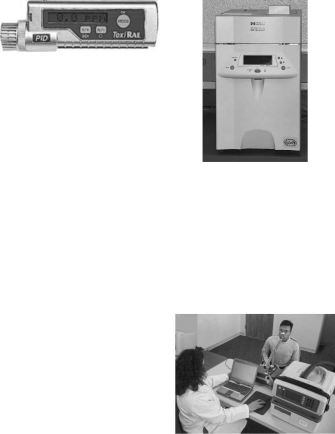
Figure 3. Seito ToxiRae personal PID gas monitor.
An inert gas lamp provides the UV light, (e.g., xenon lamps emit UV light at 147.6 nm, krypton at 123.9 nm, and argon at 105.9 nm). An advantage is that the sensitivity to particular species or groups of compounds can be adjusted by adjusting the output power to match the distinct ionization potentials of analyte gases. Consequently, different sensor sets can be achieved. For example, amines, aromatic compounds, and benzene are highly detectable at 9.5 eV. Disease and other anomaly marker gases often found in the breath, such as acetone, ammonia, and ethanol, are detectable at 9.5 eV as well as 10.6 eV. Other, more complex, marker gases such as acetylene, formaldehyde, and methanol can be detected at 10.6 eV and 11.7 eV. Typically, the PID devices are fairly responsive, on the order of a few seconds, and do well with moderately low concentrations (e.g., 0.1 ppm isobutylene).
One of the nice things about PIDs is that they can be made very small in size, as shown in Fig. 3, which shows the Rae Systems, Inc. ToxiRae personal gas monitor (www.raesystems.com). Depending on the UV source, CO, NO, SO2, or NO2 can be read. It works with rechargeable batteries.
Thermal Conductivity Detectors (TCD) are used to detect and quantify gases that have large variations in thermal conductivity. Gases that are discriminated well are sulfur dioxide and chlorine, which have roughly onethird the conductivity of air to helium and hydrogen, which have six and seven times the conductivity of air. As heat transfer depends on three mechanisms, radiation, convection, and conduction, the actual TCD sensor itself must be designed in such a way that conduction dominates, which implies a very slow, constant, moving flow to minimize or stabilize convection effects and a radiation-shielded enclosure. Most arrangements use two identically heated coils of wire comprising two legs of a Wheatstone bridge, one coil in a reference gas tube and the other in the sample tube. When the thermal conductivity of the sample increases, the sample coil is cooled more than the reference, and its resistance changes (usually decreases), thereby generating a voltage difference across the bridge. TCDs are usually used in high concentration applications, as they do not have the sensitivity of other techniques. TCDs do very well when mounted at the exit of a GC where the separated gas analytes are expected to have large variations in thermal conductivity.
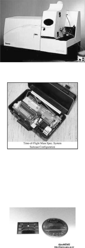
Gas chromatographs have come a long way over the last decade as far as size and cost are concerned. Although laboratory-grade devices such as the HP stand-alone system shown in Fig. 4 still are fairly common, portability is being stressed in order to get the almost incomparable
Figure 4. An HP/Agilent laboratory-grade gas chromatograph.
detectibilty of the GC to where the real gas problems exist, such as in the emergency or operating rooms, in the field, and at sites where toxins and suspected hazardous gases may be present. Bringing the GC to the patient or taking data without having subjects come into the lab has spawned systems such as Mensanna’s VOC (volatile organic compound) GC system that uses a PID (Fig. 5) to check trace gases in the breath, and HP’s has introduced a briefcase-sized micro-GC (Fig. 6). Lawrence Livermore National Laboratory has taken the recent developments in micromachining, MEMS (micro-electromechanical systems), and microfluidics and developed a real micro-GC. Researchers at LLNL (4) have micro-machined a very long capillary on a silicon chip, which serves as the separating column.
Figure 5. Mensanna portable GC for measuring breath VOCs.

Figure 6. Agilent (formerly HP) Micro-GC.
Figure 7 shows the implementation of this device that is reported to have a response time of less than 2 min.
INFRARED/OPTICAL SPECTROSCOPY
Gases absorb light or photon energy at different wavelengths depending on the complexity of their molecular structure. When a molecule is subjected to light energy of a particular frequency, the atoms involved in the atomic bonds will vibrate at the light frequency. If the frequency matches their resonant frequency, or a harmonic, they will resonate, thereby becoming highly absorbent as more of the light energy is used to feed the motion of the resonating molecules. The more complex a molecule, the greater number of different atomic bonds it will have and, consequently, the more absorption frequencies it will have. Table 1 provides some guidelines for absorption for different molecules.
Most infrared analyzers measure concentrations of volatile fluorocarbon halogenated anesthetic agents, carbon dioxide, and nitrous oxide using nondispersive infrared (NDIR) absorption technology. The transduction means may differ. Most use an electronic IR energy detector of one sort or another, such as a bolometer, solid-state photon detectors, and thermopiles; however, one monitor uses
Figure 7. LLNL MEMS-based micro-GC.
MEDICAL GAS ANALYZERS |
327 |
Table 1. Infrared Absorption Bands for Gases of Medical Interest
Wavelength |
Elements of Atomic |
Typical |
(microns) |
Bonds |
Gases |
|
|
|
2.7–4 mm |
X-H (X ¼ C, N, O, S) |
H2O, CH4, |
4.3–5 mm |
C-X (X ¼ C, N, O) |
CO2, N2O |
5.26–6.6 mm |
C-X (X ¼ C, N, O) |
fluorocarbons |
7.7–12.5 mm |
C-X (X ¼ C, N, O) |
fluorocarbons |
another IR detection principle, photoacoustic spectroscopy, based on the level of sound produced when an enclosed gas is exposed to pulsed/modulated IR energy.
Infrared analyzers have been used for many years to identify and assay compounds for research applications. More recently, they have been adapted for respiratory monitoring of CO2, N2O, and halogenated anesthetic agents.
Dual-chamber NDIR spectrometers pass IR energy from an incandescent filament through the sample chamber and an identical geometry but air-filled reference chamber. Each gas absorbs light at several wavelengths, but only a single absorption wavelength is selected for each gas to determine the gas concentration. The light is filtered after it passes through the chambers, and only that wavelength selected for each gas is transmitted to the detector. The light absorption in the analysis chamber is proportional to the partial pressure (concentration) of the gas. Most manufacturers use a wavelength range around 3.3 mm, the peak wavelength at which the hydrogen-carbon bond absorbs light, to detect halogenated anesthetic hydrocarbons (halothane, enflurane, isoflurane, etc.).
In one monitor that identifies and quantifies halogenated anesthetic agents, the analyzer is a single-channel, four-wavelength IR filter photometer. Each of four filters (one for each anesthetic agent and one to provide a baseline for comparison) transmits a specific wavelength of IR energy. Each gas absorbs differently in the selected wavelength bands so that the four measurements produce a unique signature for each gas. In another monitor, potent anesthetic agents are assessed by determining their absorption at only three wavelengths of light. Normally, only one agent is present so this process reduces totagent ID. However, the use of ‘‘cocktails,’’ mixtures of agents, usually to reduce undesired side effects of one or another agent, require very special monitoring because of the possibility of accidental overdosing.
The Datex-Ohmeda Capnomac (www.us.datexohmeda.com), a multigas anesthetic agent analyzer, is based on the absorption of infrared radiation. This unit accurately analyzes breath-to-breath changes in concentrations of CO2, NO2, and N2O and anesthetic vapors. It is accurate with CO2 for up to 60 breaths/min, and 30 breaths/ min for O2 (using a slower paramagnetic sensor), but N2O and anesthetic vapors show a decrease in accuracy at frequencies higher than 20 breaths/min. The use of narrow wave-band filters to increase specificity for CO2 and N2O makes the identification of the anesthetic vapors, which are measured in the same wave band more difficult. It is interesting to note that IR spectroscopy can also be used on

328 MEDICAL GAS ANALYZERS
liquids, as exemplified by the Inov 3100 near-infrared spectroscopy monitor that has been offered as a monitor for intracerebral oxygenation during anesthesia and surgery. Studies with this monitor indicate that it needs a wide optode separation and the measurements are more likely those of the external carotid flow rather than the divided internal carotid circulation (5).
A subset of NDIR is photoacoustic spectroscopy, which measures the energy produced when a gas expands by absorption of IR radiation, which is modulated at acoustic frequencies. A rotating disk with multiple concentric slotted sections between the IR source and the measurement chamber may be used tmodulate the light energy. The acoustic pressure fluctuations created occur with a frequency between 20 and 20,000 Hz, producing sound that is detected with a microphone and converted totan electrical signal. Each gas (anesthetic agent, CO2, N2O) exhibits this photoacoustic effect most strongly at a different wavelength. This method cannot distinguish which halogenated agent is present, however. The microphone detects the pulsating pressures from all four gases simultaneously and produces a four-component magnetic signal. A monitor using IR photoacoustic technology has been developed that can quantify all commonly respired/anesthetic gases except N2 and water vapor. Similarly, a microphone detects the pulsating pressure changes in a paramagnetic oxygen sensor (magnetoacoustics).
The Bruel & Kjaer Multigas Monitor 1304 (6) measurements use photoacoustic spectroscopy and also incorporate a pulse oximeter. It has some advantages over the Datex Ohmeda Capnomac because it uses the same single microphone for detection of all gases, displaying gas concentration in real-time.
With the development of both fixed frequency and tunable solid-state lasers, a revolution in IR spectroscopy has occured with new technical approaches appearing every year. Tuned diode laser spectroscopy, and Laser-induced Photo Acoustic Spectroscopy (a DARPA initiative) are developments that bear close watching as they mature. The ability to produce IR energy at extremely narrow bandwidths allows discrimination of very closely related gas species such as CO2 and N2O. In addition, most of the volatile anesthetic agents such as halothane, desflurane, isoflurane, and sevoflurane can also be thus distinguished.
An advantage of NDIR is that the sensing mechanism does not interfere or contact the sample, thus minimal chance exists that the sample would be affected. The costs of these devices have continued to decrease, with numerous companies competing to keep the prices low and attractive. Disadvantages are the susceptibility to dirt and dust in the optical path and cross-sensitivities to interfering gases.
Companies marketing anesthesia and respiratory mechanics monitors are involved in either development or promotion of NDIR. Figure 8 shows a Datex-Ohmeda Capnomac Ultima that uses NDIR for CO2, N2O and anesthetic analysis, and agent identification. The top waveform is the plethysmograph, the next down is the O2 (measured with a fast paramagnetic sensor), and the bottom waveform is the capnographic CO2 waveform. As an added capability beyond gas analysis, to the right of the
Figure 8. A Datex-Ohmeda Capomac Ultima multiple gas analyzer.
capnogram is the pressure-volume loop that is used to assess the lung compliance.
Another limitation of NDIR is its relatively low sensitivity due, for the most part, to the short path length over which the IR energy is absorbed. The short path length and small chamber size is dictated by the need for fast response in order to be able to monitor human physiological and respiratory response.
Breath rates are normally about 10 breaths per min (bpm) but, under acute hyperventilation conditions, can reach 100 bpm and higher. Also, neonates and small animals naturally exhibit high breathing rates, which requires a sensor with a millisecond response in order to be able to detect breath-by-breath variations. However, in cases where a fast response is not the driving factor, the sampling chamber may be lengthened or the path length increased.
Notwithstanding this limitation, the recent invention of Cavity Ring-Down Spectroscopy (CRDS) by Princeton chemist Kevin Lehmann (7,8) is based on absorption of laser energy over huge path lengths but is extremely fast. By bouncing laser energy between near-perfect mirrors in a sample or test chamber, the light can pass through the gas of interest multiple times, often for total distances of up to 100 km, which creates the opportunity to detect miniscule trace amounts of the gas species of interest. The time it takes for the light energy to get attenuated to zero provides a measure of the amount of the gas species present. The shorter the Ring-Down time, the more of the gas is present. These times are, however, on the order of only milliseconds. In fact, Tiger Optics of Warrington, PA, the company that has licensed Dr. Lehmann’s technological development, claims that trace gases can be detected in the hundreds of parts per trillion. The LaserTrace multi-point, multi-species, multi-gas analyzer (shown in Fig. 9) is capable of detecting many species such as H2O, O2, CH4, H2, CO, NH3, H2S, and HF. The O2 module measures down to 200 parts-per-trillion (ppt), in milliseconds, noninvasively and can readily be adapted to respiratory breath measurements. Methane can be detected at the parts per billion level.

Figure 9. Tiger Optics Cavity Ring-Down Spectrometer.
Although of interest in the detection and quantification of oxygen, spectroscopy has not been widely considered for this application. However, an oxygen absorption line exist in the center of the visible spectrum at 760 nm. Often neglected because of the problems associated with the narrowness of the absorption band (0.01 nm versus 100 nm for CO2 in the IR) as well as with spurious interference from visible light, it is nonetheless an opportunity because no interference exists from any other gases of medical interest. The development of low cost, very nar- row-band lasers has resulted in the successful introduction of Laser-based Absorption Spectroscopy from Oxigraf (www.oxigraf.com). With 100 ms response and 0.02% resolution traces, such as that shown in Fig. 10, are possible. Cost is relatively low in comparison with other technical approaches with similar capabilities.
LUMINESCENCE/FLUORESCENCE
Gas sensors that use luminescence or fluorescence basically take advantage of the phenomenon of excitation of a molecule and the subsequent emission of radiation. Photoluminescence implies optical excitation and re-emission of light at a different, lower frequency. Chemiluminescence implies the emission of light energy as a result of a chemical reaction. In both cases, the emitted light is a function of the presence of the gas species of interest and is detected by optical means. Most industrial sensors use photomultiplier tubes to detect the light, but the needs of the medical community are being met with more compact fiber-optic systems and solid-state photodetectors.
Fluorescence quenching is a subset of luminescencebased sensors, the difference being that the presence of the analyte, rather than stimulating emission of light,
Figure 10. Oxigraf Fast Oxygen Sensor trace of respired O2.
MEDICAL GAS ANALYZERS |
329 |
actually diminishes the light output. Fundamentally, fluorescence occurs when incoming light excites an electron in a fluorescent molecule to a higher energy state, and, in turn, when the electron returns to its stable state, it releases energy in the form of light.
Two important characteristics of fluorescence are that the light necessary to excite a fluorescent molecule has a shorter wavelength than that of the fluorescent emission, and that the fluorescence of a particular molecule may be suppressed (quenched) or enhanced (dequenched) by the presence of one or more specific molecules. Consequently, the presence of such other molecules (called analytes) may be detected.
A few companies exist that use one form or another of luminescence sensing, in particular, of oxygen in the medical arena, although the sensors are ubiquitous for other gases. For example, Ocean Optics (www.oceanoptics.com) FOXY Fiber Optic Oxygen Sensors use the fluorescence of a ruthenium complex in a sol-gel to measure the partial pressure of oxygen. First, a pulsed blue LED sends light, at 475 nm, to and through an optical fiber, which carries the light to the probe. The distal end of the probe tip consists of a thin layer of a hydrophobic sol-gel material. A ruthenium complex is trapped in the sol-gel matrix, effectively immobilized and protected from water. The light from the LED excites the ruthenium complex at the probe tip and the excited ruthenium complex fluoresces, emitting energy at 600 nm. When the excited ruthenium complex encounters an oxygen molecule, the excess energy is transferred to the oxygen molecule in a nonradiative transfer, decreasing or quenching the fluorescence signal. The degree of quenching is a function of the level of oxygen concentration pressure in the film, which is in dynamic equilibrium with oxygen in the sample. Oxygen as a triplet molecule is able to efficiently quench the fluorescence and phosphorescence of certain luminophores. This effect is called ‘‘dynamic fluorescence quenching.’’ When an oxygen molecule collides with a fluorophore in its excited state, a nonradiative transfer of energy occurs. The degree of fluorescence quenching relates to the frequency of collisions and, therefore, to the concentration, pressure, and temperature of the oxygen-containing media. The energy is collected by the probe and carried through an optical fiber to a spectrometer where an analog-to-digital (A/D) converter converts the data to digital data for use with a PC.
MASS SPECTROSCOPY
Mass spectroscopy provides, what many consider, the best accuracy and reliability of all of the gas analyzing/assaying schemes. The basic concept is to assay the analyte by reducing it into ionized component molecules and separating them according to their mass-to-charge ratio. By this technique, the constituents of the sample gas are ionized. The resulting ions are accelerated through an electrostatic field and then passed through a deflecting magnetic field. The lighter ions will deflect more than the heavier ions. Detecting the displacement and counting the ions can achieve the assay of the gas sample.
330 MEDICAL GAS ANALYZERS
Ion detectors usually comprise an electric circuit where the impinging ions generate a current, which can be measured with a conventional circuit. The more current, the more ions are impinging. In practice, the ionization must be conducted in a high vacuum of the order of 10 6 torr. The gas is ionized with a heated filament, or by other means as have been discussed before.
A number of different mass spectroscopic configurations have been developed over the years. Time-of-flight (TOF) systems differ from the magnetically deflected devices in that the ions are free to drift across a neutrally charged evacuated flight chamber after having been accelerated electrostatically by a series of gratings that separate the ions. The time it takes for the ions to travel across the chamber is a function of their mass. An output not unlike that of a GC is developed. Quadrupole mass spectrometers focus the ions through an aperture onto a quadrupole filter. The ion-trap mass spectrometer traps ions in a small volume using three electrodes. An advantage of the ion-trap mass spectrometer over other mass spectrometers is that it has a significantly increased signal-to- noise ratio because it is able to accumulate ions in the trap. It also does not require the same kind of large dimensions that the TOF and magnetically deflected devices need, so, as a consequence, it can be made in a fairly compact size. Finally, the Fourier-transform mass spectrometer takes advantage of an ion-cyclotron resonance to select and detect ions. Single-focusing analyzers use a circular beam path of 1808, 908, or 608. The various forces influencing the particle separate ions with different mass-to-charge ratios. Double-focusing analyzers have an electrostatic analyzer added to separate particles with difference in kinetic energies.
A particular advantage of the mass spectrometer is that it can operate with an extremely small gas sample and can detect minute quantities. Response was long compared with most continuous sensors, but with the development of high speed microprocessors, analysis times have steadily decreased to where, today, it is not unusual to have assays in less than one minute. With the development of MEMS TOF devices, the time-of-flight is measured in microseconds.
Mass spectrometers have always tended to be bulky and expensive and, thus, rarely used on a single patient basis. Multiplexing up to 30 patients using a complex valving switching system has been shown to be feasible and has made the system much more cost-effective. Figure 11 shows a conventional ThermoElectron laboratory-grade mass spectrometer setup.
The move to miniature mass spectrometers has been rapid over the last decade, from a suitcase-sized miniature TOF mass spectrometer, developed at Johns Hopkins Applied Physics laboratory (Fig. 12) (9), to a micro-electro- mechanical system (MEMS) device smaller than a penny, developed in Korea at the MicroSystems Lab of Ajou University (Fig. 13) (10).
Mass spectroscopy is often used as the detector in combination with gas chromatography to enhance the sensitivity down to ppb, because in a GC, detection limits the capability.
Figure 11. A ThermoElectron laboratory-grade quadrupole mass spectrometer.
Figure 12. JHU Teeny mass spectrometer.
NUCLEAR MAGNETIC RESONANCE
Nuclear Magnetic Resonance (NMR) is the process by which a relatively low intensity radio-frequency (RF) signal at the resonant frequency of the species of gas of interest interacts with the atoms in a gas and aligns them momentarily, which requires some energy. When the RF
Figure 13. MEMS TOF mass spectrometers developed at Ajou University in Korea.
signal is removed, the atoms release the energy that had been stored in the alignment resonance, return to their chaotic orientations, and re-emit an RF signal at the same resonant frequency at which they were excited. Each atomic bond has its own characteristic frequency so that a spectroscopic analysis can be made by scanning through a large number of frequencies. A variant of NMR, nuclear quadrupole resonance (NQR) is used for detecting explosive vapors, which could be very useful in military medicine where explosives in clothing during triage pose a major hazard. The hydrogen bonds in TNT have a resonance at760 kHz and the vapors of plastic explosives have resonances at low MHz frequencies. NMR is very attractive because gas analysis can be performed without having to physically take a sample of the analyte in question. As the initiating and re-emitted RF signals can pass through most nonferrous materials with little attenuation, gas, liquid, and solid chemical species can be interrogated noninvasively. By summing the returns from a number of signals, sensitivity to the low ppm can be achieved.
In dirty environments where optical or infrared devices suffer significant degradation of performance, NMR is particularly useful. Compared with chromatographic approaches, NMR eliminates the need for solvents, columns, carrier gases, or separations. Also, NMR analysis can be performed in real-time because typical atomic relaxation times, the time it takes for the atomic spin axes to return to their original orientations, is on the order of milliseconds for many gases of interest.
PARAMAGNETISM
Many gases exhibit magnetic sensitivity, paramagnetism, due to their polar nature, which means that they are attracted to a magnetic field. For oxygen, its paramagnetic sensitivity is due to its two outer electrons in unpaired orbits. Most of the gases used in anesthesia are repelled by a magnetic field (diamagnetism).
Paramagnetic sensors are typically used specifically for measuring oxygen concentration. The high degree of sensitivity of oxygen (compared with other gases) to magnetic forces reduces the cross-sensitivity to other gases of paramagnetic sensors. Sensors come in two variants, the older balance type and the newer pressure type. The balance types of sensors are relatively frail and have been replaced by the pressure types. Nevertheless, some of these older devices are still being used. The balance type of sensor uses a mechanical approach that has a dried gas sample flowing through a chamber in which a nitrogen-filled dumbbell is balanced in a magnetic field. The paramagnetic force on the oxygen in the sample puts a torque on the dumbbell. The output can be read either as a spring-loaded displacement or, in newer devices, electronically by measuring the current required to keep the dumbbell centered.
Most modern paramagnetic oxygen sensors consist of a symmetrical, two-chambered cell with identical chambers for the sample and reference gas (often air or nitrogen). These cells are joined at an interface by a responsive differential pressure transducer or microphone. Sample and reference gases are pumped through these chambers
MEDICAL GAS ANALYZERS |
331 |
in which a strong, usually varying, magnetic field surrounding the region acts on the oxygen molecules and generates a static pressure or a time-varying (acoustic) difference between the two sides of the cell, causing the transducer to produce a DC or AC voltage proportional to the oxygen concentration. When the magnetic field is modulated at acoustic frequencies, these devices may sometimes be referred to as magnetoacoustic.
Paramagnetic oxygen analyzers are very accurate, highly sensitive, and responsive, often with a step response of 200 ms to 90% of maximum. However, they require calibration, usually with pure nitrogen and oxygen. A major drawback is that they are adversely affected by water vapor and, consequently, require a water trap incorporated into their design. The frequency response makes then useful for measurement of oxygen on a breath-by- breath basis. The Datex Ohmeda Capnomac Ultima that was previously shown in Fig. 8 uses a paramagnetic oxygen sensor, as do many of the other mainline medical gas monitor manufacturers.
RADIOACTIVE IONIZATION
The ubiquitous smoke detector found in every house, hospital, and facility has spawned detectors for other gases such as carbon monoxide, a very important marker gas in medical diagnosis. Although usually used as devices that are set to alarm when a preset level is detected, they are also used as calibrated sensors. A very low level radioactive alpha particle source (such as Americium-241) can ionize certain gases so that, in the presence of an analyte, a circuit can be completed and current caused to flow in the detector circuit.
Ionization detectors detect the presence of invisible particles (less than 0.01 micron in size) in the air. Inside the detector, a small ionization chamber exists that contains an extremely small quantity of radioactive isotope. Americium-241 emits alpha particles at a fairly constant rate. The alpha particles, which travel at an extremely high rate of speed, knock off an electron from the oxygen and nitrogen molecules in the air passing through the ionization chamber. The free electron (negative charge) is then attracted to a positively charged plate, and the positively charged oxygen or nitrogen is attracted to a negatively charged plate, which creates a very small but constant current between the plates of a detector circuit, which in itself is a gas detection mechanism much in the same way that the other ionization detectors operated. However, when particles, such as soot particles, dust, fumes, or steam, enter the ionization chamber, the current is disrupted. If the current decreases too mid, an alarm is triggered.
The disadvantage of these devices is clearly the health hazard associated with the presence of the radioactive material. However, because the detector contains only a tiny amount of radioactive material, exposure is unlikely with proper care in handling. Another disadvantage of these sensitive detectors is the false-positive alarms that can be triggered by spurious dust and other nontoxic fumes. However, the big advantage is that ionization detectors are very sensitive and, given that false alarms
332 MEDICAL GAS ANALYZERS
are tolerable, should be considered in most alarm situations.
Another form of radioactive detector is the electron capture detector, which uses a radioactive Beta emitter (electrons) to ionize some of the carrier gas and produce a current between a biased pair of electrodes. When organic molecules that contain electronegative functional groups, such as halogens, phosphorous, and nitro groups, pass by the detector, they capture some of the electrons and reduce the current measured between the electrodes.
RAMAN LASER SPECTROSCOPY
In the 1980s, Raman scattering was first heralded as an improvement to mass spectrometry (11), although some individuals had reservations (12). Although no longer manufactured but still serviced, Ohmeda Rascal II multi-gas analyzer uses a Raman scattering of laser light to identify and quantify O2, N2, CO2, N2O, and volatile anesthetic agents. It is stable and can monitor N2 directly and CO2 accurately for a wide range of concentrations. One of the acknowledged disadvantages is that a possibility of some destruction of volatile anesthetic agent exists during the analysis because the concentration of halothane does appear to fall when recirculated and as much as 15% must be added. Some concern exists over the reliability of the hardware, software, and laser light source (13) that is currently being addressed by others.
Raman scattering occurs when a gas sample is drawn into an analyzing chamber and is exposed to a high intensity beam from an argon laser. The laser energy is absorbed by the various molecules in the sample and are then excited into unstable vibrational or rotational energy states, which is the Raman scattering. The low intensity Raman scattered, or re-emitted, light signals are measured at right angles to the laser beam, and the spectrum of Raman scattering lines can be used to identify various types of gas molecules. Spectral analysis allows identification of known compounds by comparison with their Raman spectra. This technique is of similar accuracy to mass spectrometry.
SOLID-STATE SENSORS
At least four types of solid-state gas sensors exist: semiconductor metal oxide (SMO) sensors; chemically sensitive field effect transistors (ChemFETs); galvanic oxide sensors; and piezoelectric or surface acoustic wave (SAW) crystal sensors.
Semiconductor metal sensors are an outgrowth of the development of semiconductor devices. Early in the development of transistors and integrated circuits, it was observed that the characteristics would change in the presence of different gases. Recalling that a transistor is basically a voltage-controlled resistor, it was discovered that the p-n junction resistance was being changed by chemical reaction with the semiconductor materials (14). Commercially available Taguchi Gas Sensors (TGS) tin oxide sensors have found a niche as electronic noses. Walmsley et al. (15) used arrays of TGS sensors to develop
patterns for ether and chloroform and other vapors of medical interest.
Hydrocarbons were among the first gases to be detected, and later, hydrogen sulfide was found to be detectable. Since the first tin oxide sensors appeared in the late 1960s, it has been found that by doping transition metal oxides, such as tin and aluminum, with other oxides, that as many as 150 different gases could be specifically detected (1) at ppm levels. The heated oxide adsorbs the analyte and the resistance change is a function of the concentration of the analyte. The semiconducting material is bonded or painted in a paste to a nonconducting substrate and mounted between a pair of electrodes. The substrate is heated to a temperature such that the gas being monitored reversibly changes the conductivity of the semiconducting metal oxide material. When no analyte is present, the current thinking is that oxygen molecules capture the free electrons in the semiconductor material when they are absorbing on the surface, thereby preventing the mobility of the electron flow. Analyte molecules replace the oxygen, thereby releasing the free electrons and, consequently, reducing the SMO resistance between the electrodes.
The ChemFET is derived from a field effect transistor where the normal gate metal has been replaced with a catalytic metal or chemically sensitive alloy. The gaseous analyte interacts with the gate metal and changes the FET characteristics to include gain and resistance.
Solid-state galvanic cells are based on the semiconductor galvanic properties of certain oxides or hydrides. The zirconium oxide galvanic cell oxygen sensor is probably one of the most ubiquitous sensors in daily life. It is the sensor mounted in every automobile catalytic converter to measure its effectiveness. Zirconium oxide, when heated to a temperature of about 700 8C, becomes an oxygen ion conductor, so that, in the presence of a difference in partial pressure on either side of a tube with metallized leads coming off each side, a voltage potential (Nernst voltage) is developed. These devices are commonly called fugacity sensors. As the process is reversible, a voltage applied will cause oxygen ions to flow. This process may also be applicable to the hydrogen ions in hydrides. An advantage of these oxygen sensors over other types is that no consumable exists. Hence, life is long. However, the need for heating tends to make these devices difficult to handle and they, as well as SMOs, require significant power to power the heating elements. However, because these sensors can be very small, they can have fast response times, often less than 100 ms, which makes them suitable for use for respiration monitoring. The electronics associated with the detection circuits is simple and should be very reliable.
Piezoelectric sensors use the change in a crystal vibrational frequency or propagation of surface acoustic waves to measure the concentration of a selected analyte. Most often, an analyte sample is passed through a chamber containing two piezoelectric crystals: a clean reference crystal and a second crystal that has been coated with a compound that specifically adsorbs specific analyte gases. Organophillic coatings are used for hydrocarbons such as anesthetic vapors. The resulting increase in mass changes the coated crystal’s resonant frequency or the speed of propagation in direct proportion to the concentration of
anesthetic gas in the sample. Using either some form of beat frequency measurement or detection of the phase shift between the two crystals, a detection circuit can generate a signal that can be processed and displayed as a concentration.
EMERGING TECHNOLOGIES—MEMS—
MICROFLUIDICS–NANOTECHNOLOGY
The development of a variety of microfluidic labs-on-a-chip is leading the charge in the state-of-the-art in gas sensing. It was noted in the gas chromatography section that microfluidic channels are being used as GC columns and in the mass spectrometry section that microfluidics plays a major role in the TOF passages and chambers. The ability to miniaturize classic technologies has opened the door to mass production as well as the ability to mix-and-match sensors and technologies. The development of electronic noses that can discriminate between thousands of different chemicals and gases is driving the need to detect odors and minute quantities of dangerous or toxic gases.
Patient safety in medicine continues to be a major driver. MEMS (micro-electromechanical systems) and nanotechnology have become the enabling technologies for placing thousands of sensors in microdimensional arrays that can be placed inside a capsule and swallowed or implanted to monitor physiological and metabolic processes. IR bolometers that can sense incredibly small temperature differences as low as 0.02 8C are already a part of today’s inventory (Fig. 14), and in the future, nanotechnology elements that are merely one molecule thick and dust particle-sized may provide IR spectroscopic capability in implantable or inhaled micro-packages.
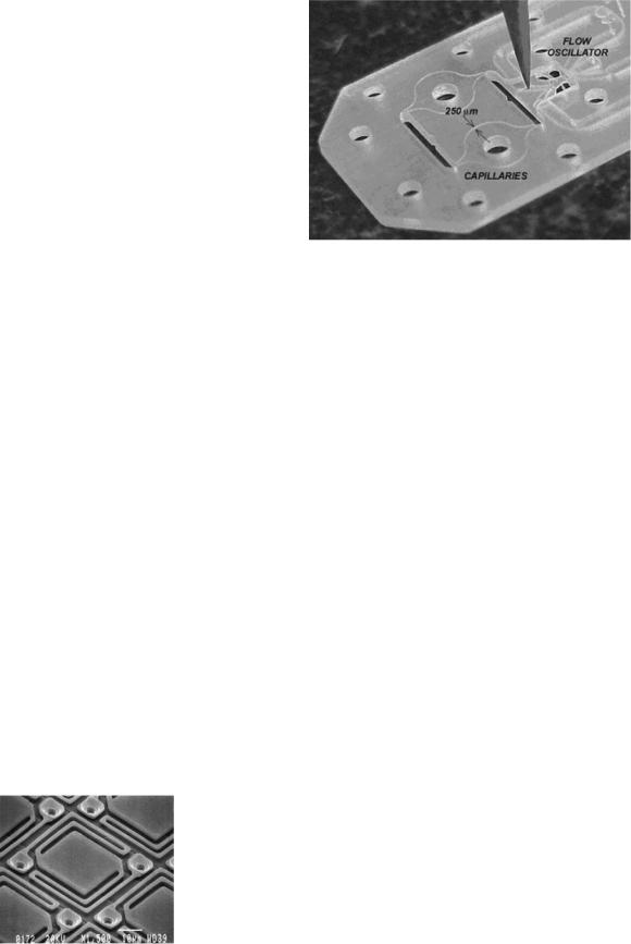
A new paradigm for gas analysis that has been enabled by the development of microfluidics was originally suggested in the 1960s by Mapleson (16), who suggested measuring a physical gas property as a way of inferring binary gas mixture composition. This concept has been extended and implemented for ternary and quaternary gas mixtures with a microfluidic gas multiple gas property analyzer (17–20). Ternary mixtures are assayed with a chip that measures viscosity with a microcapillary viscometer and density with a micro-orifice densitometer. An early prototype microfluidic lab-on-a-chip showing the microcapillaries is shown in Fig. 15. By measuring properties possessed in common by all gases, such as density, viscosity, and specific heat, a single chip can be used to
Figure 14. 25 micron wide longwave IR microbolometer detector.
MEDICAL GAS ANALYZERS |
333 |
Figure 15. Microfluidic chip that measures the density and viscosity of three-component respired gases from which the constituent gas concentrations of oxygen, nitrogen, and carbon dioxide are deduced.
analyze mixtures of any four gases. The concentrations of the constituents can be determined by simultaneously solving the equations that relate the mixture properties to the concentrations, thereby determining the relative concentrations of the mixture gases required to produce the measured properties. The only limitation to such an approach is that one must know what at least all but one of the constituents are. Microfluidic property sensors such a capillary viscometers, orifice densitometers, and speed-of- sound calorimeters can provide real-time simultaneous assays of respiratory gases (O2, CO2, and N2), the simultaneity of which then enables the reduction to practice of a variety of physiologic analyzers such as metabolic rate, cardiac output, and cardio-pulmonary function that had been postulated back in the 1960s (21) but never practically implemented.
Advances in optics and optical fiber technology, greater expansion of solid-state sensing, and the revolutionary aspects of nanotechnology will provide gas analysis and sensing with new capabilities, provided that the lessons learned from the past are appropriately heeded.
OTHER CONSIDERATIONS IN GAS ANALYSIS
Most continuous gas analysis devices are side-stream monitors that acquire gas samples from a breathing circuit through long, narrow-diameter tubing lines. These lines may incorporate moisture removal to allow moisture to pass through the sampling line and into the atmosphere, as is the case with Nafion tubing. A water trap or filter may also be used to remove condensation from the sample in order to reduce water vapor before the gas sample reaches the analysis chamber. Gas samples are aspirated into the monitor at either an adjustable or a fixed-flow rate, typically from 50 to 250 ml/min. Lower rates minimize the amount of gas removed from the breathing circuit and, therefore, from the patient’s tidal volume; however, lower sampling flow rates increase the response time and typically reduce the accuracy of conventional measurements.
334 MEDICAL GAS ANALYZERS
Gas monitors have to eliminate the exhaust gas through a scavenging system or back to the patient’s breathing circuit.
DISPLAYS, ALARMS, CALIBRATION, AND CONTROLS
Many gas monitors provide a graphic display of breath-by- breath concentrations and a hardcopy of trends of gas concentrations from the beginning to the end of an event (e.g., anesthesia delivery during an operation). The user typically calibrates or verifies calibration of the sensors with a standard gas mixture from an integral or external gas cylinder. Gas monitors are usually microprocessorcontrolled and have user-adjustable alarms that typically include factory-preset default alarms or alarm-set programs for both high and low concentrations of the gases measured. Some monitors also have alarms for system malfunctions, such as disconnection from a gas source, and leaks can often be identified from trending of O2 and CO2. Occlusion, apnea, or inadvertent rebreathing can also be identified. Most monitors typically have a method for temporarily, but not indefinitely, silencing audible alarms for low O2, high N2O, and high agent, whereas other, less critical audible alarms can be permanently silenced. Most monitors typically display real-time waveforms and long-term trends. They have integral display capability and are also commonly equipped with output jacks to interface with computerized record-keeping systems or with additional analog or digital display units such as chart recorders and printers.
PATIENT SAFETY
A review of the background and significance of medical gas sensors and monitors would be incomplete without an expression of the context that patient safety has had on the impetus for recent gains in technology and the need for additional improvements. Clearly the intrinsic dangers in the conduct of anesthesia have been long understood. It became evident in the early 1980s that patient safety and reduction to risk was possible if respiratory and anesthetic gas monitoring was routinely available and used. As a result of improved and increased availability of medical gas monitoring technology and professional activity lead by the Anesthesia Patient Safety Foundation (APSF) with the support of the American Society of Anesthesiologists (ASA), a standard for monitoring has been adopted and is routinely used in today’s clinical practice. This standard requires assessment of the patient’s ventilation and oxygenation in addition to circulation and temperature. The use of such monitors has resulted in a significant decrease in the risk of anesthesia-related deaths and morbidity in the ICU and other critical care situations.
CONCLUSION
Medical gas monitoring has been so successful in improving patient safety and reducing patient risk that medical malpractice liability insurance companies have lowered
their risk liabilities and premiums to anesthesiologists who guarantee the routine implementation of these standards whenever possible (22). The argument for providing additional patient safety will continue to be a powerful incentive to improve and enhance the methods and techniques to provide increased knowledge of the monitoring of respiratory and anesthetic gases.
The availability of gas sensors and monitors is a boon to the medical profession from both a clinical as well as a research point of view. In addition to patient safety, new diagnostic capabilities are emerging every year. In research, new gas-sensing capabilities are enhancing the discovery of markers for all kinds of disease states and metabolic functions.
Looking to the future, MEMS, microfluidics, and nanotechnology will provide growth in our understanding of physiologic processes at levels of detail never before conceived of, from inside the body as well as supplanting today’s conventional techniques.
BIBLIOGRAPHY
1.Chou J, Hazardous Gas Monitors, A Practical Guide to Selection, Operation and Applicationsy. New York: McGraw-Hill; 2000.
2.ECRI. Multiple medical gas monitors, respired/anesthetic. Product Comparison System, ECRI Product Code 17–445, August 1993.
3.Datex Ohmeda Smart Vent 7900. Product Description AN2842-B/7 01 1999 Datex-Ohmeda, Inc.
4.Yu CM, Sheem SK. (1995). Miniature gas chromatography sensor. Lawrence Livermore National Lab. www.llnl.gov/sensor_technology/STR72.html.
5.Harris D, Bailey S. Near infrared spectroscopy in adults. Anaesthesia 1993;48:694–696.
6.McPeak HB, Palayiwa E, Robinson GC, Sykes MK. An evaluation of the Bruel and Kjaer monitor 1304. Anaesthesia 1992; 47(1):41–47.
7.Lehmann KK, Rabinowitz P. High-finesse optical resonator
for cavity ring-down spectroscopy based upon Brewster’s angle prism retroreflectors. U.S. Patent 5,973,864, October 26, 1999.
8.Lehmann KK, Romanini D. The superposition principle and cavity ring-down spectroscopy. J Chem Phys 1996;105(23): 10263–10277.
9.Ecelberger SA, Cornish TJ, Bryden W. The improved teenyTOF mass spectrometer for chemical and biological sensing, 3rd Harsh-Environment Mass Spectrometry Workshop, March 25–28, 2002 Pasadena, CA.
10.Yoon HY, Kim JH, Choi ES, Yang SS, Jung KW. Fabrication of a novel micro time-of-flight mass spectrometer. Sens Actuators A 2002;97–98:441–447.
11.Westenskow DR, Smith KW, Coleman DL, et al. Clinical evaluation of a Raman scattering multiple gas analyzer. Anesthesiology 1989;70:350–355.
12.Severinghaus JW, Ozanne GM. Multi-operating room monitoring with one mass spectrometer. Acta Anaesthesiol Scan 1987; (Suppl) 70:186–187.
13.Lockwood G, Landon MJ, Chakrabarti MK, Whitwam JG. The Ohmeda Rascal II. Anaesthesia 1994;49:44–53.
14.Kress-Rogers E, ed. Handbook of Biosensors and Electronic Noses—Medicine, Food and the Environment. Boca Raton, FL: CRC Press; 1996.