

Wasserscheid P., Welton T. - Ionic Liquids in Synthesis (2002)(en)
.pdf56Robert A. Mantz, Paul C. Trulove
3.2
Viscosity and Density of Ionic Liquids
Robert A. Mantz and Paul C. Trulove
3.2.1
Viscosity of Ionic Liquids
The viscosity of a fluid arises from the internal friction of the fluid, and it manifests itself externally as the resistance of the fluid to flow. With respect to viscosity there are two broad classes of fluids: Newtonian and non-Newtonian. Newtonian fluids have a constant viscosity regardless of strain rate. Low-molecular-weight pure liquids are examples of Newtonian fluids. Non-Newtonian fluids do not have a constant viscosity and will either thicken or thin when strain is applied. Polymers, colloidal suspensions, and emulsions are examples of non-Newtonian fluids [1]. To date, researchers have treated ionic liquids as Newtonian fluids, and no data indicating that there are non-Newtonian ionic liquids have so far been published. However, no research effort has yet been specifically directed towards investigation of potential non-Newtonian behavior in these systems.
Experimentally determined viscosities are generally reported either as absolute viscosity (η) or as kinematic viscosity (υ). Kinematic viscosity is simply the absolute
viscosity normalized by the density of the fluid. The relationship between absolute viscosity (η), density (ρ), and kinematic viscosity (υ) is given by Equation 3.2-1.
ηρ = υ |
(3.2-1) |
The unit of absolute viscosity is the Poise (P, g cm–1s–1 or mPa s), while the unit for kinematic viscosity is the Stoke (St, cm2s–1). Because of the large size of these viscosity units, absolute viscosities for ionic liquids are usually reported in centipoises (cP) and kinematic viscosities reported in centistokes (cSt).
3.2.1.1Viscosity measurement methods
The viscosities of ionic liquids have normally been measured by one of three methods: falling ball, capillary, or rotational. Falling ball viscometers can easily be constructed from a graduated cylinder and appropriately sized ball bearings. The ball bearing material and the diameter can be varied. The experiment is conducted by filling the graduated cylinder with the fluid to be investigated and carefully dropping the ball through the fluid. After the ball has reached steady state, the velocity is measured. The absolute viscosity can then be calculated by Stokes’ law (Equation 3.2-2) [1]:
|
2 |
(ρs |
− ρ)gR2 |
|
|
η = |
|
|
|
ν |
(3.2-2) |
|
|
||||
|
9 |
|
|
|
|

3.2 Viscosity and Density of Ionic Liquids 57
where η is the absolute viscosity, ρs is the density of the ball, ρ is the density of the fluid, g is the gravity constant (980 cm s–2), R is the radius of the ball, and υ is the steady-state velocity of the ball. A falling ball viscometer is commonly calibrated with a standard fluid similar in viscosity to the fluid of interest, and an instrument constant (k) is then determined. Comparisons between the standard fluid and the unknown fluid can then be made by means of Equation 3.2-3
υ = k (ρs − ρ)θ |
(3.2-3) |
where θ is the time of fall between two fiducial marks on the viscometer tube. This technique does have several limitations: the fluid must be Newtonian, the density of the fluid must be known, and the downward velocity of the ball should not exceed ~1 cm s–1 to aid in time measurement. The falling ball method is generally used to measure absolute viscosities from 10–3 to 107 P [2].
Capillary viscometers are simple and inexpensive. They are normally constructed from glass and resemble a U-tube with a capillary section between two bulbs. The initial design originated with Ostwald and is shown as part A in Figure 3.2-1. The Cannon–Fenske type, a popular modification of the Ostwald design that moves the bulbs into the same vertical axis, is shown as part B in Figure 3.2-1.
A |
B |
|
Fiducial |
|
Marks |
Figure 3.2-1: Diagrams of (A) Ostwald and (B) Cannon–Fenske capillary viscometers.

58 Robert A. Mantz, Paul C. Trulove
Capillary viscometers are normally immersed in a constant-temperature bath, to regulate the sample temperature precisely during the experiment. To determine the viscosity, the fluid in the viscometer is drawn into the upper bulb by vacuum. The vacuum is released, and the time for the fluid to fall past the marks above and below the bulb is measured. The main driving force for flow in this type of viscometer is gravity, although pressure can be applied to one side of the viscometer to provide an additional driving force (increased head pressure) [1]. Since the driving pressure is governed by the difference in heights of the liquid in the viscometer, it is important always to use the same volume of liquid in each experiment. The kinematic viscosity can be calculated by Equation 3.2-4 [2];
|
πg (z1 − z2 ) D4 |
|
|
|
ν = |
|
|
∆t |
(3.2-4) |
128LVo |
|
|||
|
|
|
|
|
where (z1 – z2) is the difference in height, D is the capillary inner diameter, L is the length of the capillary, and Vo is the volume between the fiducial marks. This equation only holds as long as the liquid behaves as a Newtonian fluid and the length- to-diameter ratio of the capillary tube is large.
Capillary viscometers measure the kinematic viscosity directly, because the head pressure is generated by the weight of the fluid. In order to convert to absolute viscosity, the kinematic viscosity must be multiplied by the fluid density [Equation (3.2-1)]. Obviously this requires additional experiments to determine fluid density so that the absolute viscosity can be calculated. The capillary type viscometer is normally used to measure kinematic viscosities spanning the range from 4 × 10⁻³ to 1.6 × 10² Stokes, with experimental times ranging from 200 to 800 seconds [1]. This range of kinematic viscosities corresponds to absolute viscosities of 6 × 10⁻³ to 2.4 × 10² P, assuming an average ionic liquid density of 1.5 g cm–3.
The last type of widely used viscometer is the rotational viscometer. These can adopt a variety of geometries, including concentric cylinders, cone and plate, and parallel disks. Of the three geometries, the concentric cylinders is the most common, because it is well suited for low-viscosity fluids [2]. Rotational viscometers consist of two main elements: a rotating element and a fixed element. The liquid to be measured is placed in the space between the two elements. The viscosity is determined by measurement of the torque transferred between the two elements by the liquid. For the concentric cylinder geometry, the outer cylinder is often rotated at a fixed speed and the torque is measured on the fixed center cylinder immersed in the liquid. By measuring the angular speed of the rotating cylinder and the torque on the fixed cylinder, the fluid viscosity can be calculated by Equation 3.2-5 [2]:
|
|
|
2 |
|
|
|
(3.2-5) |
|
|
|
b |
|
−1 |
T |
|||
h = |
|
|
|
|
|
|
|
|
|
|
|
|
|
|
|
||
|
4pR22 Le w |
2 |
|
|||||
|
|
|
|
|
|
|
||
where β is the ratio of the cylinder radii, R2 is the radius of the outer cylinder, Le is the effective length of the cylinder, T is the torque applied to the rotating cylinder, and ω2 is the rotational speed of the outer cylinder [2]. The effective length of the

3.2 Viscosity and Density of Ionic Liquids 59
cylinder (Le) consists of the immersion depth of the center cylinder plus an end effect correction. This equation requires β to be less than 1.2.
All three methods discussed above appear to provide equally high quality ionic liquid viscosity data. However, the rotational viscometer could potentially provide additional information concerning the Newtonian behavior of the ionic liquids. The capillary method has been by far the most commonly used to generate the ionic liquid viscosity data found in the literature. This is probably due to its low cost and relative ease of use.
3.2.1.2Ionic liquid viscosities
As a group, ionic liquids are more viscous than most common molecular solvents. Ionic liquid viscosities at room temperature range from a low of around 10 cP to values in excess of 500 cP. For comparative purposes, the viscosities of water, ethylene glycol, and glycerol at room temperature are 0.890, 16.1, and 934 cP, respectively [3]. The room-temperature viscosity data (also conductivity and density data) for a wide variety of ionic liquids are listed in Tables 3.2-1, 3.2-2, and 3.2-3. These tables are organized by the general type of ionic liquid. Table 3.2-1 contains data for nonhaloaluminate alkylimidazolium ionic liquids, Table 3.2-2 for the haloaluminate ionic liquids, and Table 3.2-3 for other types of ionic liquids. There are multiple listings for several of the ionic liquids in Tables 3.2-1–3.2-3. These represent measurements by different researchers and have been included to help emphasize the significant variability in the viscosity data found in the literature.
The viscosities of many ionic liquids are strongly dependent upon temperature. For example, the viscosity of 1-butyl-3-methylimidazolium hexafluorophosphate increases 27 % with a 5 degree change between 298 and 293 K [16]. Clearly some of the apparent variability in the literature data seen in Tables 3.2-1–3.2-3 may have resulted from errors associated with control of experimental temperature. However, much of this variability is probably the result of impurities in the ionic liquids. Recent work with non-haloaluminate alkylimidazolium ionic liquids has established the ubiquitous nature of impurities in these ionic liquids, and has demonstrated the dramatic impact relatively that small amounts of impurities can have on ionic liquid viscosity [28]. In this study, a series of ionic liquids were prepared and purified by a variety of techniques. They were then analyzed for impurities and their physical properties evaluated. Chloride concentrations of up to 6 wt. % were found for some of the preparative methods. Residual chloride concentrations of between 1.5 and 6 wt. % increased the observed viscosity by between 30 and 600 % [28]. This work also showed the strong propensity of the non-haloaluminate alkylimidazolium ionic liquids to absorb water from laboratory air, and the significant solubility of water in these same ionic liquids (up to 14 wt. % for one ionic liquid). Surprisingly, as little as 2 wt. % (20 mol %) water (as well as other co-solvents, vide infra) reduced the observed viscosity of [BMIM][BF4] by more than 50 %. Given this information, it is highly likely that many of the ionic liquids listed in Table 3.2-1 (and by analogy Tables 3.2-2 and 3.2-3) contained significant concentrations of impurities (especially water). This, in turn, complicates the evaluation of the literature data, and any conclusions drawn below must consequently be used with care.

Table 3.2-1: Specific conductivity data for non-haloaluminate alkylimidazolium-based ionic liquids.
Cation |
Anion |
Temperature |
Conductivity |
Conductivity |
Viscosity |
Viscosity |
Density |
Density |
Molar |
Walden |
Ref. |
|
|
(K) |
(κ), mS cm–1 |
method |
(υ), cP |
method |
(ρ), g cm–3 |
method |
Conductivity |
product |
|
|
|
|
|
|
|
|
|
|
(Λ),cm2Ω–1mol–1 |
(Λη) |
|
|
|
|
|
|
|
|
|
|
|
|
|
[MMIM]+ |
[(CF3SO2)2N]– |
293 |
8.4 |
B |
44 |
R |
1.559 |
U |
2.03 |
89.44 |
4 |
[EMIM]+ |
[BF4]– |
295 |
12 |
I |
|
|
|
|
|
|
5 |
[EMIM]+ |
[BF4]– |
298 |
14 |
B |
34 |
U |
1.240 |
U |
2.24 |
76.22 |
6 |
[EMIM]+ |
[BF4]– |
298 |
14 |
I |
32 |
R |
1.279 |
I |
2.17 |
68.91 |
7a |
[EMIM]+ |
[BF4]– |
299 |
13 |
B |
43 |
R |
|
|
|
|
8 |
[EMIM]+ |
[BF4]– |
303 |
20 |
I |
|
|
|
|
|
|
9 |
[EMIM]+ |
[PF6]– |
299 |
5.2 |
B |
|
|
|
|
|
|
8 |
[EMIM]+ |
[CH3CO2]– |
293 |
2.8 |
B |
162 |
R |
|
|
|
|
4 |
[EMIM]+ |
[CF3CO2]– |
293 |
9.6 |
B |
35 |
R |
1.285 |
U |
1.67 |
58.62 |
4 |
[EMIM]+ |
[C3F7CO2]– |
293 |
2.7 |
B |
105 |
R |
1.450 |
U |
0.60 |
63.39 |
4 |
[EMIM]+ |
[CH3SO3]– |
298 |
2.7 |
B |
160 |
C |
1.240 |
V |
0.45 |
71.86 |
10 |
[EMIM]+ |
[CF3SO3]– |
293 |
8.6 |
B |
45 |
R |
1.390 |
U |
1.61 |
72.45 |
4 |
[EMIM]+ |
[CF3SO3]– |
298 |
9.2 |
B |
43 |
C |
1.380 |
V |
1.73 |
74.08 |
10 |
[EMIM]+ |
[CF3SO3]– |
303 |
8.2 |
B |
|
|
|
|
|
|
11b |
[EMIM]+ |
[(CF3SO2)2N]– |
293 |
8.8 |
B |
34 |
R |
1.520 |
U |
2.27 |
77.03 |
4 |
[EMIM]+ |
[(CF3SO2)2N]– |
298 |
5.7 |
I |
31 |
R |
1.518 |
I |
1.47 |
44.82 |
7c |
[EMIM]+ |
[(CF3SO2)2N]– |
303 |
10 |
I |
|
|
|
|
|
|
11b |
[EMIM]+ |
[(CF3SO2)2N]– |
298 |
9.2 |
B |
34 |
U |
1.510 |
U |
2.38 |
81.06 |
12 |
[EMIM]+ |
[(CF3SO2)2N]– |
299 |
8.4 |
B |
28 |
R |
|
|
|
|
8 |
[EMIM]+ |
[(C2F5SO2)2N]– |
299 |
3.4 |
B |
61 |
R |
|
|
|
|
8 |
[EMMIM]+ |
[(CF3SO2)2N]– |
293 |
3.2 |
B |
88 |
R |
1.495 |
U |
0.87 |
76.35 |
4 |
[EMM(5)IM]+ |
[CF3SO3]– |
293 |
6.4 |
B |
51 |
R |
1.334 |
U |
1.32 |
67.11 |
4 |
[EMM(5)IM]+ |
[(CF3SO2)2N]– |
293 |
6.6 |
B |
37 |
R |
1.470 |
U |
1.82 |
67.34 |
4 |
[PMIM]+ |
[PF6]– |
293 |
|
|
|
|
1.333 |
V |
|
|
13 |
[PMMIM]+ |
[BF4]– |
295 |
5.9 |
I |
|
|
|
|
|
|
14 |
[PMMIM]+ |
[PF6]– |
308 |
0.5 |
B |
|
|
|
|
|
|
8 |
[PMMIM]+ |
[(CF3SO2)2N]– |
299 |
3.0 |
B |
60 |
R |
|
|
|
|
8 |
Trulove .C Paul Mantz, .A Robert 60

[BMIM]+ |
[PF6]– |
295 |
1.8 |
I |
|
|
|
|
|
|
|
15 |
[BMIM]+ |
[PF6]– |
293 |
|
|
|
|
|
1.363 |
V |
|
|
13 |
[BMIM]+ |
[PF6]– |
298 |
|
|
207 |
R |
|
|
|
|
|
16 |
[BMIM]+ |
[CF3CO2]– |
293 |
3.2 |
B |
73 |
R |
|
1.209 |
U |
0.67 |
48.74 |
4 |
[BMIM]+ |
[C3F7CO2]– |
293 |
1.0 |
B |
182 |
R |
|
1.333 |
U |
0.26 |
48.09 |
4 |
[BMIM]+ |
[CF3SO3]– |
293 |
3.7 |
B |
90 |
R |
|
1.290 |
U |
0.83 |
74.42 |
4 |
[BMIM]+ |
[C4F9SO3]– |
293 |
0.45 |
B |
373 |
R |
|
1.427 |
U |
0.14 |
51.56 |
4 |
[BMIM]+ |
[(CF3SO2)2N]– |
293 |
3.9 |
B |
52 |
R |
|
1.429 |
U |
1.14 |
59.52 |
4 |
[iBMIM]+ |
[(CF3SO2)2N]– |
293 |
2.6 |
B |
83 |
R |
|
1.428 |
U |
0.76 |
63.37 |
4 |
[BMMIM]+ |
[BF4]– |
295 |
0.23 |
I |
|
|
|
|
|
|
|
5 |
[BMMIM]+ |
[PF6]– |
295 |
0.77 |
I |
|
|
|
|
|
|
|
5 |
[HMIM]+ |
[PF6]– |
293 |
|
|
|
|
|
1.307 |
V |
|
|
13 |
[OMIM]+ |
[PF6]– |
293 |
|
|
|
|
|
1.237 |
V |
|
|
13 |
[EEIM]+ |
[CF3CO2]– |
293 |
7.4 |
B |
43 |
|
R |
1.250 |
U |
1.41 |
60.64 |
4 |
[EEIM]+ |
[CF3SO3]– |
293 |
7.5 |
B |
53 |
|
R |
1.330 |
U |
1.55 |
81.97 |
4 |
[EEIM]+ |
[(CF3SO2)2N]– |
293 |
8.5 |
B |
35 |
|
R |
1.452 |
U |
2.37 |
83.05 |
4 |
[EEM(5)IM]+ |
[(CF3SO2)2N]– |
293 |
6.2 |
B |
36 |
|
R |
1.432 |
U |
1.82 |
65.36 |
4 |
[BEIM]+ |
[CF3CO2]– |
293 |
2.5 |
B |
89 |
|
R |
1.183 |
U |
0.56 |
50.08 |
4 |
[BEIM]+ |
[CH3SO3]– |
298 |
0.55 |
B |
|
|
|
1.140 |
V |
0.12 |
|
10 |
[BEIM]+ |
[CF3SO3]– |
298 |
2.7 |
B |
|
|
|
1.270 |
V |
0.64 |
|
10 |
[BEIM]+ |
[C4F9SO3]– |
293 |
0.53 |
B |
323 |
|
R |
1.427 |
U |
0.17 |
54.26 |
4 |
[BEIM]+ |
[(CF3SO2)2N]– |
293 |
4.1 |
B |
48 |
|
R |
1.404 |
U |
1.27 |
60.75 |
4 |
[DEIM]+ |
[CF3SO3]– |
298 |
|
|
|
|
|
1.10 |
V |
|
|
10 |
[MeOEtMIM]+ |
[CF3SO3]– |
293 |
3.6 |
B |
74 |
|
R |
1.364 |
U |
0.77 |
56.69 |
4 |
[MeOEtMIM]+ |
[(CF3SO2)2N]– |
293 |
4.2 |
B |
54 |
|
R |
1.496 |
U |
1.18 |
63.88 |
4 |
[CF3CH2MIM]+ |
[(CF3SO2)2N]– |
293 |
0.98 |
B |
248 |
|
R |
1.656 |
U |
0.25 |
62.56 |
4 |
I = complex impedance, B = conductivity bridge, C = capillary viscometer, P = pycnometer or dilatometer, V = volumetric glassware, I = instrument, U = method unknown (not provided in the reference) a Conductivity at 298K Calculated from VTF Parameters given in reference. b Conductivity estimated from graphical data provided in the reference. c Density estimated from graphical data provided in the reference.
61 Liquids Ionic of Density and Viscosity 2.3

Table 3.2-2: Specific conductivity data for binary haloaluminate ionic liquids.
Ionic liquid System |
|
|
|
|
|
|
|
Cation |
Anion(s) |
|
Temperature, |
Conduc- |
Conduc- |
Viscosity |
Viscosity Density (ρ), |
Density |
Molar |
Walden |
Ref. |
||||
|
|
|
|
|
|
|
|
|
|
|
|
|
|
(K) |
tivity |
tivity |
(η), cP |
method |
g cm–3 |
method |
conduc- |
product |
|
|
|
|
|
|
|
|
|
|
|
|
|
|
|
|
(κ), mS cm–1 |
method |
|
|
|
|
tivity (Λ), |
(Λη) |
|
|
|
|
|
|
|
|
|
|
|
|
|
|
|
|
|
|
|
|
|
|
cm2Ω–1mol–1 |
|
|
|
|
|
|
|
|
|
|
|
|
|
|
|
|
|
|
|
|
||||||
34.0–66.0 mol% [MMIM]Cl/AlCl |
3 |
[MMIM]+ |
[Al Cl |
7 |
]– |
|
|
298 |
15.0 |
B |
17 |
C |
1.404 |
P |
4.26 |
72.07 |
17a |
||||||
|
|
|
|
|
|
|
[EMIM]+ |
2 |
]– |
|
|
|
|
|
|
|
|
|
|
|
17a |
||
34.0–66.0 mol% [EMIM]Cl/AlCl |
3 |
[Al Cl |
7 |
|
|
298 |
15.0 |
B |
14 |
C |
1.389 |
P |
4.46 |
62.95 |
|||||||||
|
|
|
|
|
|
2 |
|
|
|
|
|
|
|
|
|
|
|
|
|
||||
50.0–50.0 mol% [EMIM]Cl/AlCl3 |
[EMIM]+ |
[AlCl4]– |
|
|
298 |
23.0 |
B |
18 |
C |
1.294 |
P |
4.98 |
89.07 |
17a |
|||||||||
60.0–40.0 mol% [EMIM]Cl/AlCl3 |
[EMIM]+ |
Cl–, [AlCl4]– |
298 |
6.5 |
B |
47 |
C |
1.256 |
P |
1.22 |
57.77 |
17a |
|||||||||||
34.0–66.0 mol% [EMIM]Br/AlBr |
3 |
[EMIM]+ |
[Al Br |
]– |
|
|
298 |
5.8 |
B |
32 |
C |
2.219 |
P |
1.89 |
59.64 |
18a,b |
|||||||
|
|
|
|
|
|
|
2 |
7 |
|
|
|
|
|
|
|
|
|
|
|
|
|
||
60.0–40.0 mol% [EMIM]Br/AlBr3 |
[EMIM]+ |
Br–, [AlBr4]– |
298 |
5.7 |
B |
67 |
C |
1.828 |
P |
1.15 |
76.72 |
18a,b |
|||||||||||
40.0–60.0 mol% [PMIM]Cl/AlCl3 |
[PMIM]+ |
[AlCl4]–, [Al2Cl7]– |
298 |
11.0 |
B |
18 |
C |
1.351 |
P |
2.94 |
53.44 |
17a |
|||||||||||
50.0–50.0 mol% [PMIM]Cl/AlCl3 |
[PMIM]+ |
[AlCl4]– |
|
|
298 |
12.0 |
B |
27 |
C |
1.262 |
P |
2.79 |
76.29 |
17a |
|||||||||
60.0–40.0 mol% [PMIM]Cl/AlCl3 |
[PMIM]+ |
Cl–, [AlCl4]– |
298 |
3.3 |
B |
|
C |
|
P |
|
|
17a |
|||||||||||
34.0–66.0 mol% [BMIM]Cl/AlCl |
3 |
[BMIM]+ |
[Al Cl |
7 |
]– |
|
|
298 |
9.2 |
B |
19 |
C |
1.334 |
P |
3.04 |
58.45 |
17a |
||||||
|
|
|
|
|
|
2 |
|
|
|
|
|
|
|
|
|
|
|
|
|
||||
50.0–50.0 mol% [BMIM]Cl/AlCl3 |
[BMIM]+ |
[AlCl4]– |
|
|
298 |
10.0 |
B |
27 |
C |
1.238 |
P |
2.49 |
67.42 |
17a |
|||||||||
34.0–66.0 mol% [BBIM]Cl/AlCl |
3 |
|
|
[BBIM]+ |
[Al Cl |
7 |
]– |
|
|
298 |
6.0 |
B |
24 |
C |
1.252 |
P |
2.32 |
55.36 |
17a |
||||
|
|
|
|
|
|
|
2 |
|
|
|
|
|
|
|
|
|
|
|
|
|
|||
50.0–50.0 mol% [BBIM]Cl/AlCl3 |
|
|
[BBIM]+ |
[AlCl4]– |
|
|
298 |
5.0 |
B |
38 |
C |
1.164 |
P |
1.50 |
56.83 |
17a |
|||||||
33.3–66.7 mol% [MP]Cl/AlCl |
3 |
|
|
|
|
[MP]+ |
[Al Cl |
7 |
]– |
|
|
298 |
8.1 |
B |
21 |
C |
1.441 |
P |
2.23 |
46.12 |
19a |
||
|
|
|
|
|
|
|
[EP]+ |
2 |
]– |
|
|
|
|
|
|
|
|
|
|
|
19a |
||
33.3–66.7 mol% [EP]Cl/AlCl |
3 |
|
|
|
|
[Al Cl |
7 |
|
|
298 |
10.0 |
B |
18 |
C |
1.408 |
P |
2.91 |
51.29 |
|||||
|
|
|
|
|
[EP]+ |
2 |
|
|
]– |
|
|
|
|
|
|
|
|
|
19a |
||||
33.3–66.7 mol% [EP]Br/AlCl |
3 |
|
|
|
|
[Al Cl |
x |
Br |
7–x |
298 |
8.4 |
B |
22 |
C |
1.524 |
P |
|
|
|||||
|
|
|
|
|
[EP]+ |
2 |
|
]– |
|
|
|
|
|
|
|
|
|
|
|||||
33.3–66.7 mol% [EP]Br/AlCl |
3 |
|
|
|
|
[Al Cl |
x |
Br |
7–x |
298 |
17.0 |
B |
25 |
|
|
|
|
|
20 |
||||
|
|
|
|
|
[EP]+ |
2 |
]– |
|
|
|
|
|
|
|
|
|
|
|
|||||
33.3–66.7 mol% [EP]Br/AlBr |
3 |
|
|
|
|
[Al Br |
|
|
298 |
|
|
50 |
C |
2.20 |
V |
|
|
104 |
|||||
|
|
|
|
|
|
|
2 |
7 |
|
|
|
|
|
|
|
|
|
|
|
|
|
||
33.3–66.7 mol% [PP]Cl/AlCl |
3 |
|
|
|
|
[PP]+ |
[Al Cl |
7 |
]– |
|
|
298 |
8.0 |
B |
18 |
C |
1.375 |
P |
2.47 |
44.93 |
19b |
||
|
|
|
|
|
[BP]+ |
2 |
]– |
|
|
|
|
|
|
|
|
|
|
|
19b |
||||
33.3–66.7 mol% [BP]Cl/AlCl |
3 |
|
|
|
|
[Al Cl |
7 |
|
|
298 |
6.7 |
B |
21 |
C |
1.346 |
P |
2.18 |
45.81 |
|||||
|
|
|
|
|
|
2 |
|
|
|
|
|
|
|
|
|
|
|
|
|
||||
|
|
|
|
|
|
|
|
|
|
|
|
|
|
|
|
|
|
|
|
|
|
|
|
I = complex impedance, B = conductivity bridge, C = capillary viscometer, P = pycnometer or dilatometer, V = volumetric glassware, I = instrument, U = method unknown
(not provided in the reference). a Conductivity at 298K calculated from least-squares-fitted parameters given in reference. b Conductivity estimated from graphical data provided in the reference.
Trulove .C Paul Mantz, .A Robert 62

Table 3.2-3: Specific conductivity data for other room-temperature ionic liquids
Cation |
|
|
|
|
|
|
|
Anion |
|
|
|
|
|
|
Tempe- |
Conduc- |
Conduc- |
Viscosity |
Viscosity |
Density |
Density |
Molar |
Walden |
Ref |
|||||
|
|
|
|
|
|
|
|
|
|
|
|
|
|
|
|
|
|
|
|
rature, |
tivity |
tivity |
(η), cP |
method |
(ρ), g cm–3 |
method |
conductivity |
product |
|
|
|
|
|
|
|
|
|
|
|
|
|
|
|
|
|
|
|
|
|
(K) |
(κ), mS cm–1 |
method |
|
|
|
|
(Λ), cm2Ω–1 |
(Λη) |
|
|
|
|
|
|
|
|
|
|
|
|
|
|
|
|
|
|
|
|
|
|
|
|
|
|
|
|
mol–1 |
|
|
|
|
|
|
|
|
|
|
|
|
|
|
|
|
|
|
|
|
|
|
|
|
|
|
|
|
|
|
|
|
Ammonium |
|
|
|
|
|
|
|
|
|
|
|
|
|
|
|
|
|
|
|
|
|
|
|
|
|
|
|
|
|
[(CH ) (C |
H |
)( CH |
|
OC |
H |
)N]+ |
[BF |
]– |
|
|
|
|
|
|
298 |
1.7 |
B |
|
|
|
|
|
|
22 |
|||||
|
3 2 |
2 |
5 |
3 |
2 |
4 |
|
4 |
|
|
|
|
|
|
|
|
|
|
|
|
|
|
|
|
|
|
|||
[(n-C3H7)( CH3)3N]+ |
|
|
[(CF3SO2)2N]– |
298 |
3.3 |
B |
72 |
U |
1.440 |
U |
0.88 |
63.09 |
12 |
||||||||||||||||
[(n-C6H13)( C2H5)3N]+ |
|
|
[(CF3SO2)2N]– |
298 |
0.67 |
I |
167 |
C |
1.270 |
V |
0.25 |
41.10 |
23 |
||||||||||||||||
[(n-C8H17)( C2H5)3N]+ |
|
|
[(CF3SO2)2N]– |
298 |
0.33 |
I |
202 |
C |
1.250 |
V |
0.13 |
26.37 |
23 |
||||||||||||||||
[(n-C8H17)( C4H9)3N]+ |
|
|
[(CF3SO2)2N]– |
298 |
0.13 |
I |
574 |
C |
1.120 |
V |
0.07 |
38.56 |
23 |
||||||||||||||||
[(CH ) ( CH |
OCH |
)N]+ |
|
|
[(CF |
3 |
SO |
|
) |
N]– |
298 |
4.7 |
B |
50 |
U |
1.510 |
U |
1.20 |
59.81 |
12 |
|||||||||
|
3 3 |
|
3 |
2 |
|
|
|
|
|
|
|
|
2 |
2 |
N]– |
|
|
|
|
|
|
|
|
|
|
||||
1-methyl-1-propyl-pyrrolidinium |
[(CF |
3 |
SO |
|
) |
298 |
1.4 |
B |
63 |
C |
1.45 |
V |
|
|
24 |
||||||||||||||
|
|
|
|
|
|
|
|
|
|
|
|
|
|
2 |
2 |
N]– |
|
|
|
|
|
|
|
|
|
|
|||
1-butyl-1-methyl-pyrrolidinium |
[(CF |
3 |
SO |
|
) |
298 |
2.2 |
B |
85 |
C |
1.41 |
V |
|
|
24 |
||||||||||||||
|
|
|
|
|
|
|
|
|
|
|
|
|
|
2 |
2 |
|
|
|
|
|
|
|
|
|
|
|
|
||
Pyrazolium |
|
|
|
|
|
|
|
|
|
|
|
|
|
|
|
|
|
|
|
|
|
|
|
|
|
|
|
|
|
1,2-dimethyl-4-fluoropyrazolium |
[BF4]– |
|
|
|
|
|
|
298 |
1.3 |
B |
|
|
|
|
|
|
25 |
||||||||||||
Pyridinium |
|
|
|
|
|
|
|
|
|
|
|
|
|
|
|
|
|
|
|
|
|
|
|
|
|
|
|
|
|
[BP]+ |
|
|
|
|
|
|
|
|
[BF4]– |
|
|
|
|
|
|
298 |
1.9 |
I |
103 |
R |
1.220 |
I |
0.35 |
35.77 |
7a |
||||
[BP]+ |
|
|
|
|
|
|
|
|
[BF4]– |
|
|
|
|
|
|
303 |
3.0 |
I |
|
|
|
|
|
|
9 |
||||
[BP]+ |
|
|
|
|
|
|
|
|
[(CF3SO2)2N]– |
298 |
2.2 |
I |
57 |
R |
1.449 |
I |
0.63 |
35.91 |
7a |
||||||||||
Sulfonium |
|
|
|
|
|
|
|
|
|
|
|
|
|
|
|
|
|
|
|
|
|
|
|
|
|
|
|
|
|
[(CH ) S]+ |
|
|
|
|
|
|
[HBr |
]– |
|
|
|
|
298 |
34 |
B |
20.5 |
C |
1.74 |
P |
4.62 |
95.33 |
21 |
|||||||
|
3 3 |
|
|
|
|
|
|
|
|
|
2 |
|
|
|
|
|
|
|
|
|
|
|
|
|
|
|
|
||
[(CH ) S]+b |
|
|
|
|
|
[HBr |
]–, [H |
Br |
]– 298 |
56 |
B |
8.3 |
C |
1.79 |
P |
8.41 |
69.80 |
21 |
|||||||||||
|
3 3 |
|
|
|
|
|
|
|
|
|
2 |
|
|
|
|
2 |
3 |
|
|
|
|
|
|
|
|
|
|
||
[(CH |
) S]+ |
|
|
|
|
|
|
[Al |
Cl |
]– |
|
|
|
|
298 |
5.5 |
B |
|
|
|
|
|
|
26 |
|||||
|
3 3 |
|
|
|
|
|
|
|
2 |
|
|
|
7 |
|
|
|
|
|
|
|
|
|
|
|
|
|
|
|
|
[(CH |
) S]+ |
|
|
|
|
|
|
[Al |
Cl |
]– |
|
|
|
|
298 |
5.5 |
B |
39.3 |
C |
1.40 |
V |
1.49 |
58.56 |
27 |
|||||
|
3 3 |
|
|
|
|
|
|
|
2 |
|
|
|
7 |
|
|
|
|
|
|
|
|
|
|
|
|
|
|
|
|
[(CH |
) S]+ |
|
|
|
|
|
|
[Al |
Cl |
Br]– |
|
|
298 |
4.21 |
B |
54.9 |
C |
1.59 |
V |
1.12 |
61.60 |
27 |
|||||||
|
3 3 |
|
|
|
|
|
|
|
2 |
|
|
|
6 |
|
|
|
|
|
|
|
|
|
|
|
|
|
|
|
|
[(CH |
) S]+ |
|
|
|
|
|
|
[Al |
Br |
]– |
|
|
|
|
298 |
1.44 |
B |
138 |
C |
2.40 |
V |
0.41 |
57.17 |
27 |
|||||
|
3 3 |
|
|
|
|
|
|
|
2 |
|
|
|
7 |
|
|
|
|
|
|
|
|
|
|
|
|
|
|
|
|
[(CH ) S]+ |
|
|
|
|
|
|
[(CF |
3 |
SO |
|
) |
N]– |
318 |
8.2 |
B |
44 |
U |
1.580 |
U |
1.85 |
81.59 |
27 |
|||||||
|
3 3 |
|
|
|
|
|
|
|
|
|
|
|
2 |
2 |
|
|
|
|
|
|
|
|
|
|
|
|
|||
[(C |
H |
) S]+ |
|
|
|
|
|
[(CF |
3 |
SO |
|
) |
N]– |
298 |
7.1 |
B |
30 |
U |
1.460 |
U |
1.94 |
58.27 |
27 |
||||||
2 |
|
5 3 |
|
|
|
|
|
|
|
|
|
|
|
2 |
2 |
|
|
|
|
|
|
|
|
|
|
|
|
||
[(n-C4H9)3S]+ |
|
|
|
|
|
[(CF3SO2)2N]– |
298 |
1.4 |
B |
75 |
U |
1.290 |
U |
0.52 |
39.36 |
27 |
|||||||||||||
Thiazolium |
|
|
|
|
|
|
|
|
|
|
|
|
|
|
|
|
|
|
|
|
|
|
|
|
|
|
|
|
|
1-ethylthiazolium |
|
|
|
|
[CF SO |
]– |
|
|
298 |
4.2 |
B |
|
|
1.50 |
V |
|
|
10 |
|||||||||||
|
|
|
|
|
|
|
|
|
|
3 |
|
|
3 |
|
|
|
|
|
|
|
|
|
|
|
|
|
|
||
|
|
|
|
|
|
|
|
|
|
|
|
|
|
|
|
|
|
|
|
|
|
|
|
|
|
|
|
|
|
I = complex impedance, B = conductivity bridge, C = capillary viscometer, P = pycnometer or dilatometer, V = volumetric glassware, I = instrument, U = method unknown (not provided in the reference). a Conductivity at 298K calculated from VTF Parameters given in reference. b Binary composition of 42.0–58.0 mol % [(CH3)3S]Br–HBr.
63 Liquids Ionic of Density and Viscosity 2.3

64 Robert A. Mantz, Paul C. Trulove
Within a series of non-haloaluminate ionic liquids containing the same cation, a change in the anion clearly affects the viscosity (Tables 3.2-1 and 3.2-3). The
general order of increasing viscosity with respect to the anion is: [(CF3SO2)2N]– [BF4]– [CF3CO2]– [CF3SO3]– [(C2H5SO2)2N]– [C3F7CO2]– [CH3CO2]– [CH3SO3]– [C4F9SO3]–. Obviously, this trend does not exactly correlate with anion
size. This may be due to the effect of other anion properties on the viscosity, such as their ability to form weak hydrogen bonds with the cation.
The viscosities of non-haloaluminate ionic liquids are also affected by the identity of the organic cation. For ionic liquids with the same anion, the trend is that larger alkyl substituents on the imidazolium cation give rise to more viscous fluids. For instance, the non-haloaluminate ionic liquids composed of substituted imidazolium cations and the bis-trifyl imide anion exhibit increasing viscosity from [EMIM]+, [EEIM]+, [EMM(5)IM]+, [BEIM]+, [BMIM]+, [PMMIM]+, to [EMMIM]+ (Table 3.2-1). Were the size of the cations the sole criteria, the [BEIM]+ and [BMIM]+ cations from this series would appear to be transposed and the [EMMIM]+ would be expected much earlier in the series. Given the limited data set, potential problems with impurities, and experimental differences between laboratories, we are unable to propose an explanation for the observed disparities.
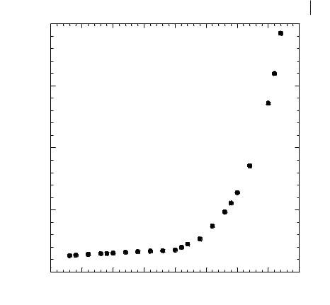
The haloaluminate ionic liquids are prepared by mixing two solids, an organic chloride and an aluminium halide (e.g., [EMIM]Cl and AlCl3). These two solids react to form ionic liquids with a single cation and a mix of anions, the anion composition depending strongly on the relative molar amounts of the two ingredients used in the preparation. The effect of anionic composition on the viscosity of haloaluminate ionic liquids has long been recognized. Figure 3.2-2 shows the absolute viscosities of the [EMIM]Cl/AlCl3 ionic liquids at 303 K over a range of compositions.
When the amount of [EMIM]Cl is below 50 mol %, the viscosity is relatively constant, only varying from 14 to 18 cP. However, when the [EMIM]Cl exceeds 50 mol %, the absolute viscosity begins to increase, eventually rising to over 190 cP at 67 mol % [EMIM]Cl [17]. This dramatic increase in viscosity is strongly correlated to the corresponding growth in chloride ion concentration as the [EMIM]Cl mol % increases, and appears to be the result of hydrogen bonding between the Cl– anions and the hydrogen atoms on the imidazolium cation ring [29–32].
The size of the cation in the chloroaluminate ionic liquids also appears to have an impact on the viscosity. For ionic liquids with the same anion(s) and compositions, the trend is for greater viscosity with larger cation size (Table 3.2-2). An additional contributing factor to the effect of the cation on viscosity is the asymmetry of the alkyl substitution. Highly asymmetric substitution has been identified as important for obtaining low viscosities [17].
The addition of co-solvents to ionic liquids can result in dramatic reductions in the viscosity without alteration of the cations or anions in the system. The haloaluminate ionic liquids present a challenge, due to the reactivity of the ionic liquid. Nonetheless, several compatible co-solvents including benzene, dichloromethane, and acetonitrile have been investigated [33–37]. The addition of as little as 5 wt. % acetonitrile or 15 wt. % benzene or methylene chloride was able to reduce the
Absolute Viscosity (cP)
3.2 Viscosity and Density of Ionic Liquids 65
200
150
100
50
0
30 |
35 |
40 |
45 |
50 |
55 |
60 |
65 |
70 |
Mol % EMIMCl
Figure 3.2-2: Change in the absolute viscosity (cP) as a function of the [EMIM]Cl mol % in an [EMIM]Cl/AlCl3 ionic liquid at 303 K.
absolute viscosity by 50 % for [EMIM]Cl/AlCl3 ionic liquids with less than 50 mol % AlCl3 [33]. Non-haloaluminate ionic liquids have also been studied with a range of co-solvents including water, toluene, and acetonitrile. The ionic liquid response is similar to that observed in the haloaluminate ionic liquids. The addition of as little as 20 mol % co-solvent reduced the viscosity of a [BMIM][BF4] melt by 50 % [28].
3.2.2
Density of Ionic Liquids
Densities are perhaps the most straightforwardly determined and unambiguous physical property of ionic liquids. Given a quality analytical balance and good volumetric glassware the density of an ionic liquid can be measured gravimetrically (i.e., the sample can be weighed).