

Professional Visual Studio 2005 (2006) [eng]
.pdf
Part IV
Security and Modeling
Chapter 14: Code Generation
Chapter 15: Security Concepts
Chapter 16: Cryptography
Chapter 17: Obfuscation


Code Generation
One of the core goals of Visual Studio 2005 is to reduce the amount of code that developers have to write. There are two ways that this can be done: either reduce the total amount of code that has to be written or reduce the amount that actually has to be written by developers. This chapter focuses on how Visual Studio 2005 generates code in order to reduce the amount of code that needs to be written. This in turn reduces the chances of error, while providing a much richer user interface through which to build your application.
This chapter looks in detail at the new Class Designer that comes with Visual Studio 2005 and explains how you can use it to design and refactor your class architecture. This chapter also examines other techniques for generating code within Visual Studio 2005.
Class Designer
The design process for an application typically involves at least a sketch of the classes that are going to be created and how they interact. Visual Studio 2005 provides a design surface, called the Class Designer, onto which classes can be drawn to form a class diagram. Fields, properties, and methods can then be added to the classes, and relationships can be established between classes. Although this design is called a class diagram, it supports classes, structures, enumeration, interfaces, abstract classes, and delegates.
Before you can start working with a class diagram, you need to add one to the project. This can be done by either adding a new class diagram to a project or by selecting the View Class Diagram menu item. A word of caution when using the second option to add a class diagram to a project: Using the View Class Diagram menu item will automatically add all the types defined within a project to the initial class diagram. Although this might be desirable, for a project that contains a large number of classes the process of creating and manipulating the diagram can be quite time consuming.
Chapter 14
Unlike some tools that require all types within a project to be on the same diagram, the class diagram can include as many or as few of your types as you want. This makes it possible to add multiple class diagrams to a single solution.
The Class Designer can be divided into four components: the design surface, the Toolbox, the Class Details window, and the property grid. Changes made to the class diagram are saved in a .cd file, which works in parallel with the class code files to generate the visual layout shown in the Class Designer.
Design Surface
The design surface of the Class Designer enables the developer to interact with types using a drag-and- drop style interface. Existing types can be added to the design surface by dragging them from either the class view or the Solution Explorer. If a file in the Solution Explorer contains more than one type, they are all added to the design surface.
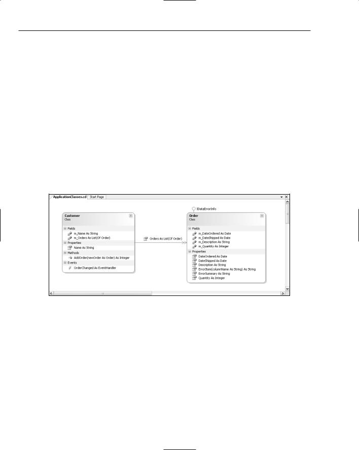
Figure 14-1 shows a simple class diagram that contains two classes: Customer and Order. Each class contains fields, properties, methods, and events. There is an association between the classes, as a Customer class contains a property called Orders that is a list of Order objects, and the Order class implements the IDataErrorInfo interface. All of this information is visible from this class diagram.
Figure 14-1
Each class appears as an entity on the class diagram, which can be dragged around the design surface and resized as required. A class is made up of fields, properties, methods, and events. In Figure 14-1, these components are grouped into compartments. Alternative layouts can be selected for the class diagram, which lists the components in alphabetical order or groups the components by accessibility.
The Class Designer is often used to view multiple classes to get an understanding of how they are associated. In this case, it is convenient to hide the components of a class to simplify the diagram. To hide all the components at once, use the toggle in the top-right corner of the class on the design surface. If only certain components need to be hidden they can be individually hidden, or the entire compartment can be hidden, by right-clicking on the appropriate element and selecting the Hide menu item.
180

Code Generation
Toolbox
To facilitate items being added to the class diagram there is a Class Designer tab in the Toolbox. To create an item, drag the item from the Toolbox onto the design surface or simply double-click it. Figure 14-2 shows the Toolbox with the Class Designer tab visible. The items in the Toolbox can be classified as either entities or connectors. Note the Comment item, which can be added to the Class Designer but does not appear in any of the code; it is there simply to aid documentation of the class diagram.
Figure 14-2
Entities
The entities that can be added to the class diagram all correspond to types in the .NET Framework. When a new entity is added to the design surface, it needs to be given a name. In addition, you need to indicate whether it should be added to a new file or an existing file.
Entities can be removed from the diagram by right-clicking and selecting the Remove From Diagram menu item. This will not remove the source code; it simply removes the entity from the diagram. In cases where it is desirable to delete the associated source code, select the Delete Code menu item.
The code associated with an entity can be viewed by either double-clicking on the entity or selecting View Code from the right-click context menu.
The following list explains each entity in the Toolbox:
Class: Fields, properties, methods, events, and constants can all be added to a class via the rightclick context menu or the Class Details window. Although a class can support nested types, they cannot be added using the Designer surface. Classes can also implement interfaces. In Figure 14-1, the Order class implements the IDataErrorInfo interface.
181

Chapter 14
Enum: An enumeration can only contain a list of members that can have a value assigned to them. Each member also has a summary and remark property, but these appear only as a comment against the member.
Interface: Interfaces define properties, methods, and events that a class must implement. Interfaces can also contain nested types, but recall that adding a nested type is not supported by the Designer.
Abstract Class: Abstract classes behave the same as classes except that they appear on the design surface with an italic name and are marked as MustInherit.
Structure: A structure is the only entity, other than a comment, that appears on the Designer in a rectangle. Similar to a class, a structure supports fields, properties, methods, events, and constants. It too can contain nested types. However, unlike a class, a structure cannot have a destructor.
Delegate: Although a delegate appears as an entity on the class diagram, it can’t contain nested types. The only components it can contain are parameters that define the delegate signature.
Module: A module can be used to group static methods. It can also contain nested types.
Connectors
Two types of relationships can be established between entities. These are illustrated on the class diagram using connectors, and are explained in the following list:
Inheritance: The inheritance connector is used to show the relationship between classes that inherit from each other.
Association: Where a class makes reference to another class, there is an association between the two classes. This is shown using the association connector. If that relationship is based around a collection — for example, a list of Order objects — this can be represented using a collection association. A collection association is shown in Figure 14-1 connecting the Customer and Order classes.
A class association can be represented as either a field or property of a class, or as an association link between the classes. The right-click context menu on either the field or property or the association can be used to toggle between the two representations.
Class Details
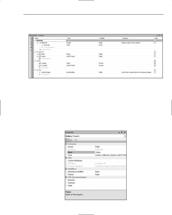
Components can be added to entities by right-clicking and selecting the appropriate component to add. Unfortunately, this is a time-consuming process and doesn’t afford you the ability to add method parameters or return values. New to Visual Studio 2005 is a Class Details window, which provides a user interface that enables components to be quickly entered. This window is illustrated in Figure 14-3 for the Customer class previously shown in Figure 14-1.
On the left side of the window are buttons that can aid in navigating classes that contain a large number of components. The top button can be used to add methods, properties, fields, or events to the class. The remaining buttons can be used to bring any of the component groups into focus. For example, the second button is used to navigate to the list of methods for the class. You can navigate between components in the list using the up and down arrow keys.
Because Figure 14-3 shows the details for a class, the main region of the window is divided into four alphabetical lists: Methods, Properties, Fields, and Events. Other entity types may have other components, such as Members and Parameters. Each row is divided into five columns that show the name, the return type, the modifier or accessibility of the component, a summary, and whether the item is hidden on the design
182
Code Generation
surface. In each case, the Summary field appears as an XML comment against the appropriate component. Events differ from the other components in that the Type column must be a delegate. You can navigate between columns using the left and right arrow keys, Tab (next column), and Shift+Tab (previous column).
Figure 14-3
Methods and properties can both take parameters. To enter parameters, use the right arrow key to expand the method node so that a parameter list appears. Selecting the Add Parameter node will add a new parameter to the method. Once added, the new parameter can be navigated to using the arrow keys.
Properties Window
Although the Class Details window is useful it does not provide all the information required for entity components. For example, properties can be marked as read-only, which is not displayed in the Class Details window. The Properties window in Figure 14-4 shows the full list of attributes for the Orders property of the Customer class.
Figure 14-4
183

Chapter 14
Figure 14-4 shows that the Orders property is read-only and that it is not shared. It also shows that this property is defined in the Customer.vb file. With the introduction of partial classes, a class may be separated over multiple files. When a partial class is selected, the File Name property will show all files defining that class as a comma-delimited list. As a result of an arbitrary decision made when implementing the Class Designer, some of these properties are read-only in the Designer. They can, of course, be adjusted within the appropriate code file.
Layout
As the class diagram is all about visualizing classes, you have several toolbar controls at your disposal to create the layout of the entities on the Designer. Figure 14-5 shows the toolbar that appears as part of the Designer surface.
Figure 14-5
The first three buttons control the layout of entity components. From left to right, the buttons are Group by Kind, Group by Access, and Sort Alphabetically.
The next two buttons are used to automate the process of arranging the entities on the design surface. On the left is the Layout Diagram button, which will automatically reposition the entities on the design surface. It will also minimize the entities, hiding all components. The right button, Adjust Shapes Width, adjusts the size of the entities so that all components are fully visible.
Entity components, such as fields, properties, and methods, can be hidden using the Hide Member button.
The display style of entity components can be adjusted using the next three buttons. The left button, Display Name, sets the display style to show only the name of the component. This can be extended to show both the name and the component type using the Display Name and Type button. The right button, Display Full Signature, sets the display style to be the full component signature. This is clearly the most useful, although it takes more space to display.
The remaining controls on the toolbar enable you to zoom in and out on the Class Designer, and to display the Class Details window.
Exporting
Quite often, the process of designing which classes will be part of the system architecture is a part of a much larger design or review process. Therefore, it is a common requirement to export the class diagram for inclusion in reports.
You can export a class diagram either by right-clicking the context menu from any space on the Class Designer or via the Class Diagram menu. Either way, selecting the Export Diagram as Image menu item opens a dialog prompting you to select an image format and filename for saving the diagram.
184
Code Generation
Other Code-Generation Techniques
Several other features within Visual Studio 2005 could be loosely classified as code-generation techniques, as they significantly reduce the code that you have to write. Because most of these are covered in more detail elsewhere in the book, this section can be used as a quick reference for those chapters.
Snippets
A large proportion of the code that developers have to write is mundane, such as writing property accessors for private member fields. You can often identify code blocks that you find yourself writing repeatedly. For these cases, you could have an electronic pin-board full of code snippets that you could include when you have to accomplish a particular task. Visual Studio 2005 ships with a large number of code snippets in all supported languages, and an editor has been built as a community project to create new snippets.
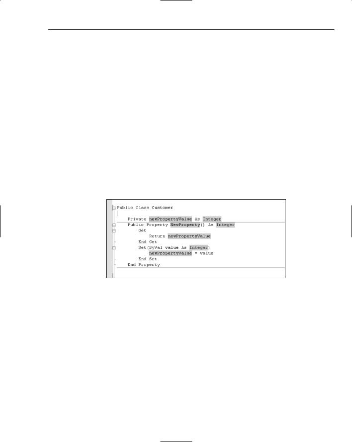
Figure 14-6 shows an example of a snippet being used to add a public property with an associated private backing field to the Customer class. The highlighted portions of the snippet (shown in green onscreen) indicate that sections should be replaced with custom values. In this case, three values need to be replaced: the name of the backing field, the type of the field and property, and the name of the property. Some developers choose to override this default snippet with their own snippet, which only requires two replacements. This can be done using the community-built Snippet Editor.
Figure 14-6
Snippets are covered in more detail in Chapter 19.
Refactoring
With a lot of emphasis being placed on agile development methodologies, refactoring is an important technique for reviewing and simplifying code. The premise is that the simpler the code, the easier it is to test and the less likely it is to contain bugs. Out of the box, only C# really supports refactoring. VB.NET has basic support for renaming methods but requires a third-party product to provide real refactoring support.
An example of the refactoring support provided in C# is the Preview Changes dialog, shown in Figure 14-7, which is displayed when renaming a method. When electing to rename a method using C# refactoring, all uses of this method are located and you are presented with this dialog to either accept or reject changes to all code paths that might be affected by the name change.
185