

15
The ITI Dental Implant System
Hans-Peter Weber, Daniel A. Buser, and Dieter Weingart
ridge augmentations involving bone grafts as described in detail in Chapter 17. From a mechanical view point, the standard diameter S implant is the strongest of the ITI family. To our knowledge, not one implant fracture has been reported worldwide to date.
The implant bed is prepared with three different spiral drills of increasing diameter (Figure 15.2).5 Confirmation of the sink depth, tapping of the screw thread, and placement of the implant are performed with the same instruments as are used for the HS implant. For the diameter-reduced screw, only the first two spiral drills, a diameter-reduced depth gauge, and a diameter-reduced tap are used.
Furthermore, a ratchet and a guidance key are necessary to screw thread the bone walls of the recipient site and to insert the implant. In implant sites with a normal or high bone density, the thread is cut in the entire length of the bone cavity prior to the insertion of the implant to avoid primary pressure peaks after placement of the implant. In implant sites with more spongy bone, the thread is cut only in the coronal portion of the cavity, and the implant is inserted in a self-tapping mode to achieve sufficient primary stability.7
Above the bone crest, the diameter of the smoothly machined implant neck flutes out to 4.8 mm to better match the diameter of a natural tooth. This allows for an emergence profile for aesthetic and functionally designed restorations. If necessary, the bone-sink depth of the implant can be varied by the surgeon during implant placement to enhance the aes-
The S implant is the successor of the TPS, or Swiss, screw.2 thetic aspect. The S implant is available in diameters of 4.1 mm (stan-
dard) and 3.3 mm (diameter reduced). Both types come in lengths (bone-sink depths) of 8 to 16 mm. Thread profile and head geometry are the same for both and are also identical to the HS implants later described.3–5 The screw threads improve the primary stability of the implant in its bony bed. Thus sufficient primary stability can also be achieved in implant sites with a spongy bone structure. Today, the fullbody screw is the most important ITI implant, and it is universally indicated in recipient sites with a vertical bone height of 10 mm or more. The S implant is also the implant of choice for maxillofacial surgical applications such as
138

15. The ITI Dental Implant System
FIGURE 15.1 The ITI dental implants from right to left: diameter reduced solid screw, standard diameter solid screw, hollow screw, hollow cylinder straight and angled.
The HS implant is available in sink depth of 8, 10, and 12 mm. The preparation of the bone cavity is carried out with the following instruments: three round burs of increasing diameters, a predrill, and a trephine mill (Figure 15.3).3–7 An internal irrigation system is available for the trephine mill to reduce the risk of bone-damaging temperatures. Extended experimental tests6 demonstrated that this cooling system allows the reduction of the temperature in the peri-implant bone structure during preparation, which is important for the avoidance of postoperative bone necrosis. In addition, the same instruments (tap, ratchet, guidance key) as for the standarddiameter full-body screw are used to cut the screw thread into the bone wall of the recipient site and to insert the implant. Regarding tapping implant sites of different bone quality and sink depth of the implant, the same principle is applied as for S implants.7
Hollow-Cylinder (HC) Implant
In its basic outline, the HC implant is the successor of the ITI type-F implant,1 which was first used clinically in 1979, gen-
139
FIGURE 15.3 Instruments for hollow screw site preparation.
erally for the treatment of edentulous mandibles and occasionally for single-tooth replacements or other indications.9,10 The modified HC implant was specifically developed for single-tooth replacements in the anterior maxilla.3,4 The HC implant is available both in a straight and an angled version (15° angulation in the neck portion). Both types are identical in their bone-anchoring section with an outer diameter of 3.5 mm. The angled HC implant is mainly used in indications with a maxillary anterior alveolar protrusion, a frequently found condition in that jaw region (Figure 15.4). HC implants are available in three different lengths of 8-, 10-, and 12-mm
FIGURE 15.2 Instruments for solid screw site preparation.
FIGURE 15.4 Use of angled hollow cylinder to correct the angulation between implant axis and crown, i.e., in sites with anterior alveolar protrusion.

140 |
H.-P. Weber, D.A. Buser, and D. Weingart |
FIGURE 15.5 Instruments for hollow cylinder site preparation.
sink depth. They are press-fit implants, which achieve the required primary stability with the preparation of a precise, congruent implant bed. The instruments necessary for bone preparation are in part the same as for the HS implant (Figure 15.5): three round burs of increasing diameters, predrill, trephine mill, and a color-coded depth gauge. However, tap, ratchet, and guidance key are not necessary. To insert the implant, the insertion device is attached to the implant top in the sterile ampoule. The implant is then removed from the ampoule and placed into the bone cavity until a slight resistance is detectable. Subsequently, the inserting device is removed, and the implant is tapped to its final position using a special tapping instrument and a mallet. The gentle press-fit after insertion allows for good primary stability in recipient sites with a firm bone structure.
ITI Implant Material and Tissue Reactions
ITI implants are endosseous implants that are anchored in the bone and penetrate the soft tissue cover. Therefore, the im-
FIGURE 15.6 Titanium-plasma-sprayed surface (TPS) in a close-up view.
plant surface is not only in contact with the bone but also with the mucosa.
Since their inception 20 years ago, ITI implants have been made of commercially pure titanium with a TPS surface in the bone-anchoring section. This coating procedure, first described by Hahn and Palich,11 was introduced in implant dentistry for the first time with ITI implants in 1974. It creates a rough and microporous implant surface, with a porosity between 30 and 50 m (Figure 15.6). The oxide film responsible for the biocompatibility of titanium forms on this sprayed layer. Therefore, the biocompatibility of the TPS surface is equivalent to a solid titanium body. Technical details of this procedure and the TPS surface were described by Steinemann.12
Bone
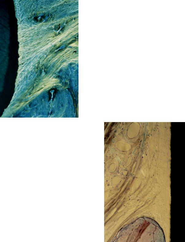
Direct bone apposition onto TPS surfaces was clearly shown at the beginning of the research project in animal experiments, and results were reported by Schroeder and coworkers in 1976 and 1978 using a new histologic technique with nondecalcified sections.13,14 This phenomenon of direct bone-implant contact is often termed osseointegration,15 or functional ankylosis.16 Light-microscopic images demonstrate the anchorage of titanium implants with osseointegration (Figure 15.7). The
FIGURE 15.7 Micrograph demonstrating direct bone-to-implant contact (osseointegration) to TPS surface (experimental sample from primate).

15. The ITI Dental Implant System
FIGURE 15.8 Direct bone-implant contact without interpositioning of soft tissue. Blood vessels in contact with implant surface (experimental sample from canine model).
higher magnification reveals the direct apposition of newly formed bone onto the surface of titanium implants with a TPS surface without an intervening layer of connective tissue. The vitality of the bone is demonstrated by the presence of osteocytes and blood vessels close to the implant surface (Figure 15.8). Osseointegration was also confirmed on a few human implants, which had to be removed (e.g., due to recurrent peri-implant infections in the crestal area; see Figure 15.9). Furthermore, direct bone-implant contact was also demonstrated in scanning electron-microscopic analyses, as well as in a transmission electron-microscopic study by Listgarten et al.17 using titanium evaporated epoxy resin implants (Figure 15.10). Osseointegration is generally not observed to have 100% bone contact along a given implant surface. The extent of bone-implant interface depends mainly on three factors: (1) the implant and surface material used; (2) the roughness of the implant surface; and (3) the density of the surrounding bone.
As mentioned earlier, ITI implants have been coated with a TPS surface since their inception in 1974 as this porous titanium surface offers several advantages from a clinical point of view. An animal study in rats demonstrates that the TPS surface accelerates bone apposition during early wound heal-
141
FIGURE 15.9 Osseointegration in apical section of hollow-cylinder implant, cross-sectional view (human explant).
ing.18 TPS implants revealed the first visible bone-implant contact after 7 days of healing, whereas smooth titanium implants demonstrated the first contacts after 21 days. In a study of miniature pigs, titanium implants with TPS coatings demon-
FIGURE 15.10 Direct bone apposition to TPS surface in electron microscopic view (magnification 16,000, sample from canine experiment with TPS coated epoxy implants).
142 |
H.-P. Weber, D.A. Buser, and D. Weingart |
Supracrestal Connective Tissue
and Epithelium
Dental implants are not covered by a closed integument. The fact that they penetrate the mucosa and are consequently exposed to the environment of the oral cavity with all its possible contaminants creates a delicate problem. Thus the components of the soft tissue cover (i.e., the supracrestal connective tissue as well as the epithelium) have to act as an important barrier between the internal and external environment if long-term function is to be expected.26
As demonstrated above, bone as mineralized connective tissue adheres to the rough TPS surface. Therefore, it could be expected that a similar reaction would occur when the nonmineralized supracrestal connective tissue directly contacted the TPS surface, and when the implant post is located in keratinized attached mucosa. Light-microscopic experiments on TPS-coated implants placed in monkeys16 or beagle dogs28 demonstrated a fiber orientation perpendicular to the implant surface (Figure 15.11). However, studies in beagle dogs evaluating titanium implants with smooth or sandblasted surfaces17,29 revealed no evidence of perpendicular fiber attach-
FIGURE 15.11 Supracrestal connective tissue fibers in perpendicular orientation to TPS coated implant surface (cross-sectional view).
strated a significantly higher percentage of direct bone-implant contact in cancellous bone when compared to smoothor finestructured titanium surfaces.19 And finally, a study in sheep revealed significantly higher removal torques for TPS implants when compared with smoothor fine-structured titanium implants.20 Summarizing these studies, it can be concluded that titanium implants with TPS surfaces achieve significantly faster and better bone anchorage when compared with titanium implants with smoothor fine-structured surfaces.
To achieve osseointegration of ITI implants, four prerequisites need to be fulfilled: (1) biocompatible material; (2) atraumatic surgical technique using a slow drilling technique to prevent overheating of the bone; (3) primary implant stability; and (4) a healing period of 3 to 4 months without direct loading.7 As already mentioned, ITI implants were designed as nonsubmerged implants. If placed as such, they are not covered by the oral mucosa during healing and penetrate the crestal mucosa from the time of implant placement. In contrast to the frequently stated requirement for a submerged implant placement,15 nonsubmerged ITI implants achieve osseointegration with high predictability if the aforementioned prerequisites are followed.7,21–25 This clinical fact observed over more than 20 years has been confirmed in the recent past by several experimental stud-
ies.13,14,16,17,19,26–30
FIGURE 15.12 Absence of perpendicular fibers close to the implant surface. Collagen fibers with a parallel orientation distant from the implant surface. Blood vessel and cell-free zone in contact with implant surface.

15. The ITI Dental Implant System |
143 |
epithelium-like and, more apically, junctional epithelium-like cell layers along the implant surface; see Figure 15.15).
Prosthodontic Concept
Abutments
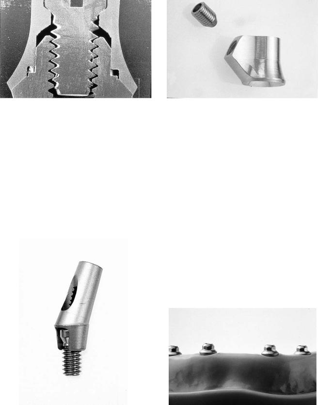
Various abutments are available for the two-part ITI implants. They consist of a number of conical abutments for screwretained and/or cemented restorations including an angled abutment (Figure 15.16), an octagonal abutment for screwretained restorations only, and the retentive anchor used for implant treatments with overdentures. The abutments all have the same apical portion fitting to the inner top portion of the implant with an M2 (2-mm) screw and an 8° cone (Figure 15.17). This cone-to-screw interface serves as a nonrotational friction fit or mechanical lock on the basis of the Morse taper principle. It has shown to be three to four times as strong as a conventional, flat-coupling screw connection.31 To secure the abutments into this nonrotational fit, they are inserted with a torque of 35 Ncm using a special torque instrument (Figure 15.18).
FIGURE 15.13 Circular fibers around implant post in cross-sectional view (canine experiment).
ment to the tested nonporous titanium surfaces. The connective tissue in direct contact with the implant post was mainly dominated by circularly oriented collagen fibers. This inner zone of connective tissue was free of blood vessels and resembled most likely an inflammation-free scar-tissue formation (Figure 15.12). The obvious difference to the aforementioned studies with perpendicular fiber attachment can probably be explained by the difference in the surface characteristics.
Based on biological considerations for successful maintenance of healthy peri-implant soft tissues, ITI implants have a smoothly machined titanium surface in the transmucosal section to reduce the risk of plaque accumulation. Thus it has to be expected that a similar arrangement of circularly oriented connective tissue fibers is predominantly present around ITI implants in patients due to the smooth surface in the supracrestal area (Figure 15.13).
Different light-microscopic studies using nonsubmerged titanium implants in different animal models16,28–30 demonstrated no evidence of an epithelial downgrowth to the bonecrest level. The micrographs revealed the formation of a peri-implant sulcus, with the most apical epithelial cells being located approximately 1 mm above the bone-crest level (Figure 15.14). The epithelial structures around titanium implants are similar to those found around teeth (i.e., sulcular
FIGURE 15.14 Microradiograph demonstrating peri-implant soft tissue morphology. At the top apical extension of peri-implant epithelium. At the bottom is the crestal bone height. Connective tissue contact height extends from the crestal bone height to the epithelium.

144 |
H.-P. Weber, D.A. Buser, and D. Weingart |
FIGURE 15.15 Peri-implant epithelium resembling sulcular and junctional epithelium at natural teeth.
FIGURE 15.16 ITI abutments. From left to right: Solid abutments, angled abutment retentive anchor, and octa-abutment.
FIGURE 15.17 Cone-to-screw design (Morse taper principle) for rotation safe anchorage of abutment in implant.
FIGURE 15.18 Torque instrument for abutment insertion (35 Ncm) and tightening of occlusal screws (20 Ncm).
FIGURE 15.19 Solid conical abutments (4-mm, 5.5-mm, and 7-mm height) for cemented restorations.

15. The ITI Dental Implant System
Cemented Restorative Technique
FIGURE 15.20 Schematic overview of restorative steps for cemented restorations.
Conical Abutments
The conical abutments come as solid abutments without internal screw threads in heights of 4, 5.5, and 7 mm, for cementation of restorations (Figure 15.19). They are especially easy to use and, therefore, save time and reduce costs. After placement of the conical abutment, an impression is made, a stone cast is poured, and the crowns or fixed partial dentures are waxed directly to the stone model and then completed as conventional crown-bridge work (Figure 15.20).
145
Non-Repositionable
Transfer Technique
a
b
FIGURE 15.22 (a,b) Schematic overview of procedural steps for screw-retained restorations with the octa-abutment concept and its prefabricated components.
Octa-abutment for Screw-Retained Restorations
For screw-retained prostheses, the Octa-system with different prefabricated parts for accurate transfer and laboratory procedures has been added to the ITI armamentarium in the more recent past.31 The top of the Octa-abutment has eight sides and is 1.5 mm high (Figure 15.21), with an M2 screw hole in its top to retain the restoration. This 2-mm occlusal screw limits the occurrences of screw loosening or fractures commonly reported for implant restorations. The Octa-abutment is anchored in the implant with the same cone-to-screw interface as the con-
FIGURE 15.21 Octa-abutment for screw-retained restoration in closeup view.
ical abutments described earlier, and they provide a nonrotational friction fit. Transfer copings are used for impressions. Once an impression is made, one-piece analogs are secured into the transfer copings and die stone poured. After the stone has set, the transfer copings are removed. Prefabricated gold copings made from nonoxidizing, high gold-content alloys with a high melting range are placed on the analogs. Long wax-up or guide screws are used to secure the copings on the analogs and to create the space for the future occlusal screw access canal. The frame of the future restoration is then waxed and cast to the copings. In case of porcelain-fused-to-gold restorations, the porcelain is added thereafter. It is important that for such restorations, a layer of gold compatible with the ceramic material to be used is cast onto the copings. Gold copings with an octagonal inside are chosen for single-tooth cases, whereas gold copings with rounded insides are used for fixed partial dentures. The step-by-step procedure for screw-retained restorations is summarized in Figure 15.22a,b. The prefabricated gold copings have an outstanding precision, which can be documented in SEM images (Figure 15.23). The resistance of the implant- abutment-superstructure complex to lateral forces is superior due to the precise component fit and even enhanced by the 45° inclination of the implant shoulder. Angled abutments and a transversal screw retention concept have been added to the prosthodontic concept more recently. For instructions on their use, the reader is referred to the respective, detailed system literature. They assist the restorative dentist in overcoming im-
146
FIGURE 15.23 Precise fit of gold coping to 45° implant shoulder.
plant angulation and/or divergence problems (Figures 15.24 and 15.25).
Overdentures on Bars
In cases in which support for dentures is needed, two to four implants can be placed and restored with a gold bar and an overdenture after completion of implant healing.9,10 Prefabricated gold copings, gold bars with round or oval profile, and gold clips or bar sleeves are the available components. Note that these gold copings are different from the ones used for
H.-P. Weber, D.A. Buser, and D. Weingart
FIGURE 15.25 Transverse screw coping for single-tooth restorations.
cast restorations. The bar-retaining copings are only to be used to affix prefabricated bar segments via soldering procedure, in that they are fit tightly onto the bars and fitted into the denture as retentive elements (Figures 15.26–15.28).
Overdenture on Retentive Anchors
When moderate additional retention is required for a mandibular or maxillary denture, two implants can be placed, and round (retentive) anchors are inserted in the implants after the 3- to 4-month healing period.32 Because no reopening surgery is necessary, the restorative phase begins at the end of this healing period. Female matrices are processed into the denture to fit tightly to the retentive anchors with a simple impression and pick-up method (Figures 15.29–15.31).
Case Reports
Figures 15.32 to 15.37 show illustrative examples from case reports.
FIGURE 15.24 Angled abutments to correct angulation problems in |
FIGURE 15.26 Octa-abutments on four implants for bar-retained over- |
fixed partial denture cases. |
denture. |

15. The ITI Dental Implant System |
147 |
FIGURE 15.27 Gold bar in place. Bar segments are soldered to gold copings different from the ones used for cast restorations.
FIGURE 15.28 Finished overdenture demonstrating bar clips in situ. A metal lingual plate for strength and minimizing interference with tongue function is recommended as shown.
FIGURE 15.30 Schematic illustration of function of gold matrix on retentive anchor. The presence of the polyethylene sleeve around the matrix is important for proper retentive function of the matrix.
FIGURE 15.29 Retentive anchor in close-up view.
FIGURE 15.31 Tissue side of overdenture with retentive matrices in place.
148 |
H.-P. Weber, D.A. Buser, and D. Weingart |
a |
b |
c |
d |
e
FIGURE 15.32 (a) Master cast with dies of conical abutments for cemented crowns. (b) Finished restorations on dies. (c) Lingual view of cemented restorations. (d) Buccal view of cemented resotrations.
(e) Radiographic control 3 years after implant placement.

15. The ITI Dental Implant System |
149 |
a |
b |
c |
d |
FIGURE 15.33 (a) Custom-angled abutment in case with maxillary alveolar protrusion in right canine area. Note the placement of the implant below tissue level for aesthetic crown emergence.
(b) View of custom angled abutment on an HS implant. The custom angled abutment was waxed and cast on an octogonal gold coping and then custom milled. (c) Procelain-fused-to-metal crown in place. (d) Radiographic control at 3 years after crown insertion.

150 |
H.-P. Weber, D.A. Buser, and D. Weingart |
a |
c |
b
FIGURE 15.34 (a) Octa-abutment placed for screw-retained restoration in area of the right canine. Note again the deeper implant placement for aesthetic purposes. (b) Final restoration in place. (c) Radiographic control 2 years after insertion.
15. The ITI Dental Implant System |
151 |
a |
b |
c |
d |
e
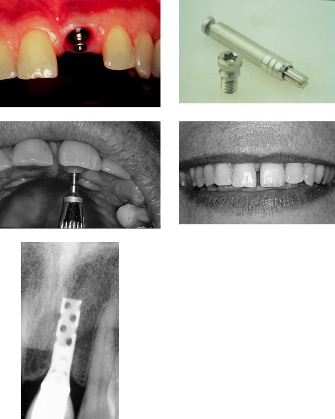
FIGURE 15.35 (a) Crown post inserted in octa-abutment for fixation of crown via transversal screw in area of missing upper left central incisor. (b) Close-up view of crown post and SCS screwdriver. (c) Fixation of crown with transversal screw. (d) Aesthetic appearance of completed tooth replacement. (e) Radiographic control 2 years after crown insertion.

152 |
H.-P. Weber, D.A. Buser, and D. Weingart |
a |
b |
c |
d |
e |
f |
FIGURE 15.36 (a) Octa-abutments on four implants placed in maxillary edentulous patient. (b) High-profile milled bar in situ. (c) Palatefree overdenture with bilateral custom fabricated locks which can be
easily opened and closed by the patient. (d) Close-up view of one of the locks. (e) Frontal view of final prosthesis. (f) Radiographic control at 1 year.

15. The ITI Dental Implant System |
153 |
a |
b |
c |
d |
FIGURE 15.37 (a) Retentive anchors in place. (b) Radiographic control at 4 years. (c) Retentive anchor matrices processed in lower overdenture. (d) Frontal view of final prostheses (i.e., lower overdenture, upper complete denture).
References
1.Sutter F, Schroeder A, Straumann F. ITI Hohlzylinder Systeme.
Prinzipien Methodik Swiss Dent. 1983;4:21.
2.Babbush CA, Kent JN, Misiek DJ. Titanium plasma-sprayed (TPS) screw implants for the reconstruction of the edentulous mandible. J Oral Maxillofac Surg. 1986;44:274.
3.Sutter F, Schroeder A, Buser D. The new concept of ITI hollow cylinder and hollow screw implants. Part I: Engineering and design. Int J Oral Maxillofac Implants. 1988;3:161.
4.Buser D, Schroeder A, Sutter F, Lang NP. The new concept of ITI hollow-cylinder and hollow-screw implants: Part 2, Clinical aspects, indications, and early clinical results. Int J Oral Maxillofac Implants. 1988;3:173.
5.Sutter F, Schroeder A, Buser D. Das neue ITI-Implantatkonzept. Technische Aspekte und Methodik. Quintessenz. 1988;39: (Teil 1)1875–XX; (Teil 2)2057.
6.Sutter F, Krekeler G, Schwammberger AE, Sutter FJ. Das ITIBonefitimplantatsystem: Implantatbettgestaltung. Quintessenz. 1991;42:541.
7.Buser D, Weber HP, Brägger U. The treatment of partially endentulous patients with ITI hollow-screw implants: Pre-surgical evaluation and surgical procedures. Int J Oral Maxillofac Implants. 1990;5:165.
8.Sutter F. Raveh J. Titanium-coated hollow screw and reconstruction plate system for bridging of lower jaw defects: Biomechanical aspects. Int J Oral Maxillofac Surg. 1988;17:267.
9.Schroeder A, Maeglin B, Sutter F. Das ITI-Hohlzylinderim- plantat Typ-F zur Prothesenretention beim zahnlosen Kiefer.
Scheiz Monatsschr Zahnheilk. 1983;93:720.
10.ten Bruggenkate CM, Muller K, Oosterbeek HS. Clinical evaluation of the ITI (F-type) hollow cylinder implant. Oral Surg Oral Med Oral Pathol. 1990;70:693.
11.Hahn H, Palich W. Preliminary evaluation of porous metal surfaced titanium for orthopedic implants. J Biomed Mater Res. 1970;4:571.
12.Steinemann S. The properties of titanium. In: Schroeder A, Sutter F, Krekeler G, eds. Oral Implantology: Basics-ITI Hollow Cylinder. New York: Thieme Medical Publishers; 1991:37–58.
13.Schroeder A, Pohler O, Sutter F. Gewebsreaktion auf ein TitanHohlzylinderimplantat mit Titan-Spritzschichtoberfläche. Schweiz Monatsschr Zahnheilk. 1976;86:713.
14.Schroeder A, Stich H, Straumann F, Sutter F. Über die Anlagerung von Osteozement an einen belasteten Implantatkörper.
Schweiz Monatsschr Zahnheilk. 1978;88:1051.
15.Brånemark PI, Hansson BO, Adell R, et al. Osseointegrated implants in the treatment of the edentulous jaw. Experience from a 10-year period. Scand J Plast Reconstruct Surg II. (suppl 16), 1977.
154
16.Schroeder A, van der Zypen E, Stich H, Sutter F. The reactions of bone, connective tissue and epithelium to endosteal implants with titanium-sprayed surfaces. J Maxillofac Surg. 1981;9:15.
17.Listgarten MA, Buser D, Steinemann S, Donath K, Lang NP, Weber HP. Light and transmission electron microscopy of the intact interface between bone, gingiva and non-submerged titaniumcoated epoxy resin implants. J. Dent Res. 1992;71:364–371.
18.Kirsch A, Donath K. Tierexperimentelle Untersuchungen zur Bedeutung der Mikromorphologie von Titanimplantatoberflächen. Fortschr Zahnärztl Implantol. 1984;1:35.
19.Buser D, Schenk RK, Steinemann S, Fiorellini JP, Fox C, Stich H. Influence of surface characteristics on bone reactions to titanium implants: a histomorphometric study in miniature pigs.
J Biomed Mater Res. 1991;25:889.
20.Wilke HJ, Claes L, Steinemann S. The influence of various titanium surfaces on the interface shear strength between implants and bone. Adv Biomater. 1990;9:309.
21.Buser D, Weber HP, Lang NP. Tissue integration of non-sub- merged implants. Clin Oral Implants Res. 1990;1:33.
22.Buser D, Weber HP, Brägger U, Balsiger C. Tissue integration of one-stage ITI implants: 3-year results of a longitudinal study with hollow-cylinder and hollow-screw implants. Int J Oral Maxillofac Implants. 1991;6:405.
23.Buser D, Sutter F, Weber HP, Belser U, Schroeder A. The ITI Dental Implant System: basics, indications, clinical procedures and results. Clark’s Clin Dentistry. 1992;5:1–22.
24.Mericske-Stern R. Clinical evaluation of overdenture restorations supported by osseointegrated implants: a retrospective study. Int J Oral Maxillofac Implants. 1990;5:375.
H.-P. Weber, D.A. Buser, and D. Weingart
25.Mericske-Stern R, Steinlin-Schaffner T, Marti P, Geering AH. Peri-implant mucosal aspects of ITI implants supporting overdentures. A five-year longitudinal study. Clin Oral Implants Res. 1994;5:9–18.
26.McKinney R, Steflik DE, Koth DL. Per, peri, or trans? A concept from improved dental terminology. J Prosthet Dent. 1984; 52:267.
27.Gotfredsen K, Rostrup E, Hjøerting-Hansen E, Stoltze K, BudtzJørgensen E. Histological and histomorphometrical evaluation of tissue reactions to endosteal implants in monkeys. Clin Oral Implants Res. 1991;2:30.
28.Buser D, Stich H, Krekeler G, Schroeder A. Faserstrukturen der periimplantären Mukosa bei Titan-Implantaten. Eine tierexperimentelle Studie am Beagle-Hund Z Zahnärztl Implantol. 1989;
5:15.
29, Buser D, Weber HP, Donath K, et al. Soft tissue reactions to non-submerged unloaded titanium implants in beagle dogs.
J Periodontol. 1992;63:225.
30.Weber HP, Buser D, Donath K, Fiorellini JP, Doppalapudi V, Paquette DW, et al. Comparison of healed tissues adjacent to submerged and non-submerged unloaded titanium dental implants. A histologic and histometric study in beagle dogs. Clin Oral Implants Res. 1996;7:11.
31.Sutter F, Weber HP, Sorensen J, Belser U. The new restorative concept of the ITI Dental Implant System: engineering and design. Int J Periodont Rest Dent. 1993;13:408.
32.Mericske-Stern R, Geering AH. Implantate in der Totalprothetik: Die Verankerung der Totalprothese im zahnlosen Unterkiefer durch zwei Implantate mit Einzelattachment. Schweiz Monatsschr Zahnmed. 1988;98:871.