


GPS NAVIGATION
5.2 NAVIGATION MAP (MFD)
NAVIGATION MAP PAGE
This section describes the MFD Navigation Map Page setup and operation which in most cases will be a “onetime” operation since the setup can be customized to accommodate the individual needs of the pilot.
Figure 5-1 Navigation Map Page (not all map display items shown)
The Navigation Map Page (Figure 5-1) is the first page in the Map Page Group and provides the following GPS Navigation display capability:
•Map display showing airports, NAVAIDs, airspaces, land data (highways, cities, lakes, rivers, borders, etc.) with names
•Map pointer information (distance and bearing to pointer,locationofpointer,name,andotherpertinent information)
•Map range
•Wind direction and speed
•Heading indication
•Aircraft icon representing present position
•Icons for enabled map features
•Track vector
•Topography scale
•Fuel range ring
•Topography data
•Airways
5-2 |
Garmin G1000 Pilot’s Guide for Cessna Nav III |
190-00498-02 Rev.A |

GPS NAVIGATION
NAVIGATION MAP SETUP
 NOTE: Refer to the appendices for a description of map symbols.
 NOTE: MFD Navigation Map operations involving the display of traffic, terrain, and weather data are described in the Hazard Awareness Section.
Navigation Map setup (which in most cases is a “one-time” operation) customizes display information to accommodate the individual needs of the pilot and flight plan. The map can be customized using the map setup option listed in the Navigation Map Page Menu (Figure 5-2; displayed by pressing the MENU Key with the Navigation Map Page displayed).
Navigation Map Page
Menu
Map Setup
Option
Figure 5-2 Navigation Map Page Menu
To display the map setup group (Figure 5-3), press the ENT Key with ‘Map Setup’ highlighted. The following options are displayed:
•Map
•Weather (refer to the Hazard Awareness Section)
•Traffic (refer to the Hazard Awareness Section)
•Aviation
•Airways
•Land
Setup
Groups
Figure 5-3 Map Setup Group
190-00498-02 Rev.A |
Garmin G1000 Pilot’s Guide for Cessna Nav III |
5-3 |

GPS NAVIGATION
MAP GROUP
Figure 5-4 Map Group
Orientation
There are four map orientation selections: North up, Track up, DTK up, and HDG up. The orientation default setting is ‘North Up’.
•North up fixes the top of the map to a north heading.
•Track up adjusts the top of the map display to the current ground track.
•Desired Track Up (DTK up) fixes the top of the map display to the desired course.
•Heading Up (HDG up) fixes the top of the map display to the current aircraft heading.
Changing the map orientation:
1)With the Navigation Map Page displayed, press the MENU Key. The cursor flashes on the ‘Map Setup’ option.
2)Press the ENT Key. The Map Setup Menu is displayed.
3)Select the ‘ORIENTATION’ field. Select the desired orientation and press the ENT Key.
4)Press the FMS Knob to return to the Navigation Map Page.
5-4 |
Garmin G1000 Pilot’s Guide for Cessna Nav III |
190-00498-02 Rev.A |

GPS NAVIGATION
Auto Zoom
Necessary Conditions
Auto zoom occurs on all pages on which the following conditions exist:
•Auto zoom is enabled on the system
•No terrain alert condition (caution or warning) exists on the page
•No traffic advisory exists on the page
•A valid waypoint is active by means of an activated direct-to navigation (including OBS mode), or an activated leg of a loaded flight plan
•The aircraft is in the air
•The map orientation is north up, heading up, track up, or desired track up
Override Conditions
•In the event of a terrain alert condition (caution or warning), the map field of a page allowing auto zoom and displaying TAWS/TERRAIN data automatically adjusts to the lowest map range in which the highest priority alert is clearly visible and proceeds to auto zoom when the terrain alert condition clears.
•In the event of a new traffic advisory alert, the map field of a page allowing auto zoom and capable of displaying traffic advisory alerts automatically adjusts to the lowest map range in which the traffic advisory is clearly visible and proceeds to auto zoom when the traffic advisory clears.
•Auto zoom is overridden by a manual adjustment of the range knob while on any page allowing auto zoom and remain overridden on all pages allowing auto zoom until at least one of the following conditions occurs:
•A new waypoint becomes active
•The aircraft transitions from on ground to in air
•The time since the last manual adjustment of the range knob exceeds the non-zero
auto zoom time out value.
• A terrain alert condition occurs or new traffic advisory alert occurs.
Auto Zoom Time Settings
The minimum and maximum look forward times (configurable per airframe and on the Map Setup page for the ‘Map’ group) determines the minimum and maximum radial distances to display from the current aircraft position when in north up orientation or from the map center when in heading up, desired track up, or track up orientations based upon the aircraft’s ground speed.
•The maximum look forward time is the basis for which the maximum zoom range necessary to display the active waypoint, if possible, is determined.
•The minimum look forward time is the basis for which the minimum zoom range necessary to display the active waypoint, if possible, is determined.
190-00498-02 Rev.A |
Garmin G1000 Pilot’s Guide for Cessna Nav III |
5-5 |

GPS NAVIGATION
•The time out time (configurable on the Map Setup page for the “Map” group) determines the amount of time that auto zoom is allowed to be overridden by a manual adjustment of the range knob unless the time out value is zero, in which case the override condition never times out.
Final Flight Plan Waypoints
The map adjusts to display any ranges between and including the maximum look forward time (as describedbelowfor“OtherWaypoints”)andadefaultminimummaprangeof1.5nmor3km(depending on system units) when the active waypoint is valid, the final waypoint in the flight plan, and is an airport or airport runway waypoint. If a direct-to waypoint outside of the active flight plan is activated the new active waypoint is considered as the final waypoint in the flight plan.
Missed Approach Point Waypoints
The map adjusts to display any ranges between and including a default maximum map range of 2000 nm or 4000 km (depending on system units) and a default minimum map range of 1.5 nm or 3 km (depending on system units) when the active waypoint is valid and is the missed approach point waypoint.
Other Waypoints
The zoom range is determined based upon the following minimum and maximum look forward time combinations when the active waypoint is a valid waypoint other than the final flight plan waypoint or the missed approach point waypoint:
•When the maximum look forward time is greater than the minimum look forward time settings, the map adjusts to display any zoom ranges between and including the maximum look forward time and the minimum look forward time.
•When the maximum look forward time is equivalent to the minimum look forward time setting, the map adjusts to display the minimum look forward time.
•When the maximum look forward time is set to zero, the map adjusts to display any zoom ranges between and including a default maximum map range of 2000 nm or 4000 km (depending on system units) and the minimum look forward time.
•When the minimum look forward time is set to zero, the map adjusts to display any zoom ranges between and including the maximum look forward time and a default minimum map range of 1.5 nm or 3 km (depending on system units).
When both the minimum and maximum look forward times are set to zero, the map adjusts to display between and including a default maximum map range of 2000 nm or 4000 km (depending on system units) and a default minimum map range of 1.5 nm or 3 km (depending on system units). A non-zero maximum look forward time setting less than the minimum look forward time setting is prevented.
Zoom Range Transitions - Auto Zoom In
The map zooms in as long as the following conditions are true:
•The active waypoint is visible on the map in a lower zoom range or the current zoom range exceeds the maximum zoom range.
•The current zoom range exceeds the minimum zoom range.
5-6 |
Garmin G1000 Pilot’s Guide for Cessna Nav III |
190-00498-02 Rev.A |

GPS NAVIGATION
Auto Zoom Out
The map zooms out as long as the following conditions are true:
•The active waypoint is not visible in the current zoom range or the current zoom range is below the minimum zoom range.
•The current zoom range does not exceed the maximum zoom range
Enabling/disabling automatic zoom:
1)Press the MENU Key with the Navigation Map Page displayed. The cursor flashes on the ‘Map Setup’ option.
2)Press the ENT Key. The Map Setup Menu is displayed.
3)Select the ‘Map’ group
4)Press the ENT Key.
5)Highlight the ‘AUTO ZOOM’ field.
6)Select ‘Off’,‘MFD Only’,‘PFD Only’, or ‘ALL On’.
7)Press the ENT Key to accept the selected option. The flashing cursor highlights the ‘MAX LOOK FWD’ field. Times are from zero to 999 minutes.
8)Use the small and large FMS Knobs to set the time. Press the ENT Key.
9)Repeat step 8 for ‘MIN LOOK FWD’ (zero-99 minutes) and ‘MAX LOOK FWD’ (zero to 999 minutes).
10)Press the FMS Knob to return to the Navigation Map Page.
190-00498-02 Rev.A |
Garmin G1000 Pilot’s Guide for Cessna Nav III |
5-7 |

GPS NAVIGATION
Land Data
The Navigation Map can display background land data (roads, lakes, borders, etc). The background land data can also be removed from the display (turned off).
Enabling/disabling land data:
1)Press the MENU Key with the Navigation Map Page displayed. The cursor flashes on the ‘Map Setup’ option.
2)Press the ENT Key. The Map Setup Menu is displayed.
3)Select the ‘Map’ group.
4)Press the ENT Key.
5)Highlight the ‘LAND DATA’ field.
6)Select ‘On’ or ‘Off.’.
7)Press the FMS Knob to return to the Navigation Map Page.
Track Vector
Track Vector
Figure 5-5 Track Vector
The Navigation Map can display a track vector as a dashed light blue line segment with an arrowhead attached to the end, extended to a predicted location in 60 seconds along the current aircraft track (Figure 5-5). The track vector is useful in minimizing track angle error. The track vector look-ahead times are selectable times (30 sec, 60 sec, 2 min, 5 min, 10 min, 20 min) that determine the length of the track vector to project from the current aircraft position so that the arrow head is constantly pointing to the location that the aircraft will be along the current aircraft track in the selected time.
For example, if a user selects the 60 second track vector look-ahead time on the Map Setup page, the track vector displayed on the map is the length equivalent to 60 seconds from the current aircraft position along the current aircraft track.
5-8 |
Garmin G1000 Pilot’s Guide for Cessna Nav III |
190-00498-02 Rev.A |

GPS NAVIGATION
Enabling/disabling the track vector:
1)Press the MENU Key with the Navigation Map Page displayed. The cursor flashes on the ‘Map Setup’ option.
2)Press the ENT Key. The Map Setup Menu is displayed.
3)Select the ‘Map’ group.
4)Press the ENT Key.
5)Highlight the ‘TRACK VECTOR’ field.
6)Select ‘On’ or ‘Off’. Press the ENT Key to accept the selected option. The flashing cursor highlights the ‘LOOK AHEAD’ time field. Use the FMS Knobs to select the desired time (30 seconds, 60 seconds, 2 minutes, 5 minutes, 10 minutes, 20 minutes). Press the ENT Key.
7)Press the FMS Knob to return to the Navigation Map Page.
Wind Vector
The wind vector is displayed in the upper right corner of the map and displays wind direction and speed (in knots). Wind direction is indicated by an arrow.
Enabling/disabling the wind vector:
1)Press the MENU Key with the Navigation Map Page displayed. The cursor flashes on the ‘Map Setup’ option.
2)Press the ENT Key. The Map Setup Menu is displayed.
3)Select the ‘Map’ group.
4)Press the ENT Key.
5)Highlight the ‘WIND VECTOR’ field.
6)Select ‘On’ or ‘Off’.
7)Press the FMS Knob to return to the Navigation Map Page.
190-00498-02 Rev.A |
Garmin G1000 Pilot’s Guide for Cessna Nav III |
5-9 |
GPS NAVIGATION
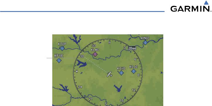
Nav Range Ring
Track Vector
Figure 5-6 NAV Range Ring
The Nav Range Ring (Figure 5-6) shows the direction of travel (ground track) on a rotating compass card. The range of the Nav Ring is determined by the map range: 125 feet (500 feet map range) to 500 nm (2000 nm map range).
Enabling/disabling the Nav Range Ring:
1)Press the MENU Key with the Navigation Map Page displayed. The cursor flashes on the ‘Map Setup’ option.
2)Press the ENT Key. The Map Setup Menu is displayed.
3)Select the ‘Map’ group.
4)Press the ENT Key.
5)Highlight the ‘NAV RANGE RING’ field.
6)Select ‘On’ or ‘Off’.
7)Press the FMS Knob to return to the Navigation Map Page.
Topo Data
Topographic data can be enabled or disabled on the Navigation Map using the ‘TOPO DATA’ setting. The topo data range is the maximum map range on which topo data is displayed.
Enabling/disabling topo data and select a topo data range:
1)Press the MENU Key with the Navigation Map Page displayed. The cursor flashes on the ‘Map Setup’ option.
2)Press the ENT Key. The Map Setup Menu is displayed.
3)Select the ‘Map’ group.
4)Press the ENT Key.
5)Highlight the ‘TOPO DATA’ field.
5-10 |
Garmin G1000 Pilot’s Guide for Cessna Nav III |
190-00498-02 Rev.A |
GPS NAVIGATION
6)Select ‘On’ or ‘Off’.
7)Highlight the range field. TOPO ranges are from Off to 2000 nm.
8)To change the TOPO range setting, turn the small FMS Knob to display the range list.
9)Select the desired range.
10)Press the ENT Key.
Topo Scale
The topo scale setting enables or disables the topography range box located in the lower right corner of the Navigation Map.
Enabling/disabling the topo range box:
1)Press the MENU Key with the Navigation Map Page displayed. The cursor flashes on the ‘Map Setup’ option.
2)Press the ENT Key. The Map Setup Menu is displayed.
3)Select the ‘Map’ group and press the ENT Key.
4)Highlight the ‘TOPO Range’ field.
5)Select ‘On’ or ‘Off’.
6)Press the FMS Knob to return to the Navigation Map Page.
Terrain Data
Terrain data can be enabled or disabled on the Navigation Map Page using the ‘TERRAIN DATA’ setting. A data range can also be selected. The data range is the maximum map range that terrain data is displayed.
Enabling/disabling terrain data and to select a terrain data range:
1)With the Navigation Map Page displayed, press the MENU Key to display the Navigation Map Page Menu. The cursor flashes on the ‘Map Setup’ option.
2)Press the ENT Key. The Map Setup Menu is displayed.
3)Select the ‘Map’ group.
4)Press the ENT Key.
5)Highlight the ‘TERRAIN DATA’ field.
6)Select ‘On’ or ‘Off’.
7)Press the ENT Key to accept the selected option. The flashing cursor highlights the range field. TERRAIN ranges are from Off to 2000 nm.
8)To change the TERRAIN range setting, turn the small FMS Knob to display the range list.
9)Select the desired range.
10)Press the ENT Key. Press the FMS Knob to return to the Navigation Map Page.
190-00498-02 Rev.A |
Garmin G1000 Pilot’s Guide for Cessna Nav III |
5-11 |

GPS NAVIGATION
Obstacle Data
Obstacles
Figure 5-7 Obstacle Data
Obstacle data can be enabled or disabled on the Navigation Map Page using the ‘OBSTACLE DATA’ setting. A data range can also be selected. The data range is the maximum map range that terrain data is displayed.
Enabling/disabling obstacle data and to select a terrain data range:
1)With the Navigation Map Page displayed, press the MENU Key to display the Navigation Map Page Menu. The cursor flashes on the ‘Map Setup’ option.
2)Press the ENT Key. The Map Setup Menu is displayed.
3)Select the ‘Map’ group.
4)Press the ENT Key.
5)Highlight the ‘OBSTACLE DATA’ field.
6)Select ‘On’ or ‘Off’.
7)Press the ENT Key to accept the selected option. The flashing cursor highlights the range field. OBSTACLE ranges are from Off to 50 nm.
8)To change the OBSTACLE range setting, turn the small FMS Knob to display the range list.
9)Select the desired range.
10)Press the ENT Key.
11)Press the FMS Knob to return to the Navigation Map Page.
5-12 |
Garmin G1000 Pilot’s Guide for Cessna Nav III |
190-00498-02 Rev.A |

GPS NAVIGATION
Fuel Range Ring (Fuel RNG) (RSV)
The map can display a fuel range ring which shows the flight distance that the aircraft has remaining. A dashed green circle indicates the transition range to reserve fuel. A solid green circle indicates the range of all fuel, including the reserve fuel. If only reserve fuel remains, the range is indicated by a solid yellow circle.
Enabling/disabling the fuel range ring and select a fuel range time:
1)Press the MENU Key with the Navigation Map Page displayed. The cursor flashes on the ‘Map Setup’ option.
2)Press the ENT Key. The Map Setup Menu is displayed.
3)Select the ‘Map’ group.
4)Press the ENT Key.
5)Highlight the ‘FUEL RNG (RSV)’ field.
6)Select ‘On’ or ‘Off’.
7)Highlight the fuel reserve time field. The time indicated is the time the aircraft can fly with remaining fuel on board.
8)To change the reserve fuel time, enter a time (00:00 to 23:59; hours:minutes). The default setting is 00:45 minutes.
9)Press the ENT Key.
10)Press the FMS Knob to return to the Navigation Map Page.
WEATHER GROUP
Refer to the Hazard Awareness Section for information pertaining to the setup and display of the Weather Group Options.
TRAFFIC GROUP
Refer to the Hazard Awareness Section for information pertaining to the setup and display of the Traffic Group Options.
190-00498-02 Rev.A |
Garmin G1000 Pilot’s Guide for Cessna Nav III |
5-13 |

GPS NAVIGATION
AVIATION GROUP
Figure 5-8 Aviation Group
•Active Flight Plan (ACTIVE FPL)- The active flight plan zoom range sets the maximum range at which the active flight plan magenta line is shown on the display (off - 2000 nm).
•Active Flight Plan Waypoint (ACTIVE FPL WPT)- The active flight plan waypoint label size sets the size at which the active flight plan names appear on the display (none, small, medium, and large). The zoom range sets the maximum range at which active flight plan waypoints appear on the display (off - 2000 nm).
•Large, Medium, and Small Airports (LARGE APT, MEDIUM APT, SMALL APT) - The airport label size sets the size at which the large, medium, or small airport names size appear on the display. The zoom range sets the maximum range at which the airports appear on the display:
•Large: off - 500 nm
•Medium: off - 300 nm
•Small: off - 100 nm
•Safe Taxi (SAFETAXI) - The zoom range sets the maximum range at which taxiways appear on the display:
•Off - 20 nm
•Runway Extension (RWY EXTENSION) - The zoom range sets the maximum range at which runway extensions appear on the display:
•Off - 100 nm
5-14 |
Garmin G1000 Pilot’s Guide for Cessna Nav III |
190-00498-02 Rev.A |

GPS NAVIGATION
•Intersection, Non-Directional Beacon, and VOR Waypoints (INT WAYPOINT, NDB WAYPOINT, VOR WAYPOINT) - The INT, NDB, and VOR label size sets the maximum range at which the NAVAIDS names appear on the display. The zoom range sets the maximum range at which the NAVAIDS appear on the display:
•INT: off - 30 nm
•NDB: off - 30 nm
•VOR: off - 300 nm
•Airspace Boundaries (CLASS B/TMA, CLASS C/TCA, and CLASS D) - The airspace zoom range sets the maximum range at which the three classes of airspace appear on the display. The zoom range sets the maximum range at which the airspace boundaries appear on the display:
•CLASS B: off - 500 nm
•CLASS C: off - 500 nm
•CLASS D: off - 300 nm
•“Other” Airspace Boundaries (RESTRICTED, MOA (Military), OTHER AIRSPACE, and TFR (temporary flight restrictions). The other airspace boundary zoom range sets the maximum range at which restricted, MOA, and other (training, caution, danger, warning, and alert areas) airspace boundaries are displayed
•RESTRICTED: off - 500 nm
•MOA (MILITARY): off - 500 nm
•OTHER/ADIZ: off - 500 nm
•TFR: (only present when GDL 69 is installed): off - 2000 nm
Selecting an aviation group item text size:
1)Press the MENU Key with the Navigation Map Page displayed. The cursor flashes on the ‘Map Setup’ option.
2)Press the ENT Key. The Map Setup Menu is displayed.
3)Select the ‘Aviation’ group.
4)Press the ENT Key. The cursor flashes on the ‘ACTIVE FPL’ field.
5)Select the desired aviation option.
6)Select the desired text size.
7)Press the ENT Key to accept the selected text size.
8)Press the FMS Knob to return to the Navigation Map Page.
Selecting an aviation group item range:
1)Press the MENU Key with the Navigation Map Page displayed. The cursor flashes on the ‘Map Setup’ option.
2)Press the ENT Key. The Map Setup Menu is displayed.
3)Select the ‘Aviation’ group.
4)Press the ENT Key. The cursor flashes on the ‘ACTIVE FPL’ field.
190-00498-02 Rev.A |
Garmin G1000 Pilot’s Guide for Cessna Nav III |
5-15 |

GPS NAVIGATION
5)Select the desired aviation option.
6)Select the desired range (RNG). Press the ENT Key to accept the selected option.
7)Press the FMS Knob to return to the Navigation Map Page.
AIRWAYS GROUP
Figure 5-9 Airways Setup Options
The Airways group manages the display of airways. See the airways section for more information on using the airways feature.
•Airways - Selects the display of airways:
•OFF (default setting)
•ALL
•LO Only (200 nm default setting)
•HI Only (300 nm default setting)
•LOW ALT AIRWAY - The range sets the maximum range at which low altitude airways appear on the display.
•LO ALT AIRWAY: 500 ft. - 500 nm
•HI ALT AIRWAY - The range sets the maximum range at which high altitude airways appear on the display.
•HI ALT AIRWAY: 500 ft. - 500 nm
5-16 |
Garmin G1000 Pilot’s Guide for Cessna Nav III |
190-00498-02 Rev.A |

GPS NAVIGATION
Airway Line Style
The route of low altitude airways are drawn in gray (the same shade used for roads). Note that VFR sectional charts use light blue for low altitude airways – but on the G1000, that color has the potential to be confused with airspace boundaries.
Hi Altitude
Airways
Figure 5-10 High Altitude Airways
The route of high altitude airways are drawn in green. This color is used on Jeppesen charts where high altitude airways are shown on low altitude charts. When both types of airways are selected for display at the same time, high altitude airways will be drawn on top of low altitude airways.
Low
Altitude
Hi Altitude Airways
Airways
Figure 5-11 High and Low Altitude Airways
Note that the shade of green used for high altitude airways is darker than any shade used to render topographical detail such that it should stand out even when TOPO is selected.
190-00498-02 Rev.A |
Garmin G1000 Pilot’s Guide for Cessna Nav III |
5-17 |

GPS NAVIGATION
Airways which are classified in the database as all altitude routes will be drawn as high altitude routes whenever both route types are selected for display at the same time. Otherwise, these routes will be drawn in the style (low or high) that has been selected for display. The line drawn for an airway leg that terminates at a VOR ends where the line intersects with the VOR Compass Rose unless there is an adjacent waypoint on the airway that is drawn inside the compass rose. Lines drawn for airway legs that terminate at other symbol types (NDBs or Intersections) end at a point that leaves a small gap between the line end point and the symbol.
Airway Waypoint Symbols
When airways are drawn on the map, the symbols needed to show the airway waypoints (VORs, NDBs and Intersections) are also drawn regardless of the map setting that would otherwise control the drawing of that symbol. Labels (Identifiers) for VORs, NDBs and Intersections used on airways will always be drawn according to the map settings for those items. For example, if airways are enabled to be drawn at the 200 nm range setting, Intersection symbols will be drawn as needed to depict the airway even though Intersections are enabled for display only for range settings of 30 nm or less. The intersection identifiers will be shown for range settings up to 30 nm. Only the intersection symbols will be shown for range settings greater than 30 nm. When airways are drawn on the MAP, all airway “optional” waypoints are drawn.
Airway Labels
Airway labels are light gray rectangles with black text (colors will be similar to that used for national highway labels) and are centered on the airway line. When several airways follow a common waypoint sequence, the common sequence has multiple labels placed as close together as practical with only the label border overlapping. To reduce clutter, some airways may not be labeled.
5-18 |
Garmin G1000 Pilot’s Guide for Cessna Nav III |
190-00498-02 Rev.A |

GPS NAVIGATION
LAND GROUP
Figure 5-12 Land Group
•Latitude/Longitude (LAT/LON) - The LAT/LON label size sets the size at which latitude/longitude labels appear on the display (none, small, medium, and large). The zoom range sets the maximum range at which LAT/LON waypoints appear on the display (off - 2000 nm).
•Highways, Roads, and Railroads (FREEWAY, LOCAL HWY, LOCAL ROAD, RAILROAD) - The highway and road zoom range sets the maximum range at which highways, roads, and railroads appear on the display:
•FREEWAY: off - 800 nm
•NATIONAL HWY: off - 80 nm
•LOCAL HWY: off - 30 nm
•LOCAL ROAD: off - 15 nm
•RAILROAD: off - 30 nm
•Cities and Towns (LARGE CITY, MEDIUM CITY, SMALL CITY) - The cities and town label size sets the maximum range at which city and town names appear on the display. The zoom range sets the maximum range at which cities and towns appear on the display:
•LARGE CITY (approximate populations greater than 200,000): off - 1500 nm
•MEDIUM CITY (approximate populations greater than 50,000): off - 200 nm
•SMALL CITY (approximate populations greater than 5,000): off - 50 nm
190-00498-02 Rev.A |
Garmin G1000 Pilot’s Guide for Cessna Nav III |
5-19 |

GPS NAVIGATION
• States and Provinces, Rivers and Lakes, and User Waypoints (STATE/PROV, RIVER/LAKE, USER WAYPOINT) - the label range sets the maximum range at which the three categories appear on the display. The zoom range sets the maximum range at which the three categories appear on the display:
•STATE/PROV: off - 1500 nm
•RIVER/LAKE off - 500 nm
•USER WAYPOINT: off - 300 nm
Selecting a land group item text size:
1)Press the MENU Key with the Navigation Map Page displayed. The cursor flashes on the ‘Map Setup’ option.
2)Press the ENT Key. The Map Setup Menu is displayed.
3)Select the ‘Land’ group.
4)Press the ENT Key. The cursor flashes on the ‘LAT/LON’ field.
5)Select the desired land option.
6)Select the desired text size.
7)Press the ENT Key to accept the selected option.
8)Press the FMS Knob to return to the Navigation Map Page.
Selecting a land group item range:
1)Press the MENU Key with the Navigation Map Page displayed. The cursor flashes on the ‘Map Setup’ option.
2)Press the ENT Key. The Map Setup Menu is displayed.
3)Select the ‘Land’ group.
4)Press the ENT Key. The cursor flashes on the ‘LAT/LON’ field.
5)Select the desired land option.
6)Press the ENT Key to accept the selected option.
7)Press the FMS Knob to return to the Navigation Map Page.
5-20 |
Garmin G1000 Pilot’s Guide for Cessna Nav III |
190-00498-02 Rev.A |
GPS NAVIGATION
NAVIGATION MAP OPERATIONS
SELECTING A MAP RANGE
Map Range Indicator
Figure 5-13 Map Range Indicator
The Navigation Map’s range has 28 different settings, from 500 feet to 2000 nm. The current range is indicated in the lower right corner of the Navigation Map Page and represents the top-to-bottom distance covered by the map. To change the map range turn the Joystick counter-clockwise to zoom in ( -, decreasing), or clockwise to zoom out (+, increasing).
190-00498-02 Rev.A |
Garmin G1000 Pilot’s Guide for Cessna Nav III |
5-21 |

GPS NAVIGATION
DECLUTTERING THE MAP
The declutter feature allows the pilot to progressively step through 4 levels of removing map information. The declutter level is displayed in the DCLTR Softkey and next to the Declutter Menu Option. Table 5-1 lists the features that are turned off at each declutter level. In Table 5-1, the shaded area under the declutter level headings represent map items “removed” and the white areas represent map items “displayed” for the various levels of declutter.
 NOTE: Automatic map decluttering takes place during an instrument approach.
Decluttering the map:
1) Press the MENU Key with the Navigation Map Page displayed.
3)Select ‘Declutter’. The current declutter level is shown.
4)Press the ENT Key.
OR:
Press the DCLTR Key with the Navigation Map Page displayed. The current declutter level is shown. With each press, another level of map information is removed.
Declutter Option
Figure 5-14 Map Declutter Option
5-22 |
Garmin G1000 Pilot’s Guide for Cessna Nav III |
190-00498-02 Rev.A |

GPS NAVIGATION
No Declutter |
Declutter-1 Declutter-2 Declutter-3 |
Flight Plan Route Lines
Flight Plan Route Waypoints
Rivers/Lakes
Topography Data
Terrain Proximity Data
Map Borders
Bearing Line
Stormscope Lightning Strike Data
NEXRAD
XM Lightning Data
Traffic
Airports
Runway Labels
Restricted
MOA (Military)
User Waypoints
Latitude/Longitude Grid
VORs
NDBs
Intersections
Class B/TMA
Class C/TCA
Class D
Other/ADIZ
Obstacles
Land/Country Text
Cities
Roads
Railroads
Major Political Boundaries
River/Lake Names
Table 5-1 Map Declutter Levels
190-00498-02 Rev.A |
Garmin G1000 Pilot’s Guide for Cessna Nav III |
5-23 |

GPS NAVIGATION
MAP PANNING
Map Data
Map
Selection
Figure 5-15 Map Panning
Map panning (Figure 5-15) moves the map beyond its current limits without adjusting the map range. When the panning function is selected by pressing the Joystick, the map pointer flashes on the map display. A window also appears at the top of the map display showing the latitude/longitude position of the arrow, the bearing and distance to the pointer from the aircraft’s present position, and the elevation of the land at the position of the arrow. When the map arrow crosses an airspace boundary, the boundary is highlighted and airspace information is shown at the top of the display. The information includes the name and class of airspace, the ceiling in feet expressed in Mean Seal Level (MSL), and the floor in feet MSL.
Panning the map:
1)Press the Joystick to display the map arrow.
2)Move the Joystick in the general direction of the desired destination to place the arrow at the destination location. When the arrow is placed on an object,the name of the object is highlighted (even if the name was not originallydisplayedonthemap). Thisfeatureappliestoeverythingdisplayedonthemapexceptroutelines.When any map feature or object is selected on the map display,features or objects are displayed in the window located at the top of the display. From here,the pilot can designate the waypoint as the direct-to destination. When the arrow crosses an airspace boundary, the boundary is highlighted and airspace information is displayed at the top of the display.
3)Press the Joystick to remove the Map Pointer and recenter the map on the aircraft’s current position.
5-24 |
Garmin G1000 Pilot’s Guide for Cessna Nav III |
190-00498-02 Rev.A |

GPS NAVIGATION
Creating user waypoints from the Navigation Map Page:
1)With the Navigation Map Page displayed, press the Joystick to activate the panning function. The Map Pointer is displayed at the present aircraft position.
2)After placing the map arrow at the desired position, press the ENT Key. The User Waypoint Information Page is displayed with the captured position.
3)Enter a waypoint name.
4)Press the ENT Key to accept the selected name. The first reference waypoint field is highlighted.
5)If desired, enter the identifier of the reference waypoint and the radial and distance to the reference waypoint.
6)Press the ENT Key to accept.
7)Press the FMS Knob to remove the flashing cursor.
DISPLAYING TOPOGRAPHIC DATA ON THE MAP
Maximum elevation of topography presently displayed on-
screen Minimum elevation of
topography presently displayed on-screen
Range of |
|
|
|
|
|
Aircraft altitude |
|
|
|
|
|
||
|
|
|
|
|
|
|
topography elevation |
|
|
|
Ground elevation |
||
|
|
|||||
presently displayed |
|
|
|
at present aircraft |
||
on-screen |
|
|
|
position |
||
Figure 5-16 Topography Scale
The Navigation Map displays various shades of topography land colors representing the rise and fall of land elevation, similar to aviation sectional charts (Figure 5-16). The Navigation Map can display a topographic range representing various key points of terrain elevation colors with their associated elevation values labeled.
Displaying topographic data on the Navigation Map:
1)Press the MAP Softkey.
2)Press the TOPO Softkey. Topographic data can also be displayed on the Navigation Map by using the ‘On/Off’ topo data map setup feature. See the Navigation Map Page Setup Menu Section for more information.
190-00498-02 Rev.A |
Garmin G1000 Pilot’s Guide for Cessna Nav III |
5-25 |

GPS NAVIGATION
3)Press the TOPOSoftkey again to remove topo data from the Navigation Map.When topographic data is removed from the page, the Jeppesen Nav data is presented on a black background.
NAVIGATION STATUS BOX
Table 5-17 GPS Navigation Status Box
The Navigation Status Box (Figure 5-17) is displayed in the top center of the MFD and PFD. The MFD contains four user-configurable fields which can display the information listed below. Instructions on changing a data field are given in the System Overview Section.
• Bearing to next waypoint (BRG) |
• Maximum Safe Altitude (MSA) |
• Distance to next waypoint (DIS) |
• True Airspeed (TAS) |
• Desired track to next waypoint (DTK) |
• Track angle error (TKE) |
• Enroute safe altitude (ESA) |
• Track angle (TRK) |
• Estimated Time of Arrival (ETA) |
• Vertical speed required (VSR) |
• Estimated Time Enroute (ETE) |
• Cross track error (XTK) |
• Ground Speed (GS) |
|
MEASURING BEARING AND DISTANCE |
|
Map Data
Reference
Point
Figure 5-18 Measuring Bearing and Distance
5-26 |
Garmin G1000 Pilot’s Guide for Cessna Nav III |
190-00498-02 Rev.A |

GPS NAVIGATION
The‘MeasureBearing/Distance’menuoptionprovidesaquickandeasymethodfordeterminingthebearing and distance between any two points on the Navigation Map. Pressing the ENT Key at the location selected with Measure Pointer allows bearing and distance from the newly selected reference to be acquired.
Figure 5-19 Measure Bearing/Distance Option
Measuring bearing and distance between any two points:
1)Press the MENU Key (with the Navigation Map Page displayed).
2)Highlight the ‘Measure Bearing/Distance’ field.
3)Press the ENT Key. A Measure Pointer is displayed on the map at the aircraft’s present position.
4)Move the Joystick to place the reference pointer at the desired location. The bearing and distance are displayed at the top of the map. Elevation at the current pointer position is also displayed. Pressing the ENT Key changes the starting point for measuring.
5)To exit the Measure Bearing/Distance option, press in the Joystick or select ‘Stop Measuring’ from the page menu.
6)Press the ENT Key.
Displaying Charts
ChartView and FliteCharts resemble the paper version of Jeppesen and NACO terminal procedures charts. The charts are displayed in full color with high-resolution. See the Additional Features section for more information on ChartView and FliteCharts.
Figure 5-20 ‘Show Chart’ Option
190-00498-02 Rev.A |
Garmin G1000 Pilot’s Guide for Cessna Nav III |
5-27 |