

- •Section 1 System Overview
- •1.1 System Description
- •1.2 Line Replaceable Units (LRU)
- •1.3 G1000 Controls
- •PFD/MFD Controls
- •Audio Panel Controls
- •1.4 Secure Digital (SD) Cards
- •1.5 System Power-up
- •1.6 System Operation
- •Normal Display Operation
- •Reversionary Display Operation
- •AHRS Operation
- •G1000 System Annunciations
- •Softkey Function
- •GPS Receiver Operation
- •1.7 Accessing G1000 Functionality
- •Menus
- •MFD Page Groups
- •MFD System Pages
- •Electronic Checklists (Optional)
- •1.8 Display Backlighting
- •Automatic Adjustment
- •Manual Adjustment
- •Section 2 flight Instruments
- •2.1 Flight Instruments
- •Airspeed Indicator
- •Attitude Indicator
- •Altimeter
- •Vertical Speed Indicator (VSI)
- •Vertical Deviation, Glideslope, & Glidepath Indicators
- •Horizontal Situation Indicator (HSI)
- •Course Deviation Indicator (CDI)
- •2.2 Supplemental Flight Data
- •Generic Timer
- •Outside Air Temperature
- •Wind Data
- •System Time
- •Vertical Navigation (VNV) Indications
- •2.3 PFD Annunciations and Alerting Functions
- •System Alerting
- •Traffic Annunciation
- •TAWS Annunciations
- •Low Altitude Annunciation
- •Altitude Alerting
- •Minimum Descent Altitude/Decision Height Alerting
- •Marker Beacon Annunciations
- •2.4 Abnormal Operations
- •Abnormal GPS Conditions
- •Unusual Attitudes
- •Section 3 Engine Indication System (EIS)
- •3.1 Engine Display
- •3.2 Lean Display
- •3.3 System Display
- •Section 4 audio panel and CNS
- •4.1 Overview
- •PFD/MFD Controls and Frequency Display
- •Audio Panel Controls
- •4.2 COM Operation
- •COM Transceiver Selection and Activation
- •COM Transceiver Manual Tuning
- •Quick-Tuning and Activating 121.500 MHz
- •Auto-tuning the COM Frequency
- •Frequency Spacing
- •Automatic Squelch
- •Volume
- •4.3 NAV Operation
- •NAV Radio Selection and Activation
- •NAV Receiver Manual Tuning
- •Auto-tuning the NAV Frequency
- •Marker Beacon Receiver
- •DME Tuning (Optional)
- •4.4 GTX 33 Mode S Transponder
- •Transponder Controls
- •Transponder Mode Selection
- •Entering a Transponder Code
- •IDENT Function
- •Flight ID Reporting
- •4.5 Additional Audio Panel Functions
- •Power-Up
- •Mono/Stereo Headsets
- •Speaker
- •Intercom
- •Clearance Recorder and Player
- •Entertainment Inputs
- •4.6 Audio Panel Preflight Procedure
- •4.7 Abnormal Operation
- •Stuck Microphone
- •COM Tuning Failure
- •Audio Panel Fail-Safe Operation
- •Reversionary Mode
- •Section 5 GPS Navigation
- •5.1 Introduction
- •5.2 Navigation Map (MFD)
- •Navigation Map Page
- •5.3 PFD Inset Map and Windows
- •Inset Map
- •PFD Windows
- •5.4 Direct-to-Navigation (MFD)
- •Selecting a Direct-to Waypoint
- •Clearing Vertical Constraints
- •Specifying a Course to a Waypoint
- •Canceling Direct-to Navigation
- •Direct-to Navigation Shortcuts
- •5.5 Direct-to-Navigation (PFD)
- •5.6 Airport Information (MFD)
- •Duplicate Waypoints
- •Additional Airport Runway Information
- •5.7 Intersection Information (MFD)
- •5.8 NDB Information (MFD)
- •5.9 VOR Information (MFD)
- •5.10 User Waypoint Information (MFD)
- •5.11 Nearest Airports (MFD)
- •5.12 Nearest Intersections (MFD)
- •5.13 Nearest NDB (MFD)
- •5.14 Nearest VOR (MFD)
- •5.15 Nearest User Waypoint (MFD)
- •5.16 Nearest Airspaces
- •5.17 Nearest Airports (PFD)
- •5.18 Flight Planning (MFD)
- •Airways/Jetways
- •Display of Airways on the Flight Plan Page
- •Vertical Navigation (VNV)
- •Navigating an Example Flight Plan
- •Parallel Track (PTK)
- •5.19 Flight Planning (PFD)
- •Operations
- •5.20 Procedures (MFD)
- •Leg Types Supported by the G1000
- •5.21 Procedures (PFD)
- •Operations
- •5.22 ABNORMAL OPERATION
- •Dead Reckoning
- •Section 6 Hazard Avoidance
- •6.1 XM Satellite Weather (Service Optional)
- •Activating XM Satellite Services
- •Using XM SATELLITE Weather Products
- •Weather Softkeys on the Weather Data Link Page
- •Setting Up the Weather Data Link Page
- •XM Satellite Weather on the Navigation Map
- •6.2 WX-500 Stormscope (Optional)
- •Setting Up Stormscope on the Navigation Map
- •Selecting the Stormscope Page
- •6.3 Terrain Proximity
- •Requirements
- •GPS Position and GPS-MSL Altitude
- •Displaying Terrain Proximity Data
- •Terrain Proximity Symbols
- •Terrain Proximity Page
- •Navigation Map Page
- •6.4 TAWS (Optional)
- •Requirements
- •TAWS Alerting
- •Using TAWS
- •TAWS Symbols
- •TAWS Alerts
- •6.5 Traffic
- •Traffic Information Service (TIS)
- •Honeywell KTA 870 TAS System (Optional)
- •ADS-B Traffic (Optional)
- •Section 7 Automatic Flight Control System
- •7.1 AFCS Controls
- •7.2 Flight Director Operation
- •Command Bars
- •Activating the Flight Director
- •7.3 Flight Director Modes
- •Pitch Modes
- •Roll Modes
- •7.4 Autopilot Operation
- •Engaging the Autopilot
- •Control Wheel Steering
- •Disengaging the Autopilot
- •7.5 Example Procedures
- •Departure
- •Intercepting a VOR Radial
- •Flying a Flight Plan/GPS Course
- •Descent
- •Approach
- •Go Around/Missed Approach
- •7.6 AFCS Annunciations and Alerts
- •AFCS Status Alerts
- •Overspeed Protection
- •Section 8 Additional Features
- •8.1 SafeTaxi
- •SafeTaxi Cycle Number and Revision
- •8.2 ChartView
- •ChartView Softkeys
- •Terminal Procedures Charts
- •Chart Options
- •Day/Night View
- •ChartView Cycle Number and Expiration Date
- •8.3 FliteCharts
- •FliteCharts Softkeys
- •Terminal Procedures Charts
- •Chart Options
- •Day/Night View
- •FliteCharts Cycle Number and Expiration Date
- •8.4 XM Radio Entertainment (Optional)
- •XM Satellite Radio Service
- •XM Service Activation
- •Using XM Radio
- •Automatic Audio Muting
- •8.5 Abnormal Operation
- •Annunciations and Alerts
- •Alert Level Definitions
- •NAV III Aircraft Alerts
- •CO Guardian Messages
- •G1000 System Annunciations
- •Other G1000 Aural Alerts
- •G1000 System Message Advisories
- •AFCS Alerts
- •TAWS ALERTS
- •TAWS System Status Annunciations
- •SD Card Use
- •Jeppesen Databases
- •Garmin Databases
- •Glossary
- •Frequently Asked Questions
- •General TIS Information
- •Introduction
- •TIS vs. TAS/TCAS
- •TIS Limitations
- •Map Symbols
- •Index
GPS NAVIGATION
VERTICAL NAVIGATION (VNV)
 NOTE: Refer to the Appendices for VNV Flight Planning definitions, abbreviations, and acronyms.
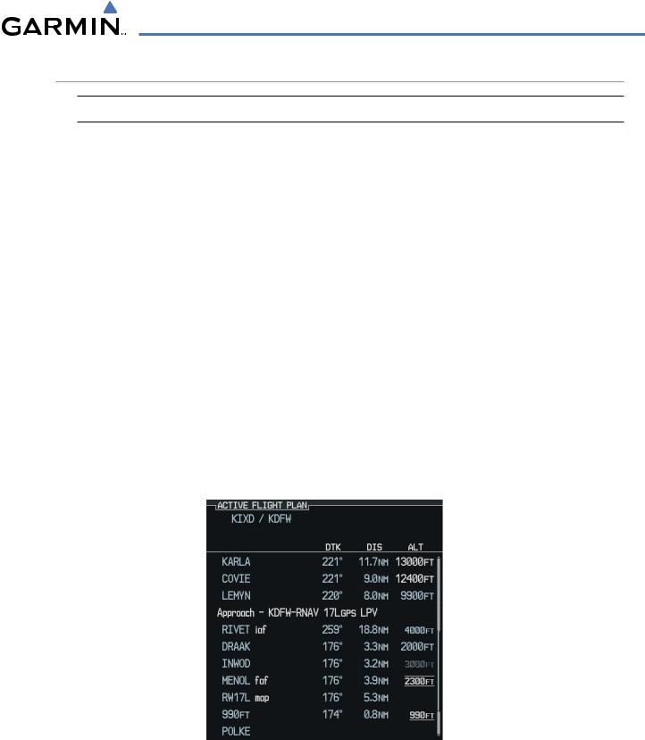
The G1000 System can use altitude constraints associated with lateral waypoints to give guidance for vertical navigation. These altitudes are, depending on the specific instance, entered by the pilot or retrieved from the published altitudes in the navigation database.
The navigation database only contains altitudes for procedures that call for “Cross at” altitudes. If the procedure states “Expect to cross at,” then the altitude will not be in the database. In this case the altitude may be entered manually.
When activating or loading an arrival or approach procedure into an active flight plan, the VNV ‘ALT’ fields will be populated with any altitudes that can be retrieved from the navigation database.
To help interpret the meanings of how the altitudes are presented, keep the following points in mind:
•When the altitude is displayed in light blue, the system is using that altitude to determine vertical speed and deviation guidance.
•When the altitude is displayed in white, it is not being used by the system to determine the vertical speed and deviation guidance.
•An altitude displayed as small text is an altitude that is published in the navigation database.
•Altitudes displayed as a light blue halftone cannot be used in the current vertical navigation calculations.
Refer to Figure 5-81 and Table 5-2 for more detail regarding the significance of text size and color.
|
|
|
|
|
|
Large |
|
|
|
|
|
|
|
|
|
White Text |
||||
|
|
|
|
|
Large Light |
|
|
|
|
||||
|
|
|
|
|
|
Blue Text |
|
|
|
|
Small Light |
||
|
|
|
|
|||
|
|
|
|
|
Blue Text |
|
|
|
|
|
|
Small Light Blue |
|
|
|
|
|
|
||
|
|
|
|
|
|
HalftoneText |
|
|
|
|
|
Small White |
|
|
|
|
|
|
||
|
|
|
|
|
|
Text with |
Figure 5-81 VNV Altitudes |
|
|
|
|
Altitude |
|
Restriction Bar |
||||||
190-00498-02 Rev.A |
Garmin G1000 Pilot’s Guide for Cessna Nav III |
5-89 |

GPS NAVIGATION
|
White Text |
Light Blue Text |
Light Blue Halftone Text |
|
|
|
|
|
|
|
Altitude calculated by the |
Altitude has been entered by the |
|
|
|
system estimating the altitude of |
|
||
|
pilot. Altitude is being used by |
|
||
|
the aircraft as it passes over the |
the system for vertical speed and |
The system cannot use this |
|
Large Text |
navigation point. This altitude |
deviation guidance. Altitude does |
altitude in determining vertical |
|
|
is provided as a reference and |
not match the published altitude |
speed and deviation guidance. |
|
|
is not being used by the system |
|||
|
in navigation database or no |
|
||
|
to determine vertical speed and |
|
||
|
published altitude exists. |
|
||
|
deviation guidance. |
|
|
|
|
Altitude is not being used to |
Altitude is being used by the |
|
|
|
system for vertical speed and |
|
||
|
determine vertical speed and |
|
||
|
deviation guidance. Altitude |
|
||
|
deviation guidance. Altitude |
The system cannot use this |
||
|
has been retrieved from the |
|||
Small Text |
has been retrieved from the |
altitude in determining vertical |
||
navigation database or has been |
||||
|
navigation database and is |
speed and deviation guidance. |
||
|
entered by the pilot and matches |
|||
|
provided as a reference. |
|
||
|
a published altitude in the |
|
||
|
|
|
||
|
|
navigation database. |
|
|
|
|
|
|
|
|
Table 5-2 VNV Altitude Text Size and Color |
|
||
Some altitudes retrieved from the database have associated restrictions indicating to stay ‘At’, ‘At or Above’, or ‘At or Below’ a specific altitude. These restrictions are indicated using a ‘bar’ above and/or below the appropriate altitude as shown in Figure 5-82.
 Stay AT or ABOVE 5,000 ft
 Stay AT 2,300 ft
 Stay AT or BELOW 3,000 ft
Figure 5-82 Altitude Restrictions
 Note:Vertical constraints and along track offset waypoints are not retained in stored flight plans.
Enabling/Cancelling VNV guidance:
1)Select the Active Flight Plan Page.
2)Press the CNCLVNV Softkey. CancelingVNV results inVNV outputsV DEV (vertical deviation),VS REQ (vertical speed required),andTIMETOTOD/BOD (time to top of descent/bottom of descent) going invalid. As a result the non-numeric vertical deviation and VS REQ indicators on the PFD are removed. Additionally the V DEV,VS REQ, and TIME TO TOD displayed in the Current VNV Profile box on the Active Flight Plan Page is dashed.
Once cancelled, VNV will remain disabled until manually enabled or a direct-to waypoint is entered while in reversionary mode. When cancelled the CNCL VNV Softkey will change to ENBL VNV. VNV can be enabled by pressing the ENBL VNV Softkey causing a VNV waypoint to be selected (if possible) and vertical navigation to resume.
5-90 |
Garmin G1000 Pilot’s Guide for Cessna Nav III |
190-00498-02 Rev.A |
GPS NAVIGATION
ALTITUDE CONSTRAINTS
The G1000 provides a means to enter altitude constraints associated with waypoints in the active flight plan so long as the waypoint is not the final approach fix, a waypoint after the FAF, or part of an unsupported lateral leg type.
Altitude constraints are displayed and entered in mean sea level (MSL) values to the nearest hundreth. An altitude constraint in above ground level (AGL) format is supported for airports. To convert the value to AGL, turn the FMS Knob when MSL is highlighted and press the ENT Key. When a database altitude restriction is displayed, the G1000 allows user entry of a different altitude when creating a waypoint, effectively overriding the database restriction (only before the FAF). The G1000 allows activation of a displayed database altitude restriction by highlighting the database constraint and selecting the ENT Key. When a database altitude restriction of type “AT or ABOVE” or “AT or BELOW” is activated, the G1000 uses the “AT” portion of the restriction to define the vertical profile.
The G1000 annunciates all constraints that cannot be used to calculate vertical guidance by displaying the value in halftone, light blue text. The following conditions constitute an invalid altitude constraint:
•Meeting the constraint requires the aircraft to climb
•Meeting the constraint requires the maximum flight path angle to be exceeded
•Meeting the constraint requires the maximum vertical speed to be exceeded
•The altitude constraint results in a TOD behind the aircraft present position
•The constraint is within a leg type for which altitude constraints are not supported
•The pilot is attempting to add an altitude constraint to the FAF or a waypoint past the FAF of an approach that provides vertical guidance (i.e. ILS or GPS WAAS approach)
•The pilot is attempting to add an altitude constraint to any waypoint past the FAF of an approach that does not provide vertical guidance (i.e. not an ILS or GPS WAAS approach).
To enter altitudes as a flight level, enter an “F” in the most significant digit by rotating the inner FMS Knob counter-clockwise past zero or clockwise past 9, the system will automatically change to show units of Flight Level.
 NOTE: Vertical constraints and Along Track offset waypoints are not retained in stored flight plans.
 NOTE: When an altitude constraint is subdued it means that the user has selected a vertical profile that cannot be flown. The computed FPA for adjacent vertical constraints is too steep.
190-00498-02 Rev.A |
Garmin G1000 Pilot’s Guide for Cessna Nav III |
5-91 |

GPS NAVIGATION
Entering an altitude constraint:
1)Select the Active Flight Plan Page.
2)Highlight the desired waypoint altitude field (Figure 5-83).
3)Enter an alt constraint value using the FMS Knob or the Control Unit number keys.
4)Press the ENT Key to accept the VNV altitude constraint.
VNV ALT Field
Figure 5-83 Entering an Altitude Constraint
ALTITUDE CONSTRAINT MODIFICATION
The pilot can modify or delete any altitude constraint. An altitude constraint is deleted by highlighting the altitude and pressing the CLR then ENT Key. In the event an altitude constraint is deleted and the navigation database contains an altitude restriction for the lateral waypoint, the G1000 displays the altitude restriction from the database provided no predicted altitude can be provided.
Changing an altitude constraint:
1.Select the Active Flight Plan Page.
2.Highlight the desired altitude constraint.
3.Use the FMS Knob or control unit number keys to change the altitude constraint value.
4.Press the ENT Key to confirm the change.
Deleting an altitude constraint:
1.Select the Active Flight Plan Page.
2.Highlight the desired altitude constraint.
3.Press the CLR Key.
4.Press the ENT Key.
5-92 |
Garmin G1000 Pilot’s Guide for Cessna Nav III |
190-00498-02 Rev.A |

GPS NAVIGATION
ALONG TRACK OFFSETS
 NOTE: An along track offset waypoint cannot be created if it is not adjacent to its parent waypoint
The pilot can enter a waypoint having an “along track offset” distance from an existing waypoint. Offset distances can be entered from 1 to 99 nautical miles in increments of 1 nautical mile before the offset waypoint (shown as a negative value) or after the offset waypoint (shown as a positive value).
A waypoint is allowed as long as the along track offset places the waypoint adjacent to its parent waypoint in the lateral flight plan.
An along track offset that places a waypoint after the final approach fix of an approach is not allowed. Along track offset waypoints lie along the great circle path of the existing lateral flight plan. Assigning an along track offset to a leg with indeterminate length is not permitted.
Entering a negative offset distance results in an along track offset waypoint inserted before the selected lateral waypoint, whereas entering a positive offset distance results in an along track offset waypoint inserted after the selected lateral waypoint. The creation of multiple along track offset waypoints is allowed.
 NOTE: If the CLR Key is pressed prior to completing the definition of the along track offset waypoint, the along track offset waypoint will be removed.
 NOTE: An along track offset distance cannot be modified once entered. If the along track offset distance must be changed, the pilot must delete the existing along track offset waypoint and create a new one with the corrected offset distance.
Entering an along track offset distance:
1)Select the Active Flight Plan Page.
2)Select the desired lateral waypoint.
3)Press the OFST Softkey.
4)Enter a positive or negative offset distance in the range of +/- 1 to 99 nautical miles (Figure 5-84). NOTE:The offset also cannot exceed the distance to the next or previous lateral non-ATK offset waypoint.
Along Track Offset
Distance
Figure 5-84 Along Track Offset Distance
190-00498-02 Rev.A |
Garmin G1000 Pilot’s Guide for Cessna Nav III |
5-93 |

GPS NAVIGATION
Active VNV Waypoint
Altitude
Target Vertical |
|
|
|
|
Flight Path Angle |
||||
Speed |
|
|
|||||||
|
Time To Bottom of |
||||||||
Required Vertical Speed |
|
|
|
|
|
||||
|
|
||||||||
|
|
|
|
||||||
Vertical Deviation |
|
|
|
|
|
|
Descent |
||
|
|
|
|
|
|||||
|
|
|
|
||||||
Figure 5-85 VNV Profile
VNV PROFILE
The VNV profile can be changed by one of the following means:
•Changing the Flight Path Angle (FPA) for the descent segment
•Changing the target vertical speed for the descent segment
ChangestotheVNVprofileapplytothecurrentactivewaypointonly. TheVNVprofileisnotmodifiable if there is no active waypoint. An invalid entry results in the previous value being restored. The VNV profile modification is invalid if it results in any of the following conditions:
•The maximum allowed FPA is exceeded
•The calculated target vertical speed exceeds the maximum allowed
•The TOD point is now located behind the aircraft’s present position or an s-turn would be required to capture the modified vertical profile
•Modifying the vertical speed target for the current waypoint
The VS TGT will be computed using the FPA and current ground speed and updated on the display periodically. If there is an active waypoint with a vertical component, a valid ground speed, and the system determines the aircraft is airborne, the pilot can select and modify the VS TGT. Updates to the field will cease when the field is selected for modification.
The VS TGT may be changed using the following sequence of actions:
Modifying the VS TGT:
1)Press the VNV PROF Softkey.
2)Use the small FMS Knob, or enter the desired value or to modify the value.
3)Press the VNV PROF Softkey again when finished or press the FMS Knob to remove the cursor from the VNV Profile (NOTE:VS TGT must be negative and cannot be less than the configured minimum value).
5-94 |
Garmin G1000 Pilot’s Guide for Cessna Nav III |
190-00498-02 Rev.A |

GPS NAVIGATION
Upon completion of entering a new VS TGT the G1000:
•Periodically computes a new FPA using the selected VS TGT and current ground speed until the TOD is reached
•Uses the newly computed FPA for the active waypoint with a vertical component
•Resumes periodic updates of the VS TGT using the new FPA and current ground speed. VNV profile changes apply to the active waypoint only.
The active waypoint with a vertical component and its FPA is shown in the current VNV profile information box. The pilot can change the FPA.
Modifying the flight path angle:
1)Select the FPA by pressing the VNV PROF Softkey followed by a clockwise turn of the large FMS Knob. It can also be selected by scrolling past the end of the active flight plan waypoint list.
2)Modify the value using the small FMS Knob. The FPA must be negative and cannot be less than the configured minimum value.
190-00498-02 Rev.A |
Garmin G1000 Pilot’s Guide for Cessna Nav III |
5-95 |