

- •Section 1 System Overview
- •1.1 System Description
- •1.2 Line Replaceable Units (LRU)
- •1.3 G1000 Controls
- •PFD/MFD Controls
- •Audio Panel Controls
- •1.4 Secure Digital (SD) Cards
- •1.5 System Power-up
- •1.6 System Operation
- •Normal Display Operation
- •Reversionary Display Operation
- •AHRS Operation
- •G1000 System Annunciations
- •Softkey Function
- •GPS Receiver Operation
- •1.7 Accessing G1000 Functionality
- •Menus
- •MFD Page Groups
- •MFD System Pages
- •Electronic Checklists (Optional)
- •1.8 Display Backlighting
- •Automatic Adjustment
- •Manual Adjustment
- •Section 2 flight Instruments
- •2.1 Flight Instruments
- •Airspeed Indicator
- •Attitude Indicator
- •Altimeter
- •Vertical Speed Indicator (VSI)
- •Vertical Deviation, Glideslope, & Glidepath Indicators
- •Horizontal Situation Indicator (HSI)
- •Course Deviation Indicator (CDI)
- •2.2 Supplemental Flight Data
- •Generic Timer
- •Outside Air Temperature
- •Wind Data
- •System Time
- •Vertical Navigation (VNV) Indications
- •2.3 PFD Annunciations and Alerting Functions
- •System Alerting
- •Traffic Annunciation
- •TAWS Annunciations
- •Low Altitude Annunciation
- •Altitude Alerting
- •Minimum Descent Altitude/Decision Height Alerting
- •Marker Beacon Annunciations
- •2.4 Abnormal Operations
- •Abnormal GPS Conditions
- •Unusual Attitudes
- •Section 3 Engine Indication System (EIS)
- •3.1 Engine Display
- •3.2 Lean Display
- •3.3 System Display
- •Section 4 audio panel and CNS
- •4.1 Overview
- •PFD/MFD Controls and Frequency Display
- •Audio Panel Controls
- •4.2 COM Operation
- •COM Transceiver Selection and Activation
- •COM Transceiver Manual Tuning
- •Quick-Tuning and Activating 121.500 MHz
- •Auto-tuning the COM Frequency
- •Frequency Spacing
- •Automatic Squelch
- •Volume
- •4.3 NAV Operation
- •NAV Radio Selection and Activation
- •NAV Receiver Manual Tuning
- •Auto-tuning the NAV Frequency
- •Marker Beacon Receiver
- •DME Tuning (Optional)
- •4.4 GTX 33 Mode S Transponder
- •Transponder Controls
- •Transponder Mode Selection
- •Entering a Transponder Code
- •IDENT Function
- •Flight ID Reporting
- •4.5 Additional Audio Panel Functions
- •Power-Up
- •Mono/Stereo Headsets
- •Speaker
- •Intercom
- •Clearance Recorder and Player
- •Entertainment Inputs
- •4.6 Audio Panel Preflight Procedure
- •4.7 Abnormal Operation
- •Stuck Microphone
- •COM Tuning Failure
- •Audio Panel Fail-Safe Operation
- •Reversionary Mode
- •Section 5 GPS Navigation
- •5.1 Introduction
- •5.2 Navigation Map (MFD)
- •Navigation Map Page
- •5.3 PFD Inset Map and Windows
- •Inset Map
- •PFD Windows
- •5.4 Direct-to-Navigation (MFD)
- •Selecting a Direct-to Waypoint
- •Clearing Vertical Constraints
- •Specifying a Course to a Waypoint
- •Canceling Direct-to Navigation
- •Direct-to Navigation Shortcuts
- •5.5 Direct-to-Navigation (PFD)
- •5.6 Airport Information (MFD)
- •Duplicate Waypoints
- •Additional Airport Runway Information
- •5.7 Intersection Information (MFD)
- •5.8 NDB Information (MFD)
- •5.9 VOR Information (MFD)
- •5.10 User Waypoint Information (MFD)
- •5.11 Nearest Airports (MFD)
- •5.12 Nearest Intersections (MFD)
- •5.13 Nearest NDB (MFD)
- •5.14 Nearest VOR (MFD)
- •5.15 Nearest User Waypoint (MFD)
- •5.16 Nearest Airspaces
- •5.17 Nearest Airports (PFD)
- •5.18 Flight Planning (MFD)
- •Airways/Jetways
- •Display of Airways on the Flight Plan Page
- •Vertical Navigation (VNV)
- •Navigating an Example Flight Plan
- •Parallel Track (PTK)
- •5.19 Flight Planning (PFD)
- •Operations
- •5.20 Procedures (MFD)
- •Leg Types Supported by the G1000
- •5.21 Procedures (PFD)
- •Operations
- •5.22 ABNORMAL OPERATION
- •Dead Reckoning
- •Section 6 Hazard Avoidance
- •6.1 XM Satellite Weather (Service Optional)
- •Activating XM Satellite Services
- •Using XM SATELLITE Weather Products
- •Weather Softkeys on the Weather Data Link Page
- •Setting Up the Weather Data Link Page
- •XM Satellite Weather on the Navigation Map
- •6.2 WX-500 Stormscope (Optional)
- •Setting Up Stormscope on the Navigation Map
- •Selecting the Stormscope Page
- •6.3 Terrain Proximity
- •Requirements
- •GPS Position and GPS-MSL Altitude
- •Displaying Terrain Proximity Data
- •Terrain Proximity Symbols
- •Terrain Proximity Page
- •Navigation Map Page
- •6.4 TAWS (Optional)
- •Requirements
- •TAWS Alerting
- •Using TAWS
- •TAWS Symbols
- •TAWS Alerts
- •6.5 Traffic
- •Traffic Information Service (TIS)
- •Honeywell KTA 870 TAS System (Optional)
- •ADS-B Traffic (Optional)
- •Section 7 Automatic Flight Control System
- •7.1 AFCS Controls
- •7.2 Flight Director Operation
- •Command Bars
- •Activating the Flight Director
- •7.3 Flight Director Modes
- •Pitch Modes
- •Roll Modes
- •7.4 Autopilot Operation
- •Engaging the Autopilot
- •Control Wheel Steering
- •Disengaging the Autopilot
- •7.5 Example Procedures
- •Departure
- •Intercepting a VOR Radial
- •Flying a Flight Plan/GPS Course
- •Descent
- •Approach
- •Go Around/Missed Approach
- •7.6 AFCS Annunciations and Alerts
- •AFCS Status Alerts
- •Overspeed Protection
- •Section 8 Additional Features
- •8.1 SafeTaxi
- •SafeTaxi Cycle Number and Revision
- •8.2 ChartView
- •ChartView Softkeys
- •Terminal Procedures Charts
- •Chart Options
- •Day/Night View
- •ChartView Cycle Number and Expiration Date
- •8.3 FliteCharts
- •FliteCharts Softkeys
- •Terminal Procedures Charts
- •Chart Options
- •Day/Night View
- •FliteCharts Cycle Number and Expiration Date
- •8.4 XM Radio Entertainment (Optional)
- •XM Satellite Radio Service
- •XM Service Activation
- •Using XM Radio
- •Automatic Audio Muting
- •8.5 Abnormal Operation
- •Annunciations and Alerts
- •Alert Level Definitions
- •NAV III Aircraft Alerts
- •CO Guardian Messages
- •G1000 System Annunciations
- •Other G1000 Aural Alerts
- •G1000 System Message Advisories
- •AFCS Alerts
- •TAWS ALERTS
- •TAWS System Status Annunciations
- •SD Card Use
- •Jeppesen Databases
- •Garmin Databases
- •Glossary
- •Frequently Asked Questions
- •General TIS Information
- •Introduction
- •TIS vs. TAS/TCAS
- •TIS Limitations
- •Map Symbols
- •Index

GPS NAVIGATION
AIRWAYS/JETWAYS
 NOTE: Refer to the Navigation Map Page setup section for details on how to customize the display of airways on the MFD.
Airways (called Low Altitude Airways in the G1000 and in this pilot’s guide) serve primarily smaller pistonengine, propeller-driven airplanes on shorter routes and at lower altitudes. Airways start at 1,200 feet above ground level (AGL) and extend upward to an altitude of 18,000 feet mean sea level (MSL). Airways are 8 nautical miles wide. Airways are called “Victor” airways, because they run primarily between VORs, and the phonetic alphabet’s term for “V” is Victor. Airways have names like V222 or V37.
HIGH ALTITUDE AIRWAYS (JETWAYS)
Jetways (called High Altitude Airways in the G1000 and in this pilot’s guide) are actually called jet routes, andserveprimarilyairliners,jets,turboprops,andturbochargedpistonaircraftoperatingoverlongerdistances above altitudes of 18,000 feet. Jet routes start at 18,000 feet mean sea level (MSL) and extend upward to an altitude of 45,000 feet MSL (altitudes above 18,000 feet are called “flight levels” and are described as FL450 for 45,000 feet MSL). Jet routes have names like J42 or J121.
 NOTE: Airways are not selectable for display on the PFD Inset Map. The window is too small to be useful for this purpose.
DISPLAYING AIRWAYS ON THE MFD/MAP
The AIRWAYS Softkey allows the display of airways to be turned on or off. The softkey takes on one of four conditions to allow high and low altitude airways to be displayed in any combination.
MAP
TRAFFIC |
|
|
|
TOPO |
|
TERRAIN |
AIRWAYS |
|
|
|
|
|
|
|
|
|
|
|
BACK |
|
|
|
|
|
|
|
|
|
|
||||||||||||
|
|
|
|
|
|
|
|
|
|
|||||||||||
|
|
|
|
|
|
|
|
|
||||||||||||
|
|
|
|
|
|
|
AIRWY ON |
ALL AIRWAYS ARE SELECTED |
||||||||||||
|
|
|
|
|
|
|
|
|
|
|
|
|
|
|
|
|
|
|
|
|
|
|
|
|
|
|
|
|
|
||||||||||||
|
|
|
|
|
|
|
AIRWY LO |
ONLY LOW ALTITUDE AIRWAYS ARE SELECTED |
||||||||||||
|
|
|
|
|
|
|
|
|
|
ONLY HIGH ALTITUDE AIRWAYS ARE SELECTED |
||||||||||
|
|
|
|
|
|
|
|
|||||||||||||
|
|
|
|
|
|
|
AIRWY HI |
|||||||||||||
In addition, an Airways group is a part of the MAP SETUP which allows an alternate method of selecting airways for the display as well as adjustment of maximum ranges for which high altitude and low altitude airways will be shown. See the Map Setup section for more details.
5-76 |
Garmin G1000 Pilot’s Guide for Cessna Nav III |
190-00498-02 Rev.A |

GPS NAVIGATION
After selecting the desired airway for display, it can be loaded into a flight plan. Loading an airway into a flight plan is done in six steps as follows:.
1.Select the airway insertion point on the original flight plan
2.Access the Airway Loading Page
3.Select an airway from a list
4.Select an exit waypoint from a list
5.Preview the sequence of waypoints
6.Load the selected airway segment into the flight plan
Select the airway insertion point on the original flight plan:
Move the cursor to the spot after the desired airway entry waypoint. In the example given in Figure 5-70, the pilot wants to join an airway after ANX, so the cursor is moved to the line just beyond ANX (which is over waypoint FRANC).
Figure 5-70 Airway Insertion Point
Access the Airway Loading Page:
Press the MENU Key and select “Load Airway” from the Flight Plan Page Menu (Figure 5-71).
190-00498-02 Rev.A |
Garmin G1000 Pilot’s Guide for Cessna Nav III |
5-77 |

GPS NAVIGATION
Figure 5-71 Load Airway Menu Option
Note: the “Load Airway” menu item will be selectable only when an acceptable airway entry waypoint has been indicated (the waypoint ahead of the cursor position). Thus the “Load Airway” menu item will be greyed-out in the following instances:
•An airway entry waypoint has not been established (there is no waypoint ahead of the cursor position)
•The airway entry waypoint is on an arrival or an approach procedure (it is OK if the airway insertion point is on a departure or an airway)
•There are no selectable airways in the database starting from the airway entry waypoint.
Select an Airway from the list:
Use the FMS Knob and the ENT Key to select one of the airways from the list (V12 in this example).
Whenever the Airway Loading Page is accessed, it is initialized to select the airway from the list of airways available from the selected airway entry point. In the example, there are seven airways selectable given the entry waypoint (ANX). The Airway Loading page will select an airway and exit waypoint based on the waypoints that are already in the flight plan.
5-78 |
Garmin G1000 Pilot’s Guide for Cessna Nav III |
190-00498-02 Rev.A |

GPS NAVIGATION
Figure 5-72 Selecting an Airway
The Airway Loading Page provides the list of the airways that are selectable from the airway entry waypoint. The list of airways is sorted such that low altitude airways are presented at the top of the list, followed by “all” altitude airways, followed by high altitude airways. In this example, only low altitude airways are available at ANX.
On the airway list, the cursor is placed initially over an airway identifier selected by the system as follows:
•The system will compare the list of airways selectable at the airway entry waypoint with the airways connecting with subsequent waypoints in the flight plan up to and including the first waypoint of the arrival or approach. If common airways exist, the airway that connects to the last waypoint in the flight plan will be nominated.
•Otherwise, the cursor will be positioned over the first airway on the list.
In the example, V12 is auto-selected because COU is the last waypoint in the flight plan on an airway that is selectable from ANX (V12). If we were loading the airway from FRANC we get the same result (V12-COU). If we were loading the airway from COU, V44 would be nominated because V44 (which is selectable from COU but not from ANX or FRANC) connects to the first waypoint in the arrival (ENL).
Select an exit waypoint from a list:
The Airway Loading Window goes to this step immediately after the airway has been selected. The Airway Loading Window provides a list of the available airway exit waypoints.
On the airway exit waypoint list, the cursor is placed initially over a waypoint nominated by the system.
Auto-selection of an exit waypoint is similar to the process of auto-selecting an airway (based on connecting with a waypoint later in the flight plan) except that the choice of airway is now constrained.
The list of airway exit waypoints is presented such that the waypoint nominated by the system is displayed below the selected entry waypoint (this could be opposite of the order that the waypoints occur in the database).
190-00498-02 Rev.A |
Garmin G1000 Pilot’s Guide for Cessna Nav III |
5-79 |

GPS NAVIGATION
If there is no connecting waypoint that can be nominated based on the existing flight plan, the system will try to present the list of airway waypoints in the order most consistent with the direction of the existing flight plan and will nominate the next airway waypoint after the entry waypoint.
If the list of waypoints is large enough that the list box will need to be scrolled, the list box will be initially arranged such that the waypoint nominated by the system is as near the middle of the scroll box as practical (this allows the pilot to see adjacent waypoints on both sides of the nominated waypoint).
The entry waypoint is also shown on the list of exit waypoints but is not selectable.
Figure 5-73 Selecting an Exit Waypoint
In the example, airway V12 has 92 selectable waypoints on the segment that includes ANX, FRANC and COU. The list box is initialized to show 19 of those waypoints centered on COU which is the waypoint initially nominated by the system.
Preview the sequence of waypoints:
In MFD display mode, the airway segment will be previewed during the course of selecting the exit waypoint. The preview consists of a graphical preview of the selected airway segment presented in the map display window as well as a text listing of the waypoint sequence with courses and distances shown in the Airway Loading window. The preview will update as the cursor is moved up or down over the list of exit waypoints. In this example, the pilot has moved the cursor down from COU to TOY which updates the graphical preview:
5-80 |
Garmin G1000 Pilot’s Guide for Cessna Nav III |
190-00498-02 Rev.A |
GPS NAVIGATION
Figure 5-74 Previewing the Waypoint Sequence
The pilot uses the FMS Knob and the ENT Key to select an exit waypoint from the list (TOY in this example).
After the exit waypoint is selected, the pilot gets one last chance to preview the waypoint sequence. If necessary, the cursor can be moved back to either the Airway or Exit waypoint fields to change the selected airway segment. Otherwise, press the ENT Key with the cursor over the LOAD prompt to load the airway into the flight plan.
Figure 5-75 Loading the Airway into the Flight Plan
190-00498-02 Rev.A |
Garmin G1000 Pilot’s Guide for Cessna Nav III |
5-81 |
GPS NAVIGATION
Airway optional waypoints are not loaded
Not all of the waypoints available in the database for an airway are actually needed to define the route. All of the airway waypoints are made available to choose as an exit waypoint, but when the airway is actually loaded into the flight plan, the “optional” waypoints are not included.
For the purpose of this discussion, “optional” waypoints on an airway are those waypoints that meet all of the following criteria:
•The waypoint is not a navaid (VOR or NDB)
•The waypoint is not needed to define a course change
•The waypoint is not an ATC compulsory reporting point
In the example, airway V12 was loaded after entry waypoint ANX ending with exit waypoint TOY. There are a total of 10 waypoints available in that segment: ANX, OCTAM, FRANC, HUCKS, COU, STITH, FTZ, AUGST, SNYDR and TOY, however only 5 are actually needed to define the route: ANX, FRANC, COU, FTZ and TOY.
It is possible that one of the “optional” waypoints (OCTAM, HUCKS, STITH, AUGST or SNYDR) could be needed later - see the discussion of inserting airway optional waypoints below for more about that.
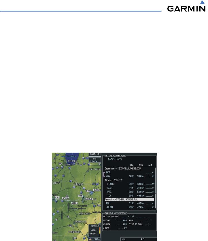
Load the selected airway segment into the flight plan
When the pilot presses the ENT Key with the cursor over the LOAD prompt on the Airway Loading Page, the selected airway segment is loaded into the flight plan. The system returns to the Flight Plan Page with the cursor position placed on the line just after the exit waypoint of the airway segment.
Figure 5-76 Returning to the Flight Plan Page
5-82 |
Garmin G1000 Pilot’s Guide for Cessna Nav III |
190-00498-02 Rev.A |

GPS NAVIGATION
In the example, waypoints FRANC and COU were originally in the departure procedure. Because the airway was loaded after ANX, those waypoints were removed from the departure, but were then added back in because they were also on the selected airway (V12). Note that FRANC and COU would have been removed from the departure regardless of which airway was selected at ANX.
The rules for removing bypassed waypoints in the original flight plan are as follows:
1.Waypoints within an arrival or approach procedure will never be removed during the load airway operation. Note that the pilot can always remove individual waypoints if necessary.
2.If there is a sequence of waypoints in the original flight plan starting with the entry waypoint that lines up with a sequence of waypoints in the new airway segment, that sequence is removed from the original flight plan (so it doesn’t get duplicated). This rule applies only to the departure and enroute/airway parts of the flight plan (not the arrival or the approach).
3.If the airway was inserted at a departure waypoint, all the waypoints in the departure procedure following the insertion point will be removed (when the pilot joins an airway from a departure waypoint, he is not intending to come back to the departure).
4.If the airway was inserted at an existing airway waypoint, the remaining waypoints in the airway will be removed (the pilot is using the Airway Loading page to replace all or part of the previously selected airway segment).
If there is not enough room in the flight plan to insert the airway segment, a pop-up message is displayed: “Flight Plan is full. Remove unnecessary waypoints.” When this happens, the flight plan will not be changed. Determination of “flight plan full” will account for the number of waypoints to be added with the new airway segment as well as the number of bypassed waypoints that would be removed from the original flight plan.
190-00498-02 Rev.A |
Garmin G1000 Pilot’s Guide for Cessna Nav III |
5-83 |