


4
Object Diagram
This chapter describes a technique to statically characterize the behavior of an object oriented system by means of diagrams which represent the class instances (objects) and their mutual relationships.
Although the class diagram is the basic view for program understanding of Object Oriented systems, it is not very informative of the behavior that a program will exhibit at run time, being focused on the static relationships among classes. On the contrary, the object diagram represents the instances of the classes and the related inter-object relationships. This program representation provides additional information with respect to the class diagram on the way classes are actually used. In fact, while the class diagram shows all possible relationships for all possible class instances, the object diagram takes into consideration the specific object allocations occurring in a program, and for each class instance it provides the specific relationships a given object has with other objects. While in the class diagram a single entity represents a class and summarizes the properties of all of its instances, in the object diagram different instances are represented as distinct diagram nodes, with their own properties. Thus, the dynamic layout of objects and inter-object relationships emerges from the object diagram, while it is only implicit in the class diagram.
A static analysis of the source code based on the flow propagation in the OFG can be exploited to reverse engineer information about the objects allocated in a program and the inter-object relationships mediated by the object attributes. The allocation points in the code are used to approximate the set of objects created by a program, while the OFG is used to determine the inter-object relationships. Resulting diagrams approximate statically any run-time object creation and inter-object relationship, in a conservative way.
A second, dynamic technique that can be considered to produce the object diagram is based on the execution of the program on a set of test cases. Each test case is associated with an object diagram depicting the objects and the relationships that are instantiated when the test case is run. The diagram can
64 4 Object Diagram
be obtained as a postprocessing of the program traces generated during each execution.
The static and the dynamic techniques are complementary, in that the first is safe with respect to the objects and relationships it represents, but it cannot provide precise information on the actual multiplicity of the allocated objects (e.g., in presence of loops), nor on the actual layout of the relationships associated with the allocated objects (e.g., in presence of infeasible paths). The dynamic view is accurate with concern to the number of instances and the relationship layout, but it is (by definition) partial, in that it holds for a single test run. Therefore, it is useful to contrast the dynamic and static view, to determine the portion of the latter that was explored with the available test suite and to refine it with information suggested by the dynamic views.
This chapter is organized as follows: after a summary presentation of the object diagram elements, given in Section 4.1, Section 4.2 describes a static method for object diagram recovery. It is a specialization of the general purpose framework defined in Chapter 2. Section 4.3 provides the details of an object sensitive OFG algorithm for the recovery of the object diagram. The dynamic technique for object diagram recovery is presented in Section 4.4. At the end of this section, static and dynamic analysis views are contrasted, highlighting advantages and disadvantages of both, and providing hints on how they can complement each other. Static and dynamic extraction of the object diagram is conducted on the eLib program in Section 4.5. Related works are discussed in Section 4.6.
4.1 The Object Diagram
The object diagram represents the set of objects created by a given program and the relationships holding among them. The elements in this diagram (objects and relationships) are instances of the elements (classes and associations, resp.) in the class diagram. The difference between an object diagram and a class diagram is that the former instantiates the latter. As a consequence, the objects in the object diagram represent specific cases of the related classes. Their attributes are expected to have well defined values and their relationships with other objects have a known multiplicity. For each class in the class diagram there may be several objects instantiating it in the object diagram. For each relationship between classes in the class diagram there may be object pairs instantiating it and pairs not related by it.
The usefulness of the object diagram as an abstract program representation lies in the information specific to the instantiation of the classes that it shows. While the class diagram summarizes all properties that objects of a given class may have, the object diagram provides more details on the properties that specific instances of each class possess. Different instances may play different roles and may be involved in different relationships with other
4.2 Object Diagram Recovery |
65 |
objects. While this is not apparent in the class diagram, the object diagram represents this kind of information explicitly.
Let us consider a hypothetical BinaryTree program. In its class diagram, there might be one BinaryTreeNode class, with two auto-associations named left and right for the two children, while a possible instance represented in the object diagram might include three objects of type BinaryTreeNode, playing three different roles (i.e., tree root, left child and right child). The relationships among these three elements are compliant with those in the class diagram, but provide more information on the layout of the related instances by showing a specific scenario (where the root references two children which have no further descendants). Moreover, the object diagram is the starting point for the construction of the interaction (collaboration and sequence) diagrams, where information about the message exchange between objects is added to the class instances, thus focusing the view on the dynamic behavior of a set of cooperating objects (a collaboration, in the UML terminology).
In the following text, two techniques are described for the recovery of the object diagram. The first exploits only static information and approximates the set of objects created in the program by analyzing the allocation (new) statements and propagating the resulting objects by means of the flow propagation algorithm described in Chapter 2. The second considers a set of execution traces, associated with the test cases available for a given program, and obtained by running an instrumented version of the given program. Execution traces include information about each object allocated by the program, uniquely identified, and its attributes. Object attributes which reference other objects are used to recover inter-object associations. These two techniques have advantages and disadvantages, and it is therefore desirable to be able to compute and integrate the results of both of them.
4.2 Object Diagram Recovery
The static computation of the object diagram exploits the flow propagation on the OFG to transmit information about the objects that are created in the program up to the attributes that reference them. Objects are identified by allocation site (i.e., the line of code containing the allocation statement), with no regard to the actual number of times it is executed (which is, in general, undecidable for a static analysis).
Fig. 4.1 shows the flow information that is propagated in the OFG to recover the object diagram. Each allocation site (statement of kind (5)) is associated with a unique object identifier, constructed as the class name  subscripted by an incremented integer
  (giving the object identifier
  Such flow information is propagated in the OFG according to the algorithm given in Chapter 2, in the forward direction.
Construction of the object diagram is a straightforward post-processing of the computation described above. Every object identifier  generates a
66 4 Object Diagram
Fig. 4.1. Flow propagation specialization to determine the set of objects allocated in the program that are referenced by each program location.
corresponding node in the object diagram. Every node in the OFG associated to an object attribute, i.e., having a prefix  and a suffix
  where
where  is an attribute of class
  is taken into consideration when inter-object associations are generated. The out set of such an OFG node (i.e., out[c.a]) gives the set of objects reachable from all objects
  of class
  along the association implemented through the attribute
  Such an association can thus be given the name of the attribute,
binary search tree example
4.2 Object Diagram Recovery |
67 |
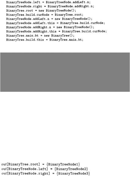
The abstract syntax representation of the Java code fragment above is the following:
Fig. 4.2. Object flow graph for the binary tree example.
Fig. 4.2 shows the OFG derived from the abstract statements above. Non empty gen sets of OFG nodes are also shown. Objects of type BinaryTreeNode are allocated at three distinct program points, thus originating three object identifiers, BinaryTreeNode1, BinaryTreeNode2 and BinaryTreeNode3, which are in the gen set of the respective left hand side locations (BinaryTree-
.root, BinaryTreeNode.addLeft.n and BinaryTreeNode.addRight.n). Since there is just one allocation statement for BinaryTree objects, the only object identifier for this class is BinaryTree1, inserted into the gen set of the allocation left hand side, BinaryTree.main.bt.
After flow propagation, the following out sets are determined for the class attributes:
Construction of the object diagram is now possible. Every object identifier becomes a node in the object diagram. Thus, in the example above four nodes are inserted into the diagram, three of class BinaryTreeNode and one of