


5.2 Interaction Diagram Recovery |
95 |
Fig. 5.4. Sequence (top) and collaboration (bottom) diagram built after call resolution for method addLoan in class Library.
5.2.1 Incomplete Systems
In order to produce complete interaction diagrams, the algorithm described in the previous section requires that all allocation points are in the code under analysis. This means that the system under analysis comprises all the driver modules necessary to build all of the needed objects. However, in Object Oriented programming it is very common to build only an incomplete system, consisting of a cohesive set of interacting classes that perform a given, well defined task, and are expected to be reused in different contexts. In these cases it would be desirable to be able to derive the interaction diagrams even if not all object creations are in the code, to understand the behavior of the incomplete subsystem in isolation, independently of its usages in a given application. To achieve this, all method invocations are taken into consideration and when the source or the target of a call are not associated with any recovered object, although their classes are part of the system under analysis, a generic object is introduced. The result is an interaction diagram in which placeholders (marked with an asterisk) for generic objects are present for objects not allocated inside the analyzed code.
Resolution of method calls for incomplete systems is shown in Fig. 5.5. All calls in the program are considered in sequence Results of flow analysis are
96 5 Interaction Diagrams
Fig. 5.5. Resolution of all method calls for incomplete systems.
used to determine the source and target objects (invocation of procedure resolveCall). If one or both of the two sets are empty, a generic object associated to the declared class or interface is used instead  indicates a generic object of class/interface A or any derived/implementing class). In this way call edges are generated even when the object analysis algorithm fails to determine the object issuing or receiving a message.
When an object  allocated in the program portion under analysis is the source or target of a call, it cannot be excluded that another externally allocated object be an alternative source or target of the same call. Thus,
  must be always assumed implicitly as an alternative source or target, unless further information is available about the excluded code. Moreover, if the excluded code introduces data flows that alter the OFG, it is necessary to take them into account, in order for the result to remain conservative. An example of this situation is the presence of external container classes, discussed in
detail in Chapter 2. The presence of a label |
indicates that no allocation |
|
point for the given object was found in the code, while |
indicates that at |
|
least one allocation point was found, although other external allocations may also exist.
When, in the presence of subclassing, the allocation point is part of the analyzed code, the allocated object is assigned the exact type (e.g., if A1 inherits from A and the allocation expression is new A1() the object will be identified accurately as  On the contrary, when a generic object is introduced because the allocation point is missing, the actual type may be any derived class, and the recovered information is less precise than for objects allocated
in |
the code |
is used for the external allocation of objects of any subclass |
of |
A, including |
A itself). |

5.2 Interaction Diagram Recovery |
97 |
eLib example
Let us consider the code of just the core classes of the eLib program (Appendix A), excluding the driver class Main reported in Appendix B. When method addLoan (line 40) from class Library is analyzed, the source object of the four calls it contains (lines 42, 43, 45, 46) is not known. Actually, no allocation of objects belonging to class Library is performed inside the code in Appendix A. While for the first two calls it is possible to determine the target object, which is Loan1, the Loan object allocated at line 60, this is not possible for the last two calls. No object of either classes User and Document is ever allocated in the code under analysis. Correspondingly, the set targets returned by the procedure resolveCall is empty for the calls at lines 45, 46.
Fig. 5.6. Sequence (top) and collaboration (bottom) diagram for method addLoan in class Library. The analyzed code excludes the driver class Main.
Application of the rules in Fig. 5.5 leads to the introduction of a generic object  as the source of all four calls. Moreover, the generic objects
  and
and  are introduced for the calls at lines 45, 46. The resulting sequence and collaboration diagrams are shown in Fig. 5.6. By contrasting them with those in Fig. 5.4, the approximations introduced by generic objects become apparent. Only superclasses (e.g., User and Document) of actually allocated classes are specified with the generic objects, and no reference to specific allocation statements can be given (e.g., in Fig. 5.4 User1 is the object allocated at line 382, while in Fig. 5.6 allocation of
  is external and unknown).
985 Interaction Diagrams
5.2.2Focusing
The interaction diagrams in Fig. 5.4 and 5.6 represent the message exchange among objects triggered by the execution of the method addLoan inside the class Library. In other words, the view focuses on the interactions occurring when a particular computation (i.e., method of interest, such as Library. addLoan) is performed. This corresponds to the natural approach of drawing the interaction diagrams in forward engineering. In fact, it usually makes no sense to draw just one huge diagram for the whole functioning of the system. It is preferable to split it up according to the most important subcomputations (i.e., the most important methods for the selected functionality). This is the key to handling the complexity of large systems.
When interaction diagrams are reverse engineered, the overall plot containing all objects and all message exchanges may be unusable, because its size may exceed the cognitive abilities of humans even for relatively small systems. However, it is possible to focus the view on specific methods, thus following the natural approach to the construction of these diagrams. This is achieved by restricting the view to a subset of the calls issued in the program: those belonging to a method of choice. The corresponding modification of the recovery algorithm is as follows. First, the procedure resolveAllCalls in Fig 5.5, which returns all call edges in the whole interaction diagram, is run. Then, only the nodes reachable in the call graph (the graph representing the call relationship between pairs of methods) from a method of choice are taken into account. The set of call edges returned by procedure resolveAllCalls is thus restricted to the methods in a selected portion of the call graph.
If this is not enough to produce interaction diagrams of manageable size, the second option available to the user is cutting a part of the system and analyzing an incomplete system, in such a way that it still includes all the key classes involved in the computation of interest. As discussed in the previous section, the introduction of generic objects allows analyzing incomplete systems as well. To summarize, applicability of the proposed approach to large systems can be achieved by filtering the relevant information in two ways:
1.Only the calls issued directly or indirectly from a method of interest are resolved.
2.An incomplete system, including only the interesting classes, is analyzed.
Method calls in a focused collaboration diagram are numbered according to the Dewey notation. Such numbering is exploited also to draw the sequence diagrams, in that the temporal (vertical) ordering is induced by them. It is possible to obtain the proper numbering of method calls by means of the numbering algorithms shown in Fig. 5.7, 5.8.
The first step, described in Fig. 5.7, consists of numbering each call statement in the program. The first time the procedure numberCalls is invoked, it has a method body (block of statements) as first and 1 as the second parameter. An incremental number is associated to each call statement (line 3)
5.2 Interaction Diagram Recovery |
99 |
Fig. 5.7. Numbering of method calls.
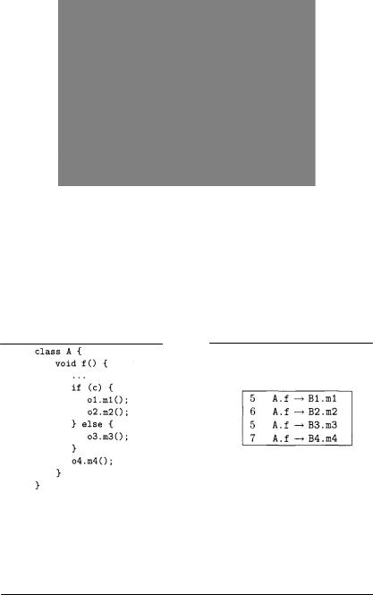
and each nested block of statements is handled similarly to the main block, by recurring inside it (at line 11 only the case of a while loop containing a nested block is represented for simplicity). Statements with more than one nested block of statements, such as an if statement with both then and else part, require a special treatment, in that the value of the number to use for the first statement following the if must be the maximum between the values generated inside the two nested blocks of statements (then and else part of the if).
example
Assuming num equal to 5 when the if statement above (inside method f of class A) is encountered, the absolute numbers attached to the calls to B1 .m1 and B2.m2 are respectively 5 and 6, the absolute number attached to B3.m3 is 5, and the next value of num, used for B4.m4, is 7 (assuming that variables o1, o2, o3, o4 belong respectively to classes B1, B2, B3, B4). The alternative between the two branches of the if is indicated by giving them a same initial numbering (5, for both  and
and 

100 5 Interaction Diagrams
Fig. 5.8. Numbering of method calls focused on a method.
The second step in the generation of the Dewey numbers for the collaboration diagram, summarized in Fig. 5.8, is run under the assumption that the view is focused on some method. Correspondingly, numberFocusedCalls is invoked with the body of the selected method as the first parameter, and an empty Dewey number as the second parameter. When a call is encountered, the related Dewey number is obtained by concatenating the current Dewey number and the number of the call, separating them with a dot (line 3). The new Dewey number generated for the call is passed to a recursive invocation of numberFocusedCalls, executed on the body of the called method (line 7). Computation of the Dewey numbers inside the called method is not activated in case recursion is detected (check at line 5). For the other statements (lines 11 through 17), the procedure just enters each nested block of statements, where it is reapplied.
When multiple objects, belonging to different classes, are determined as the targets of a call (e.g., InternalUser1 and User1 for the call to addLoan in Fig. 5.4), the content of the invoked method may differ from object to object (method overriding). The procedure to compute the Dewey numbers (numberFocusedCalls in Fig. 5.8) is recursively called (line 7) for each different implementation (body) of the overridden method, thus including all of the possibile alternatives.
|
5.2 Interaction Diagram Recovery |
101 |
||
|
eLib example |
|
|
|
|
|
|
|
|
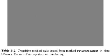
Let us consider the direct and indirect method calls issued from |
inside |
|||
the body of method returnDocument, class Library, line 66, shown in Table 5.2. The first called method, isOut, in turn invokes method isAvailable from class Document. Method getBorrower (second call in returnDocument) invokes getUser from class Loan. Finally, Library.removeLoan, the last invocation inside returnDocument, triggers the execution of four methods, reported at the bottom-right of Table 5.2. These do not perform any further method invocation.
Method calls are numbered in Table 5.2 (column Num) according to the rules given in Fig. 5.7. Let us consider a collaboration diagram focused on method Library.returnDocument. Computation of the Dewey numbers (see Fig. 5.8) starts with the body of method Library.returnDocument and an empty Dewey value. The three calls issued inside this method are thus numbered 1, 2, 3. Procedure numberFocusedCalls is then reapplied to the body of Document.isOut, with a current Dewey value equal to 1. The call to isAvailable issued inside Document.isOut is correspondingly numbered 1.1. Similarly, the call to Loan.getUser inside Document.getBorrower is numbered 2.1. Another call to the same method, issued from method Library.removeLoan, receives a different Dewey number: 3.1. The final Dewey numbers produced for the collaboration diagram focused on returnDocument are displayed in Fig. 5.9.